|
|
Post by mlrpa on Aug 7, 2014 17:42:54 GMT -5
hey all, long time, no see.
I recently picked up, dirt cheap I might add, a Gibson L6-S. I am in the process of rebuilding it back to the original wiring. ie: the 6 way switch, the mid control, et al. Here are my issues.
1) I don't speak schematic. you talk about micro henries, I give you the lost deer in the headlights look. I found the wiring diagram for the L6S, and I can make sense of it, but knowing the difference of a uH and a mH, I haven't a clue. Can someone PLEASE send me a link where I can buy just exactly what I need?
2) is the diagram that was posted, saying it was a 3.0 Henrie inductor, correct? Again, I haven't a clue.
Thank you so much for the help.
|
|
|
|
Post by newey on Aug 7, 2014 22:38:11 GMT -5
Everything we ever said about the L6-S is here: guitarnuts2.proboards.com/thread/1449In that thread, someone mentioned the inductor to be .9H, ChrisK noted that he used a 1H in his test mule and it was too large a value. Someone else said Bill Lawrence recalled it at 1.4H. No one said anything close to 3H, not sure where you got that value. A 3H inductor is also going to be a fairly sizable piece, I'm not sure you'd get one into the cavity. Also note that the wiring changed with later versions of the guitar. |
|
|
|
Post by b4nj0 on Aug 8, 2014 1:21:17 GMT -5
You could play around with some LT700 transistor audio output transformers. They're cheap enough and quite small. Just add them in series until you get to the value that works for you. I bought a 1.5 Henry inductor from a Dutch eBay trader and I'm convinced that it's just a couple of LT700s potted in opaque resin.
e&oe
|
|
|
|
Post by JohnH on Aug 8, 2014 2:00:36 GMT -5
Here's a place to buy such things: Q filtersThe main advantage of buying those ones is that they come with a specified value stated, since various salvaged inductors around the house will have unknown values, and most meters will not measure inductance (but mine will, and it was only $50 new!) The link describes filters for guitar at 1.8H and for bass at 3H, but I don't think that is a given. I can run an inductor in the GuitarFreak spreadsheet, so here are some comparisons of frequency response. They are based on a standard PAF-style humbucker with 500k pots, and the Q-filter in place of the tone cap. First, here is a base case, where blue is the tone knob at max for minimal effect, then red with tone knob down to 2 to see the effect of a 1.8H Q-filter / inductor:  In this next one, same knob position at 2, and blue is now the 3H, and red is the 1.8H  I haven't tried any of this IRL, but the 3H seems more appealing to me. They seem to act like as you turn down, it cuts mids and raises the peak frequency, transitioning to a nearer to single-coil sound as inductances of filter and pickup combine. |
|
|
|
Post by mlrpa on Aug 8, 2014 15:49:41 GMT -5
Well, thanks all for the quick replies, but truly, it's a Klingon version of Greek to me. I see mention of uH, nH on sites selling inductor coils, and still I can't figure out how it relates to .9H? As to answer where I got the 3 H mark, it came from here: guitarnuts2.proboards.com/thread/5569/passive-eq-circuit?page=3I just bought a Q-filter, and hopefully, I can make it work as the original wiring did in the L6S, and Bill Lawrence intended. It's funny. I can rewire a guitar in minutes, series, parallel, coil tapping, whatever, not a problem. but this is so beyond me, I feel like this is the first time I have ever picked up a soldering iron! |
|
|
|
Post by b4nj0 on Aug 8, 2014 17:17:21 GMT -5
milli>micro>nano>pico>etc...
These are each 1/1000 the value of the next.
So 0.9H is 900 milliHenries and so 900,000 microHenries and thus 900,000,000 nanoHenries and so on and so on.
IIRC. If not then I must apologise and fall on my sword!
e&oe
|
|
|
|
Post by JohnH on Aug 8, 2014 18:42:45 GMT -5
Well, thanks all for the quick replies, but truly, it's a Klingon version of Greek to me. Oh, OK sorry about that. I used an online translator to convert my last post into Klingon: filters HurDagh DeSDu' 1.8 h 'ej 3 h DeSDu' bass Del link 'ach Qo' 'e' vIHar 'e' nob. inductor laH qet jIH qaStaHvIS guitarfreak spreadsheet, vaj naDev Se' response comparisons 'op. waw' chaH Hol paf-style humbucker 'un k 500 je q-filter in place of 'uybogh pegh yuvtlhe'. wa'DIch, naDev waw' case, nuqDaq SuD 'uybogh pegh knob DeSDu' max minimal 'angbogh Da, vaj Doq 'uybogh pegh knob down to 2 'angbogh Da 1.8 h q-filter vIlegh ghap inductor:So hopefully that is all clear now. |
|
|
|
Post by sumgai on Aug 9, 2014 11:00:13 GMT -5
It's funny. I can rewire a guitar in minutes, series, parallel, coil tapping, whatever, not a problem. That's because what you just described is nothing more than different kinds of logic problems, when you get right down to it. That's not beyond the reasoning powers of nearly all guitarists.  However, when it comes to electrical theory, we're no longer in simple logic territory, we're cruising into physics and the like. In fact, maybe more like dive bombing in that direction! So here's a nutshell version of what I used to take a whole quarter to teach to beginning students: At any given frequency, the three main passive components in a circuit are going to have an effect, like so: A capacitor will hinder voltage. For arcane reasons way beyond our needs here and now, I'll leap over a lot of theory and get to the point: as frequency rises, greater voltage passes through any given value of capacitor; A coil (or inductor) will hinder current. For the same reasons above, and in the interests of time, we'll take another Superman-sized bound over a tall building, and end up with: as frequency goes down, greather current passes through any given value of an inductor; and: A resistor will simply hinder both current and voltage, and do so by the same amount no matter what the frequency; Now these may not seem intuitive at first, because voltage and current go together, hand in hand... don't they? No, actually, they don't. But again for our needs, all the reasoning behind those actions are not germane to our conversation here and now. I'll cut to the chase and end up with this statement of The Bottom Line (as needed by guitarists): More or less, a 0.1H inductor will have little to no effect on our tonal output, given the nominal 0.05µF (or smaller) value caps we tend to use. Yes, we can trim those values and get some effect, but overall..... I can go on and on, but then I'd be digressing, and we wouldn't want that, now would we? So for now, suffice it to say that you're doing things right, and that you don't need to go any further down the rabbit hole, unless you're feeling masochistic!  HTH sumgai |
|
|
|
Post by JohnH on Aug 9, 2014 16:27:48 GMT -5
I was also thinking some more about how to describe in words istead of in graphs, what to expect an inductor to do when wired into a guitar, in the same manner as a tone capacitor.
I think it acts in two ways. First, given that we are familiar with how a tone cap acts to cut highs, then the inductor is the opposite and it cuts mids and lows as you roll down. The other point is that, we are familiar with how putting pickup coils in parallel can make for a brighter sound combined, and that is what adding the inductor coil will do, with the difference that it is not itself adding to the signal but rather just changing electrical characteristics to shape the tone.
|
|
|
|
Post by mlrpa on Aug 11, 2014 16:02:53 GMT -5
Thank you Johm, and Sum, that makes sense to me now. Now, another question/dilemma/opportunity to earn beer for you guys. I have the aforementioned L6S. I love it, and want it back to original as much as possible. I found the wiring diagrams, and found a switch. 6 position, 24 pins, 4 pins as out, (I assume) The diagram doesn't help me much, though this one does, a bit. Still, I am a bit lost. Is there some way someone can write out an idiot diagram, showing the physical placement of the wires to the switch? Here is a pic of the switch I purchased: s184.photobucket.com/user/penguinguitars_photo/media/PICT0136.jpg.html?filters[user]=48137706&filters[recent]=1&sort=1&o=0s184.photobucket.com/user/penguinguitars_photo/media/PICT0139-1.jpg.html?filters[user]=48137706&filters[recent]=1&sort=1&o=1and the diagram I found: i528.photobucket.com/albums/dd324/williamsanders127/b086abba.jpg |
|
col
format tables
Posts: 468
Likes: 25
|
Post by col on Aug 11, 2014 16:28:08 GMT -5
mlrpa,
Try posting those first two links again - they both point direct to this very thread (not the images you mentioned).
|
|
|
|
Post by mlrpa on Aug 11, 2014 17:26:33 GMT -5
Ok, sorry about that. 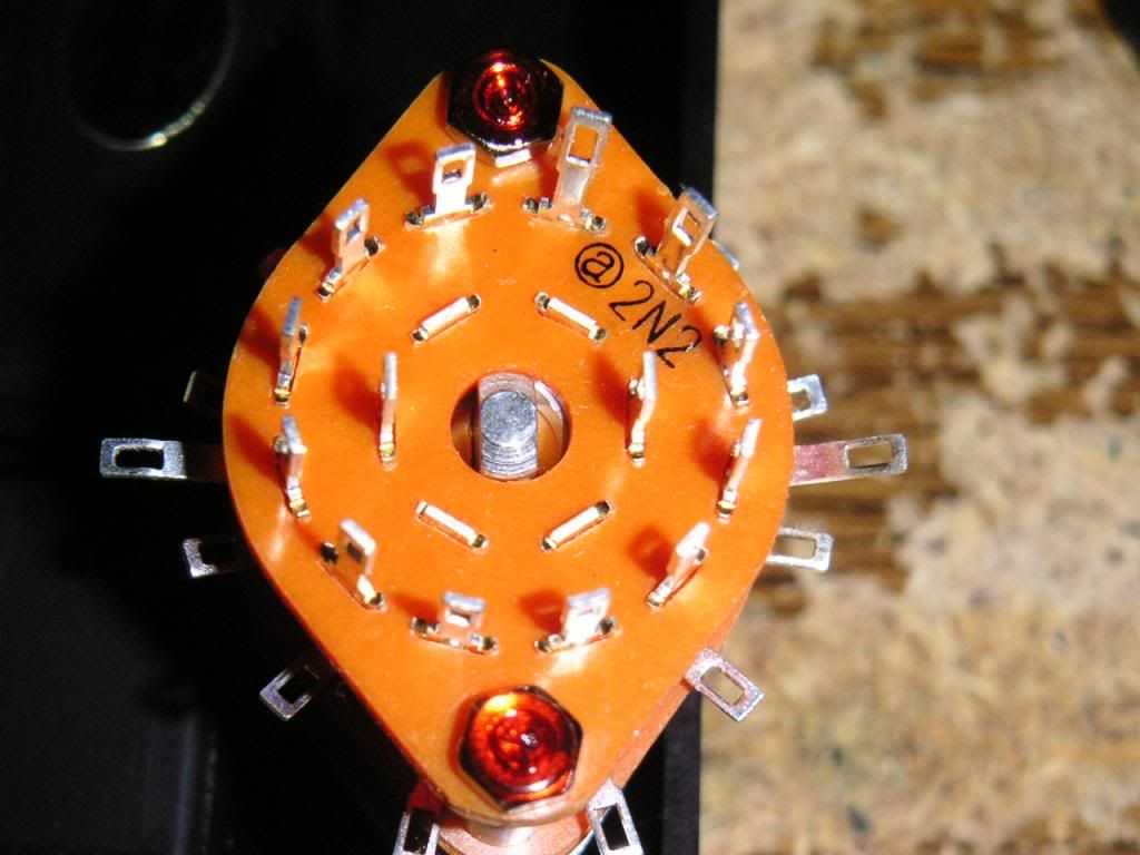 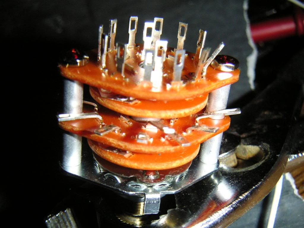 |
|
journeyman
Rookie Solder Flinger

Posts: 8
Likes: 0
|
Post by journeyman on Jan 13, 2015 6:54:51 GMT -5
John - It is most helpful to see a frequency graph as you have depicted it. I have a related question that I am hoping you could clarify with your insights. I had previously tried to use a Q-Filter (with the 1.8 H inductor) for a G&L ASAT Bluesboy Tribute (the humbucker was the stock G&L AS4255C alnico) and I used the wiring suggested on the Lawrence web site, for the option of the Q-Filter wired in series with an .020 cap and a 8K resistor wired in parallel; both pots were 250K nominal. My subsequent experience was that the tone was loud and muddy, and basically unusable, especially for the humbucker, unless the Q-filter pot was set down to just about 1. The single coil was a little more forgiving, but not by much, and the tone got very "harsh" as the tone dial went up, although not as "trebly" as I might have expected. Although I had followed the instructions and used the parts sent with the Q-Filter, it was clear that the standard recommendation was not going work well for this particular setup. That guitar has since been overhauled and no longer uses the Q-Filter. I am doing a new build now, hoping this time to incorporate the Q-Filter functionality more effectively in a different Telecaster. I am in the process of wiring a DPDT-switched tone pot to select either an .022 PIO cap or the Lawrence Q-Filter, fed by a "vintage" lower output neck humbucker in conjunction with a Duncan tapped Quarter-Pounder bridge, going through 500K volume and tone pots. (Similar to what the Lawrence site shows here: s1203.photobucket.com/user/wildepickups/media/Wiring%20Diagrams/QtoStandardTone.jpg.html?sort=6&o=9 ) Could you possibly suggest a better starting point for the parallel cap and resistor values that are in turn wired in series with the Q-Filter? And if I am totally off-base here, and you could recommend a better way to get the most variation in tone from using the Q-Filter, I would welcome any thoughts you might wish to share. Should I be using the 3.0 H inductor instead? I still think that a properly functioning Q-Filter could be a very useful addition to the sonic palette of the instrument - but I have not yet found a way to choose the correct value components to enable the Q-Filter to work as effectively as I hope it might. Any light you could shed on this situation would be VERY much appreciated. |
|
|
|
Post by JohnH on Jan 13, 2015 15:53:08 GMT -5
Hi journeyman and welcome to GN2
Thanks for your comments, and Im happy to help. Ideally, we can try to generate some plots pertaining to your specific set up. I use a spreadsheet for this, and you might be interested to see if you can run it yourself. It is in our Reference section, called 'GuitarFreak'
To use it, we need best-guess values of the electrical charactistics of your pickups. Resistance is easy to find or measure but inductance is much more important. Unless you have more specific info, would the humbucker be somewhat like a vintage PAF, at around say 7.5k and 4H? The quarter-pounder is less well known. I cant find an inductance for it. But it will be quite high and since it is described as being like a P90 then that may be the best assumption.
Ultimately youll need to experiment. The q-filter switching looks ok to me. Caps and resistors are cheap so getting a couple each of a half dozen values will be only a few $. The cap on that sketch is 0.01uF, and that is a fairly small value at least for when it is acting as a simpld tone cap.
Since you already have a 1.8H q filter, I suppose you will try that first.
|
|
|
|
Post by reTrEaD on Jan 14, 2015 13:42:26 GMT -5
Greetings, journeyman. You're in capable hands with John H. But I thought I should weigh in on part of your post: My subsequent experience was that the tone was loud and muddy, and basically unusable, especially for the humbucker, unless the Q-filter pot was set down to just about 1. If I understand correctly, when the tone control is turned to maximum, it's as if the Q-filter network is nearly disconnected from the circuit. So basically it's doing just about nothing, same as a capacitor would be doing in a normal tone-cut circuit with the pot at maximum. Thus I think the muddiness you experienced was a function of the HB itself (perhaps exacerbated by using lower resistance pots?). In my estimation the Q-filter network was doing something you found desirable but comparing the "unfiltered" tone to the more desirable sound lead you to believe something was amiss. |
|
journeyman
Rookie Solder Flinger
Posts: 8
Likes: 0
|
Post by journeyman on Jan 15, 2015 16:19:06 GMT -5
Thank you, reTrEaD - I had similar thoughts about the caps and especially the pot values - when I did the rebuild (without the Q-Filter), I first purchased about 6 500K CTS pots, which were all spec'd at a 10% tolerance; I found 1 at 370K, several in the 435-450 range, and 2 that matched exactly at 475K, which were the ones I used. Although that build had a different humbucker, and a completely different tone network, my guess is that the more appropriate value pots contributed significantly to the overall clarity of the new build. My uneducated opinion at this point is that if I were to reuse the original G&L AS4255C alnico humbucker with 500K pots that I would have similar improvements - I think the basic pickup is sound - it was, as you have pointed out, my choice of sticking with the stock 250K pots that likely were the determining factor in the muddiness I was hearing. Lesson learned!
For the new build with the P-90 neck and the tapped Quarter-Pounder bridge, I am going to follow up on John's suggestion and see what I can find from the plots of his spreadsheet, if I can determine the approximate inductance of these pickups. My ultimate goal is to have available some rather "strong" tones from these pickups in their native state, but to hopefully be able to also use the Q-Filter to "take a few windings off" sonically, and get a wider range of tones from those which might be otherwise available.
|
|
journeyman
Rookie Solder Flinger
Posts: 8
Likes: 0
|
Post by journeyman on Jan 15, 2015 16:49:46 GMT -5
Thanks, John -
I will try to find out from the pickup maker the inductance values that he is targeting for the specific "PAF"-like neck humbucker I have - it is described as a lower-output "vintage" wind, so the numbers you cited seem like they would be in the ballpark. The Duncan tapped Quarter Pounder bridge pickup inductance values should be hopefully known quantities. (As an aside - being able to input these numbers and producing an accurate frequency chart is a REALLY helpful way to quantify the effect all of these many variables!). My goal is to get pretty close tonally with a first estimate, and what I may do is to temporarily leave the RC / LCR components wired externally from the cavity, so I can empirically test, listen to the effect, and tweak with the actual strings and an amp in place - then "button it up" once I get to where I want to be. It's a Thinline variation, so the wiring is on the back of the pickguard, not as convenient as the traditional Tele cavity.
As I had mentioned to reTrEaD, I am using 500K pots for this build - my initial thought on the volume side of this wiring was to incorporate the "Kinman" treble-bleed mod; he recommends a .0012 mfd cap in series with a 130K resistor across the two non-ground volume pot lugs - but I always see this pictured with 250K pots; assuming that this affects the cutoff frequency - should I be thinking about adjusting these component values to keep the same rolloff characteristics when I use 500K pots?
- - -
One possible further consideration I had not mentioned - I had planned to do a 4-way wiring with the two pickups either series/parallel. That would provide 4 basic untapped pickup combinations, with 3 additional options using the bridge pickup in tapped mode. Having the Q-Filter in place to further 'trim the sails' should get me where I hope to be. I will keep you posted on my progress.
|
|
journeyman
Rookie Solder Flinger
Posts: 8
Likes: 0
|
Post by journeyman on Jan 15, 2015 17:03:49 GMT -5
Upon re-reading, apologies if I was unclear in the previous post - the PAF I had mentioned was in a build which I just completed; the build which I am currently working on has P90 in the neck position -
|
|
|
|
Post by JohnH on Jan 16, 2015 2:25:45 GMT -5
So really what you might want is your q-filter circuit to do something worthwhile with a wide range of pickup combination properties. Will consider further. For you treble bleed, if you want the most consistent tone, my conclusion was cap and resistor in parallel. 150k and 1nF to go with 500k pots, or a bit less cap if you want to turn right down below about 4. Some people like the Kinman series version, but the maths shows it not to be very consistent. heres a thread: Treble bleed |
|
journeyman
Rookie Solder Flinger
Posts: 8
Likes: 0
|
Post by journeyman on Jan 16, 2015 19:07:37 GMT -5
Great info on the link - I see why you are recommending that combination for the treble bleed - given that I am a very active user of volume and tone controls while playing, this looks ideal for those volumes between 5 and 10. VERY helpful - and I also see the shape differences in the response curves with the Kinman mod - may be good for some, but I just want to preserve the basic tonal characteristic independent of volume, and the parallel 150K with 1 nf looks like the ticket.
> So really what you might want is your q-filter circuit to do something worthwhile with a wide range of pickup combination properties.
This is EXACTLY what I am hoping to accomplish... "worthwhile" being a key (yet undoubtedly subjective) criterion. I find instruments that are tonally versatile in different sonic contexts most worthwhile. Thanks again, and I look forward to any suggestions you might be able to discern.
|
|
|
|
Post by JohnH on Jan 17, 2015 18:21:19 GMT -5
Here's some analysis of a modified tone control, which includes an inductor. The configuration is with a 500k pot in series with the inductor and a cap, with a resistor across the cap.
Varying the tone pot setting
This graph is based on a PAF style humbucker, a 1.8H inductor, a 22nF cap with a 33k resistor across it. The pot is 500k audio taper (10% at half way). The rest of the circuit includes a 500k volume pot and a 10' cable. The plots show settings of the tone knob from 10 to 0.
The blue line at 10 shows the natural peak at just over 3 kHz, based on the pickup inductance (3.8H in this case), and the capacitances, mainly due to the cable. In turning down, the first half of the turn seems to be all about reducing this peak, mainly by increased load due to the reducing pot resistance, and not really anything much to do with tone cap or inductor.
Below 5, a mid dip starts to happen, and also a new peak develops at a higher frequency. just below 6kHz. This higher frequency is due to the new inductance combining in parallel with the pickup inductance. The smaller either inductance is, the higher this new peak frequency will be. Note: these graphs assume linear frequency input and output, and only capture the electrical interactions. At 6kHz, its not clear how much real signal there will be coming out of the amp, from a real pickup.
The low end of the mid dip is determined by the inductances and the tone capacitor, and at very low tone stings, it is a sharp notch filter, in this case at about 850hz.
Different inductance values
This graph shows the difference with a 3H inductor (red), as compared to 1.8H (blue):
The pot is set at about 1, ie, just before a very deep notch occurs at 0. The larger inductor has greater impedance, keeping more of the body of the sound, and also, the new peak is not as high frequency, which might be better for electric guitar, even though this value is sold more for bass guitars.
Tone cap values
This shows the range varying the tone cap from 10nF(red) to 47nF(blue), with knob at 1. Previous plots were with 22nF.
The larger tone cap is lowering the frequency above which the circuit starts to cut. Very large caps (or no cap)will cut all the bass down to the general level. At 0 on the tone pot, the steep notch (see first plot)is defined by the tone cap and inductances, so larger caps will lower this notch frequency.
Resistor values
The value of the resistor across the cap sets how sharp the maximum notch will be. these plots are with tone pot at 0, with resistor varying from 22k (red), up to infinite (blue):

Conclusions
Tentatively, it seems that the main features of these varitone responses can be thought about and approximately evaluated independently. The new upper peak is due to the overall reduced inductance., the mid dip and notch is related to the inductance and tone cap.
I think a 3H may be a better value to have. Also, it may be good to use a 250k no load pot with this, to get a better spread of the main effects, and also a bit of extra treble.
Its also worth seeing this with just the inductor, no cap. Ill do this next.
|
|
|
|
Post by JohnH on Jan 18, 2015 0:38:07 GMT -5
Inductor only - no cap
This shows a smipler arrangement, just a 1.8H inductor in series with a 500k pot, with no tone cap. The pickup is a PAF Hb as before:

The upper frequencies show similar results to as in the previous post, but there is a more gradual decline in eth low mids. Plus, an interesting extra as you approach zero on the tine pot, a bass cut effect is provided. This would depend on the resistance of the inductor, which is not included here, so it may not be a real effect. Do you have a resistance value for the 1.8H inductor?
|
|
journeyman
Rookie Solder Flinger
Posts: 8
Likes: 0
|
Post by journeyman on Jan 18, 2015 5:31:05 GMT -5
John -
(I had a reply almost completed, tried to retrieve an additional image, and apparently lost it - (Doh!) - hopefully this is not a duplicate.)
A *very* interesting set of plots - particularly the first one ("Varying the tone pot setting") - if I am interpreting the effect on the previous build that I had described, this seems to correspond very strongly to what my perceptions were - the overall humbucker tone had been very dark, due to the stock 250K pots, and with the Q-Filter around "1", the cut in the mids (~700-3K) and the slight rise to a ~6K resonant peak seems to resemble very closely what I had perceived. At a setting of "0", the tone was too attenuated to really give me much to work with. The more I stare at this plot, it clarifies what I thought I heard - the tonal range was not especially useful to me, particularly with the 250K pots, but this now makes sense. It was definitely not a gradual coloring that progressed smoothly from 0-10.
As to the current build, where I am again trying to use the Q-Filter - this time more effectively, I followed your suggestion to try to find the inductance values of the two pickups from the manufacturer.
For the P90 style neck pickup, I received this reply (emphasis mine):
For the Duncan Quarter Pounder Tele bridge (tapped) I have not received anything specific back, but I *did* find this data from a previous correspondence. The untapped, full-on DC resistance seemed quite high to me (17.38K?) - I can measure this to double check in the morning, and I will check the tapped value as well, along with the resistance of the Q-Filter inductor.
These plots are really quite illuminating - this is very helpful.
|
|
journeyman
Rookie Solder Flinger
Posts: 8
Likes: 0
|
Post by journeyman on Jan 18, 2015 5:34:11 GMT -5
The last plot ("Inductor only - no cap") looks very promising - especially now that I am using the correct pots.
|
|
journeyman
Rookie Solder Flinger
Posts: 8
Likes: 0
|
Post by journeyman on Jan 19, 2015 4:41:13 GMT -5
I found some additional historical info on the Lawrence Q-Filter, courtesy of an older post (September, 2011) on freestompboxes.org by member gilmour_pugliese: N.B. - the value mentioned in the above reference is not the 1.8H nominal value of the Q-Filter that is sold today, but rather half of that value, 900 mH. There are some wiring diagrams included at the site as well, which mention some suggested resistor and capacitor values - the post I am citing is the 5th from the beginning at the link above. As to the previous question on the resistance value of the inductor (the Lawrence 1.8 H Q-Filter) - I measured it at 40 ohms. (does this seem correct?) Also, the DC resistance for the Duncan Quarter Pounder tapped Tele bridge pickup measured 8.7K ohms at the tapped lead. |
|
|
|
Post by JohnH on Jan 19, 2015 14:18:53 GMT -5
That's all good info. I'd say at this point, there is not much more to be learned before wiring it up with a couple of leads coming out of the guitar, so you can try some values. A handful of caps and resistors with a 500k pot and the inductor you already have should provide a pleasant evenings entertainment.
|
|


