|
|
Post by JeanFrancois on Apr 5, 2016 15:29:36 GMT -5
Hi! I want to switch the pickups of my Godin Session for a set of 3 Lollar Special S series. I have only been playing guitar for 3 years and I want to get as many sounds as possible out of the new wiring in order to better my ear and taste with a rich palette of sounds. By splicing wiring ideas from Deaf Eddie’s page, my guitar’s original wiring and stuff I read in various books, I (partially) came up with a wiring scheme that would enable me to switch between parallel and series configuration, shift the phase of the middle pickup, and switch between different capacitor values or bypass completely the tone and volume pots. I was wondering if you guys and girls could take a look at my diagram and give me your opinions, spot any mistakes I might have missed and answer a few questions: - Will the wiring behave in the intended way? - When the switch are set to “normal” mode (parallel wiring with RWRP middle pickup and a normal value capacitor for the master tone pot) will the guitar sound as if it was only wired this way or will the rest of the shebang still colour the sound even though it is bypassed? -For the caps, I was thinking 0.015, 0.022, 0.047 and 0.1; would I gain much to be a bit more adventurous with higher values?  ![]() 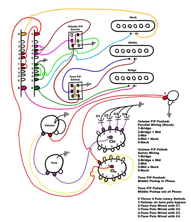 Thanks and please be gentle; this is my first post on this forum  Edit: I added the two shortcuts you recommended by newey to the phase switch. Changed the order of the 5 way switch positions in the legend so that they correspond with the actual diagram. I identified more clearly which switch positions corresponded to pickups linked in series. |
|
|
|
Post by newey on Apr 5, 2016 21:23:32 GMT -5
JeanFrancois- Hello and Welcome to G-Nutz2!OK, I'll put this as gently as I can. Your diagram is a good first effort. We like folks who show up with diagrams. But the diagram won't work as intended, for several reasons, so it's back to the drawing board. As for the good parts, your V and T controls, with the cap switching and the bypass of the controls, are all OK. The mid pickup phase switch is also OK, although you don't need to show both the upper right and lower left lugs as being grounded separately, you can just run a diagonal wire from lower left to upper right and then run to a single ground from there. You can also run diagonally from the "+" side, from lower right to upper left, thus avoiding 2 separate wires to the series/parallel switch. But your pickup switching is seriously amiss. First, we need to better define what you want. Your description says you will have regular Strat parallel combinations in one position of the Vol P/P switch, and then apparently some series combinations with the switch pulled. But I don't know what series combinations you intend to have, since your table of combinations reads the same for both series and parallel. (As a matter of our convention here, we use a "+" symbol for parallel, and "x" for series. You may wish to use a different designation, but either way, we need to know what series combos you intend.) If, however, your intention was that the series/parallel switch would put the middle pickup in series with the bridge at position 4 and in series with the neck at position 2, then the switch won't work as intended. It doesn't put the middle in series with anything. It also causes the ground leads for the neck and bridge pickups, at positions 2 and 4, to be wired to output via pole C of the 5-way switch. Since the hot leads of those pickups are also attached to output via C at positions 2 and 4, the pickups will be short-circuited to themselves at those positions, and you won't get any output from those pickups at positions 2 and 4. So, with the series/parallel switch pulled (and, using your chart's numbering, with neck as position 1), you will have: 1) N 2) M 3) M 4) M 5) B Not what you intended at all.  Also, your table shows the neck as being position 1 with the bridge as position 5. But the numbering seems to be reversed according to the numbering on the 5-way switch, where the neck "+" is connected to lugs 4 and 5. (It will also be helpful in discussing things if you number the switches when you redo the diagram. Call them "SW1", "SW2", etc. It's easier than writing out "Volume pot P/P"). As far as cap values, that's largely a matter of personal preference. You can easily experiment with different values by using a "cap substitution box" external to the guitar for testing different values. No problem there, there isn't any additional loading of the circuit in "normal" mode. Any added resistance across the rotary switch or the other switching is so negligible as to be meaningless. |
|
|
|
Post by JeanFrancois on Apr 6, 2016 18:36:57 GMT -5
First of all, thanks for your answer, I greatly appreciate the opportunity to have this discussion. I added the two shortcuts you recommended to the phase switch, changed the order of the 5 way switch's positions in the legend so that they correspond with the actual diagram and identified more clearly which switch's positions corresponded to pickups linked in series. I hope this help. As for the series/parallel switch, I cannot find where the mid pickup shorts out. Maybe their is something I am just not getting. The following version of my diagram highlights the path I think the current takes starting at the mid pickup all the way to the output. Hopefully with this, it will be easier to find the flaw in my thought process. The example I chose is position 4 with the Volume P/P pulled out (Mid x Neck).  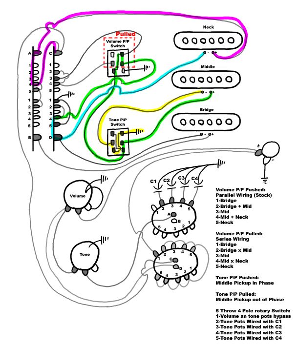 Neon Yellow: The ground lead of the Mid pickup is connected to the ground through the Tone P/P. Neon Green: The positive lead of the Mid Pickup passes the signal through the Tone P/P and then through the pulled Volume P/P. The signal then goes on to the D4 lug of the superswitch. Neon Blue: The signal passes from D4 to D which is connected to the neck pickup’s negative lead. Neon Pink: The positive lead of the neck pickup connects to A, the signal then passes to A4 which is connected to C, which is connected to the output through the other part of the diagram. I hope what I intended is a bit clearer. P.S. For the discussion's sake, let's call the Volume P/P SW1 and the Tone P/P SW2! |
|
|
|
Post by newey on Apr 6, 2016 22:15:04 GMT -5
OK, let me take a second look at this, I may have misinterpreted your diagram. Right now, after several glasses of chardonnay, I'll defer until tomorrow. |
|


