samushi
Rookie Solder Flinger

Posts: 3 
Likes: 0
|
Post by samushi on May 15, 2017 10:09:12 GMT -5
Hello everyone! I just joined the forum for it seemed like this would be the place where I'd get help. So, I've been building a stratocaster for almost eight years now (yes, eight years) and finally got it assembled only to find out that there's absolutely no signal when I plug it in. It has a schematic that I had to plan by myself for I couldn't find anything like it on the web. There's only one humbucker with two push-pull pots, and with the push-pull switches in different positions it is connected in series, parallel, single north coil and single south coil. I really hope someone has the time to go through the scheme below to check if there's anything wrong with it. I've checked it numerous times and it should work fine if I've understood everything right. If we get it working it could be useful for someone who has a single humbucker and two pots and wants to widen the tone range of the guitar without making any extra holes. 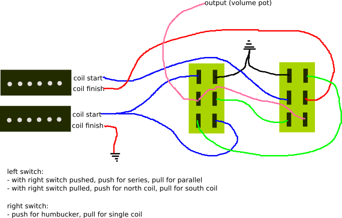 Edit: The upper coil is north and the lower coil is south, and the upper position of the switches is pulled and the lower is pushed. So, when the pickup is connected in single coil mode, one end of the excessive coil is connected to ground and the other end leads to nowhere. Should it work this way? Wouldn't there be a ground loop if both ends were connected to ground? I'm also wondering if the wires have been broken, I'm using single strand wire for I got it for free... Maybe shouldn't have. I'll have to check the circuitry with a tester when I get to it. |
|
|
|
Post by newey on May 16, 2017 5:48:12 GMT -5
Samushi- Hello and Welcome to G-Nutz2!You have come to the right place. What you're doing here is what our late member ChrisK called Binary Tree Switching. Scroll down through ChrisK's diagrams for the "DPDT Cell". I used this idea on my 4-coil "4caster". Yours is more simple, by 2 coils. The version that Chrisk outlines is somewhat different from yours, in that in his, both switches "down" gives series, both "up" gives parallel, and "one up, one down" gives the individual coils. That may be a little more intuitive in terms of the switching than what you have shown. Your diagram looks OK, although you haven't told us which coil is "N" and which is "S", and you haven't defined what "pushed" and "pulled" means in terms of your diagram. So, I can't say that your description follows the wiring, but the diagram will give you the 4 options. But, if you're getting no output whatsoever, regardless of switch positions, then your problem lies elsewhere. By all means, check wires for continuity if there is a question. That's fine. We often speculate that having a coil connected to the hot end and disconnected at ground (the so-called "hanging from hot" issue) could lead to excess noise under certain conditions. But if the hot is disconnected, no noise can enter the signal path. Shunting both ends of a coil to ground is also fine, and it doesn't create a ground loop, for the same reason- it's not in the signal path. In any event, it is unlikely that ground loops would be much of a problem, as we have also discussed over the years here. It may be a "best practice" to avoid them, but it's really not a concern in most cases. |
|
samushi
Rookie Solder Flinger
Posts: 3
Likes: 0
|
Post by samushi on May 17, 2017 4:17:40 GMT -5
Thank you so much for an inclusive answer! Such a relief to hear I don't have to change my plans but only find out the fault. Added the missing information, so the upper coil is north and the lower coil is south, and the upper position of the switches is pulled and the lower is pushed. I'll test the resistance of the connections in the next days and come back with what comes up!
|
|
samushi
Rookie Solder Flinger
Posts: 3
Likes: 0
|
Post by samushi on May 28, 2017 11:59:01 GMT -5
Alright, it's working! I found out that the pickup was wired out of phase. I think it still should have had some output? After I switched the coil other way around it still had no output with parallel and one south coil modes. I don't know what it was, because after a few days it just started working  I tried wiggling the wires if there was any bad connections that could have caused it but no. Ghosts and stuff. Thanks for the help, feel free to use the diagram now if you like! |
|
|
|
Post by thearbiter2001 on Sept 6, 2017 17:49:15 GMT -5
Does this still work as a volume and tone knob as well?
|
|
|
|
Post by newey on Sept 6, 2017 21:21:15 GMT -5
thearbiter
Hello and Welcome to G-Nutz2!
samushi's diagram doesn't show the pots, he stops short of them by just specifying the one output wire as going to the V pot. The rest of the pot wiring is understood to be as with any std. V and T controls. So, he's using push/pull pots, but has only shown the wiring to the switch portions, omitting the pots themselves.
|
|


 I tried wiggling the wires if there was any bad connections that could have caused it but no. Ghosts and stuff. Thanks for the help, feel free to use the diagram now if you like!