|
|
Post by reTrEaD on Jun 29, 2017 13:25:21 GMT -5
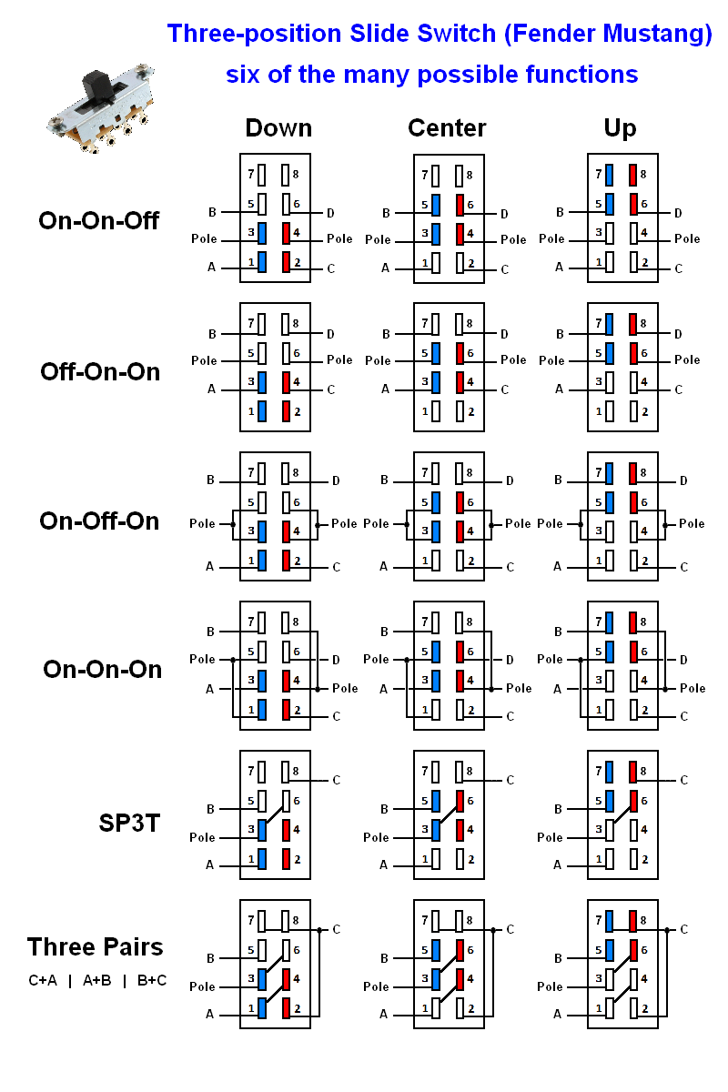
The Three-position Slide Switch used in the Fender Mustang is not well documented. The following exercise will help you begin to understand how it works. It isn't a DPDT on-off-on switch, although it can be wired to function that way. There is no lug that inherently acts as a common terminal per pole, in any position of the switch. Perhaps the most accurate, albeit clumsy, way to describe this switch would be: A three-position slide switch with adjacent-lug contact. If we orient the switch so that the slide moves in the vertical axis, we'll observe two columns of lugs. Each column is electrically isolated from the other. Referring to the attached drawing: In the DOWN position, lugs 1&3 are connected together, also lugs 2&4 are connected together. In the CENTER position, lugs 3&5 are connected together, also lugs 4&6 are connected together. In the UP position, lugs 5&7 are connected together, also lugs 6&8 are connected together. Although there isn't a defined 'pole', we can treat certain lugs as poles and evaluate the functionality and limitations of the switch in these circumstances. Further, with a few additional connections, we can alter the functionality. In the first example, the switch acts like a DPDT on-on-off switch. There is no such animal currently in a toggle version. Not likely to find much use for this, but who knows? The second example acts like a DPDT off-on-on. Again there is no equivalent in a toggle switch. We could treat the left half of the switch like the first example and the right half like the second example. left would be on-on-off, right would be off-on-on. That particular variation might prove to be useful. In the third example, a few additional connection are made which cause it to act in a similar fashion to a DPDT on-off-on toggle switch. We could certainly find a use for that. In fact, that's the way it's configured in the Fender Mustang. In the fourth example, connections are made to cause it to act in a similar fashion to a DPDT on-on-on toggle switch. We've found plenty of uses for the toggle version so this is likely to be useful. The fifth example functions as a SP3T switch. The sixth example is an interesting mutant I just conjured up. Similar to the fifth example except that in each switch position, a pair of lugs are connected to the pole. Maybe this will find a home somewhere. idk This isn't the end but rather just the beginning. There are plenty of other possibilities. But at least it's a start. I don't think people will be rushing out to buy these switches. The necessity of cutting a rectangular slot and drilling additional holes makes them an unattractive choice. But if you already have a guitar with one or two of these, you might have some interest in further exploration.  |
|
|
|
Post by sumgai on Jul 19, 2017 20:46:48 GMT -5
Nice contribution, reTrEaD, thanks. Stickied for future reference by all and sundry.
For the record....
A pole is defined by the cognoscenti as two or more terminals potentially sharing a connection by means of a conductor that can be moved so as to either permit or deny that connection. In no wise is a 'common' terminal defined as necessary for a pole to exist. In fact, using the word 'pole' is merely a convenience that describes more than one set of terminals controlled by a common operator (shaft, blade, toggle, etc.) that are never connected to each other by any internal means whatsoever.
sumgai
|
|
|
|
Post by Jaga on Mar 25, 2019 17:20:39 GMT -5
Sorry for bumping an old thread, but the topic is really interesting. Mustang switches can be pretty useful for the new builds.
There are nice mustang mods. Some ideas can be used in other applications.
|
|
|
|
Post by Jaga on Mar 25, 2019 18:03:24 GMT -5
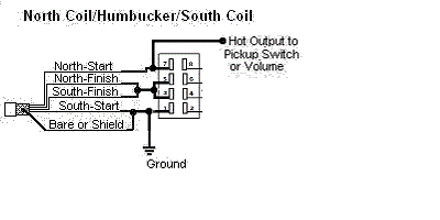
In a schematic Mustang switch could look like a combination of 2 DPDT switches and 1 DPST with a limited possibilities... Something like this (pink color is connected terminals): |
|
|
|
Post by Yogi B on Mar 27, 2019 6:51:41 GMT -5
I too recently rediscovered that site (via looking for info about the Yamaha DI-01). The specific Mustang page is here: Mustang Mod. (Damn HTML frames!) In a schematic Mustang switch could look like a combination of 2 DPDT switches and 1 DPST with a limited possibilities... I find the symbol used on the DBG Studio site pretty straightforward to intuit and is very close to the schematic symbols I've seen in switch datasheets. Make of that what you will, obviously being previously familiar with something aids understanding, but that I first found it in datasheets suggests that it is a good choice. If limiting oneself to representing a Mustang switch via DPDTs or DPSTs, I think it's easiest to comprehend a chain of three DPSTs in which only one is ever closed: |
|
|
|
Post by reTrEaD on Mar 28, 2019 13:26:30 GMT -5
Yogi B , I think the way DGB depicts the switch is perfect. 
|
|
|
|
Post by Jaga on Jun 27, 2019 18:46:04 GMT -5
I was thinking how to utilize Mustang switches and here what happened. Acutally it is pretty dirty since some combinations produce no sound. While I like the idea to modify series HB to parallel, I don't like that there is no logic in positions of sw1. I believe that it will lead to confusion during playing. Basically, sw1 works as expected only when sw2 is in the middle position, and only extreme positions are useful. Another drawback is that some combinations are silent, and there are only 4 electrically different sounds out of 9 positions.
Left switch in series mode (sw1 up):
1. North coil
2. Series 3. South coil Left switch in parallel mode (sw1 down): 1. North coil (south shorted)
2. Parallel 3. Parallel Left switch (sw1) in the middle position (the useless setting): 1. No sound, hanging coil (north)  2. No sound, hanging coil (north)  3. South coil Is it possible to improve this design?  |
|
|
|
Post by reTrEaD on Jun 28, 2019 10:14:17 GMT -5
hey Jaga , I don't think a Mustang switch fits well into your application. There aren't enough positions on one switch and too many if you use two switches. Two DPDTs (minitoggle, sub-minitoggle, slide, push-pull, whatever) can be wired to give you: Both in Series
North only
South only
Both in Parallel for the four possible switch positions. |
|
|
|
Post by Jaga on Jul 12, 2019 15:41:31 GMT -5
hey Jaga , I don't think a Mustang switch fits well into your application. There aren't enough positions on one switch and too many if you use two switches. That's true. I was thinking by contradiction: imagine, we have already wired pickups with 3-way switch to select 1 pickup, another pickup and both pickups in series. How would I add the switch to make them parallel?  |
|
omson
Rookie Solder Flinger

Posts: 2 
Likes: 0
|
Post by omson on Aug 23, 2019 7:45:11 GMT -5
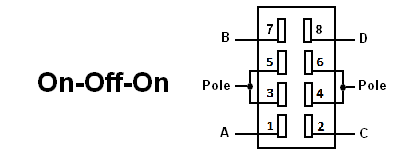
I'm wondering how to properly wire Mustang on-off-on switch for SPDT application like this diagram shows:
Can you help please?
|
|
|
|
Post by Jaga on Aug 23, 2019 7:57:54 GMT -5
I'm wondering how to properly wire Mustang on-off-on switch for SPDT application like this diagram shows:
Can you help please?
If you could look at the first post of this thread, one of the switches does exactly what you need: guitarnuts2.proboards.com/thread/8598/wiring-using-dpdt-mustang-switchesYou need the bottom left switch at the first post diagram (which does UP: NORTH; MID: SERIES; DOWN: SOUTH). The interesting thing is that one pole of the switch is not used and it can control two pickups simultaneously. |
|
|
|
Post by reTrEaD on Aug 23, 2019 14:21:48 GMT -5
I'm wondering how to properly wire Mustang on-off-on switch for SPDT application like this diagram shows: Can you help please?
Since you're starting with this:  The applicable section of the image in the OP would be the part marked On-Off-On, where the wiring of the switch is meant to act like a DPDT on-off-on switch.  We would only need one side of the Mustang switch to accomplish that same task.  |
|
omson
Rookie Solder Flinger

Posts: 2 
Likes: 0
|
Post by omson on Aug 23, 2019 16:59:47 GMT -5
I'm glad to see so qiuck response. Thank you guys very much!
|
|
|
|
Post by ravagetheearth on Sept 3, 2020 13:10:42 GMT -5
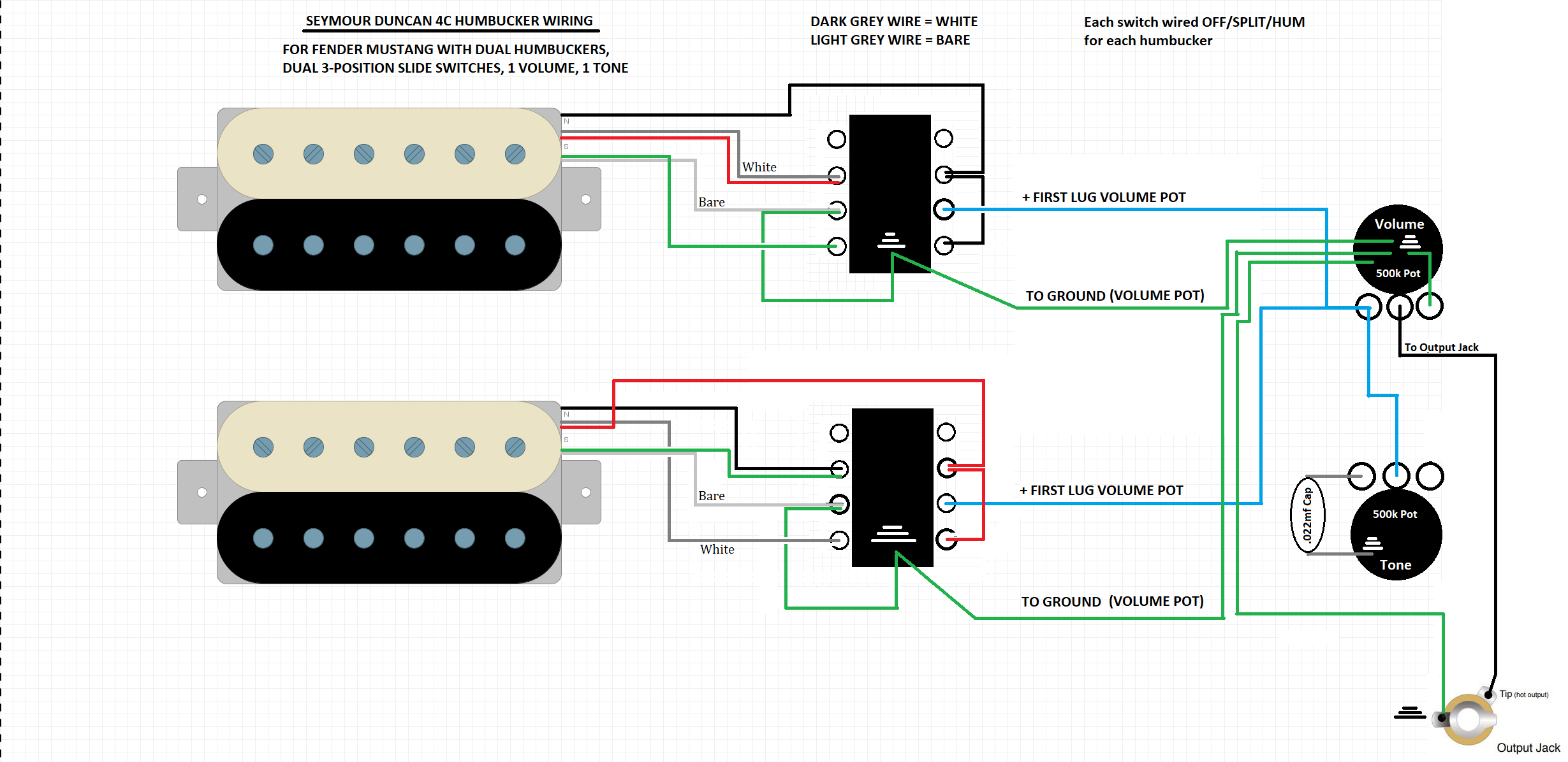
So I'm actually having some trouble with figuring this out. I'm worrying TWO humbuckers with each switch being OFF-SPLIT-HUM for their respective pickups. Here is what I've got so far. Not sure how correct it is, if at all.  |
|
|
|
Post by sumgai on Sept 3, 2020 22:33:58 GMT -5
rae, First,  to The NutzHouse!  Second, you're actually pretty close to the mark. Your only mistake that I can find is that the lower switch is not quite correct. See the upper switch? That's correct. Now I'm assuming that you wish the lower switch to work in the same order as the upper (in terms of which side is Off, etc.), and I'm assuming that you wish the coil splits to be hum-canceling when they're both on together. So... Look as the lower pickup's wires - the bare wire (and since it's tied to the green wire, that one also) goes to the switch's lower right terminal. But it's always grounded via the Vol pot's shell, yes? So when you hooked that wire to the lower right terminal, what do you suppose will happen when you engage that switch position? That's right, all signal will go to ground when in the Full Humbucker position. To remedy that, simply remove that pair of wires from that terminal. They'll still go to ground, just no longer to that terminal. Now duplicate the upper switch's right side onto the lower switch, and you're good to go!  HTH sumgai |
|
|
|
Post by reTrEaD on Sept 4, 2020 7:50:10 GMT -5
Hi ravagetheearth In addition to the problem sumgai noted regarding your lower switch, you're shunting coils when splitting. While this is never a deal-breaker, I prefer to avoid it when possible. I reworked your diagram slightly.  |
|
|
|
Post by sumgai on Sept 4, 2020 10:40:05 GMT -5
rae, Yes, reTrEaD's diagram is the better choice. I kept it simple, just change two wires. His setup requires more work, but there is a definite benefit. To keep the explanation short, a shunted (shorted) coil can contribute to some small-but-noticeable loss of "tone" (aka Mojo ®). We have at least a few threads around here that discuss that particular bugaboo, if you want/are-thirsty-for more details, but for now, just do it reTrEaD's way. Call it a "best practice".... we do!  HTH sumgai |
|
|
|
Post by Jaga on Nov 18, 2020 16:59:42 GMT -5
hey Jaga , I don't think a Mustang switch fits well into your application. There aren't enough positions on one switch and too many if you use two switches. Two DPDTs (minitoggle, sub-minitoggle, slide, push-pull, whatever) can be wired to give you: Both in Series
North only
South only
Both in Parallel for the four possible switch positions. Yes, you're right  I've redesigned a bit this idea to use 1 DPDT switch for “parallel overwrite” mode. Now there are 6 positions.  Left switch in series mode (sw1 up): 1. North coil 2. Series 3. South coil Left switch in parallel mode (sw1 down): 1. Parallel 2. Parallel 3. Parallel Could someone look into this and say if it is correct? It is based on the SingleA/Series/SignleB switching using ON-OFF-ON SPDT switch, and I tried to add the parallel mode. At the first glance this looks more complicated than 2 DPDT switches, but we could use second pole of the Mustang switch to control another set of pickups/coils. This might be useful to select only hum-cancelling combinations using single coils in HH/HSS/SSSS setup. |
|
|
|
Post by newey on Nov 18, 2020 17:27:20 GMT -5
Looks OK to me, jaga, with the understanding that the green line between lugs 2 and 3 on the Mustang switch is meant to show the internal switch connections for the slide, IOW, it is not a jumper wire between those lugs, correct?.
|
|
|
|
Post by Jaga on Nov 18, 2020 17:44:57 GMT -5
Actually, I was thinking that it was a jumper in order to simulate 1PDT ON-OFF-ON switch.
If it is not a jumper, how would it be possible to switch only the south coil?
|
|
|
|
Post by newey on Nov 18, 2020 18:56:47 GMT -5
In the center position (series), those lugs are connected internally, which means the "series junction" of the blue and red South coil wires are connected, giving you the series HB- no jumper needed.
With the S/P switch "up" to series setting, and the slide switch "down" to select the S coil, the slide switch connects the S coil red wire to output via lugs 3-4 of the slide. The S coil black wire is permanenetly grounded, so you hear the S coil. The N coil is also connected to ouptu, but the blue ground wire id disconnected, so you don't hear the N coil (although it is "hanging from hot", not a deal-breaker and probably unavoidable here).
But, if the green wire is in fact a jumper, with the S/P switch set to "parallel override",and with the slide switch set to "down", the S coil red wire shorts to the blue wire, which is grounded, so you will only get the N coil, not your "parallel override". You'll have "parallel/parallel/N coil instead.
Just remove the green jumper and all should be well, at least, as far as I see. We probably should get a second opinion.
|
|
|
|
Post by Jaga on Nov 18, 2020 19:12:15 GMT -5
But, if the green wire is in fact a jumper, with the S/P switch set to "parallel override",and with the slide switch set to "down", the S coil red wire shorts to the blue wire, which is grounded, so you will only get the N coil, not your "parallel override". You'll have "parallel/parallel/N coil instead.
Are you referring the left middle pin of the left switch? |
|
|
|
Post by Jaga on Nov 18, 2020 19:23:37 GMT -5
the S coil red wire shorts to the blue wire, which is grounded, so you will only get the N coil, not your "parallel override". You'll have "parallel/parallel/N coil instead. Looks like I got the idea. Do you mean that little blue wire between the switches?  I think that it is not grouned if both switches are in the down position, it's not connected to anything. |
|
|
|
Post by sumgai on Nov 18, 2020 21:03:58 GMT -5
Jaga, Pretend that the last few epistles didn't happen - your diagram in Reply #17 is correct, per your Truth Table. Get out that soldering iron and get crackin'!  HTH sumgai |
|
|
|
Post by newey on Nov 18, 2020 22:26:17 GMT -5
SOrry, Jaga, I missed that you were using an On-Off-On, I was assuming On-On-On
|
|
|
|
Post by sumgai on Nov 18, 2020 22:41:47 GMT -5
SOrry, Jaga, I missed that you were using an On-Off-On, I was assuming On-On-On reTrEaD said it best in his OP - giving the Mustang-style 3-position slide switch a proper nomeclature is a crap-shoot at best. My personal take is "on-on-on, no common", but most folks would still go "Huh?" to that, so I'm not much better, I admit. sumgai |
|
|
|
Post by Jaga on Nov 19, 2020 3:31:28 GMT -5
Thanks everyone for the feedback! This is supposed to be part of more complicated circuit (I like overcomplicating things  ). Will definitely share results. |
|
|
|
Post by reTrEaD on Nov 19, 2020 10:45:55 GMT -5
Could someone look into this and say if it is correct? It is based on the SingleA/Series/SignleB switching using ON-OFF-ON SPDT switch, and I tried to add the parallel mode. At the first glance this looks more complicated than 2 DPDT switches, but we could use second pole of the Mustang switch to control another set of pickups/coils. This might be useful to select only hum-cancelling combinations using single coils in HH/HSS/SSSS setup. , your wiring will work as-advertised but it will have unused coils shunted when only one pickup is selected. Also, the unused shunted Neck will be hanging from hot when the Bridge (only) is selected. None of this is a deal-breaker but should be avoided when possible. And it is possible in this case, although that would require using both sides of the Mustang switch. If that locks you out of your ultimate goal, I won't meddle. But if you'd like me to create a drawing on how to accomplish your current truth table more cleanly, I can spend some time on that tomorrow or the next. |
|
|
|
Post by sumgai on Nov 19, 2020 12:02:25 GMT -5
I like overcomplicating things  Well, that just got you promoted to the inner circle of Nutz-ism!   |
|
|
|
Post by Jaga on Nov 19, 2020 20:08:16 GMT -5
Jaga , your wiring will work as-advertised but it will have unused coils shunted when only one pickup is selected. Also, the unused shunted Neck will be hanging from hot when the Bridge (only) is selected. None of this is a deal-breaker but should be avoided when possible. And it is possible in this case, although that would require using both sides of the Mustang switch. If that locks you out of your ultimate goal, I won't meddle. But if you'd like me to create a drawing on how to accomplish your current truth table more cleanly, I can spend some time on that tomorrow or the next. Actually that's a difficult question what is the ultimate goal. I have a HSS (humbucker in the bridge) guitar and would like to wire it in some interesting way. Currently it has temporary wiring where all the pickups are in parallel having on-off switch (which is ridiculous). Of course, the binary tree concept can be applied to all 4 coils 3 times. Thus, all the options will be available. But I would like to limit them, because this way the amount of options would be crazy. I thought to use mustang switch to select N/M or humbucker coils simultaneously (either one of the coil or both). And later I could deal with 2 selected items somehow (actually I posted my ideas in the thread: guitarnuts2.proboards.com/post/89230). This might be cool, but there are two issues, one with the coils shunted. The other is that, probably, thus I won't have out-of-phase hum-cancelling combinations. It would be really cool to limit only to combinations that cancel hum + single coils, but not sure if it is possible. Probably that geocities article has answer, need to read it more carefully. I might use some rotary switch instead of tone pot if it helps. Generally I have to use several 2-way or 3-way slide switches since I have a Jaguar. I would be grateful for any ideas how to achieve that goal  |
|