spoom
Rookie Solder Flinger

Posts: 3 
Likes: 0
|
Post by spoom on Feb 12, 2018 12:40:29 GMT -5
So, this is my first attempt at making my own Wiring Diagram so i have probably missed something. Here's the idea: In Humbucker mode: 1 - Bridge Humbucker. 2 - Bridge Humbucker and Middle Singlecoil in series. 3 - Bridge and Neck Humbucker in parallel. 4 - Neck Humbucker and Middle Singlecoil in series. 5 - Neck Humbucker In Singlecoil mode: 1 - Bridge as Singlecoil. 2 - Bridge as Singlecoil and Middle Singlecoil in parallel. 3 - Middle Singlecoil. 4 - Neck as Singlecoil and Middle Singlecoil in parallel. 5 - Neck as Singlecoil. For this I'm using a 5-way super switch and a 4PDT switch. The black arrow on the diagram is the output and will go to volume and tone. As I said I've probably missed something and it probably doesn't work. So that's why I'm asking for help. (I'm using Seymour Duncans color codes) ![]()  I also have another question. I want to find a more useful replacement for my tone control since I basically never use it and found the Rothstein Guitars RG500D Passive Mid range Control. (http://www.guitar-mod.com/rg_passive.html) But I can't figure out how it works (and I'm not going to spend 60$ on one), they say that it removes mids in one direction and treble and bass in the other but i can't figure out how. So I'm thinking of building something similar and I'm probably going to install a bypass switch for it. How do they work? Are they any good? Any other good replacements for my tone control? Thanks in advance for any help/answers. Oh and sorry for the messy diagram. |
|
|
|
Post by reTrEaD on Feb 12, 2018 13:39:55 GMT -5
Hello spoom I'm a bit short on time right now so I'll leave your questions in the capable hands of others here. But I thought it might be helpful for them to have an image to work with which had some better contrast between the background and the switches and wires. 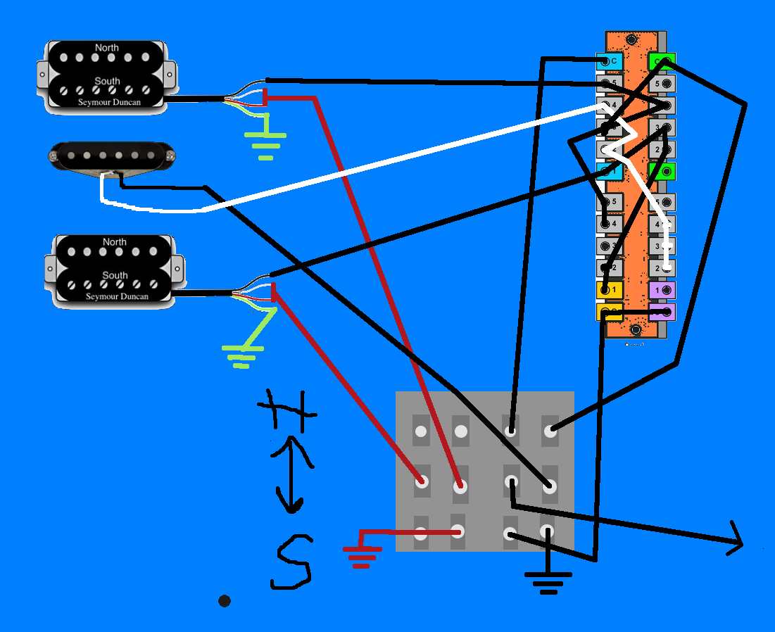 |
|
|
|
Post by newey on Feb 12, 2018 23:00:08 GMT -5
I haven't been able to check them all, but so far I see no mistakes. More to come . . .
Oh, and . . .Hello and Welcome to G-Nutz2!
|
|
|
|
Post by Yogi B on Feb 13, 2018 1:22:39 GMT -5
So, this is my first attempt at making my own Wiring Diagram so i have probably missed something. From what I can see the single coil mode is fine, but the 2, 3 & 4 positions of the humbucker mode don't work as intended. Here's what I think is currently going on there: 2 - Bridge humbucker (Middle shorted)
3 - Bridge humbucker (Middle hanging from hot)
4 - Neck humbucker (Middle shorted)
Fortunately I've done a somewhat similar layout to this in the past, though that had three single coils and phasing. However it still might serve as a starting point, or inspiration. I'll see what I can do. It appears to be essentially the circuit discussed here though without being switched via a push/pull potentiometer. Also I'd guess that the Rothstein version uses a W taper pot (AKA graphic taper, 4b taper, etc.) |
|
|
|
Post by newey on Feb 13, 2018 6:56:51 GMT -5
Spoom, you're new here, and if it comes down to a dispute between what I think and what Yogi B thinks, well, he's smarter than the average bear, and I'm just a doofus. IOW, he's probably right.
But I have to disagree with him.
I see positions 2 and 4 as being OK- middle in series with each HB, respectively. Follow the series chain from the white wire of the middle pup, which connects to hot via the upper left pole of the switch, and the middle black wire gets lifted to connect to the black of each HB via the upper right switch pole. Green of each HB is then grounded, completing the circuit.
But I too see problems at position 3 in HB mode. The pups aren't labelled, but I take the uppermost pickup to be the neck. In that case, I think the neck is connected at position 3, not the bridge. The middle is hanging, as Yogi noted.
Yogi, what am I missing?
BTW, Spoom, it is helpful to label not only the pups in a diagram so that there is no question the page orients as we think it does, but also to label the poles of the Superswitch ("A","B","C" and "D" are the usual way). This facilitates discussion, since we can then call out the lugs as A1, A2 etc.
|
|
|
|
Post by Yogi B on Feb 13, 2018 14:34:15 GMT -5
The issue with the 2 and 4 positions is that the white wire middle of the middle pickup is still also connected to the black wire of the relevant humbucker via the lower half of the superswitch, hence being shorted. I agree with the assumption that the neck pickup is the upper of the two humbuckers (because the fact it is the upper one, the orientation of the single coil, and the switch numbering). However what is happening at position 3 depends on what we think about the two black wires that both cross the '3' terminal of the blue pole. I make it that the shallower of the two (from the neck humbucker) is passing over -- not connected. Whereas, the steeper of the two (from the green pole) is connected (since it actually stops there). Therefore the result of the 3 position is determined by the green pole, which would currently be connected to the lower pickup, assumed to be bridge. I'm curious as to if there is anything like an established convention about this. Is the 'A' pole one of those adjacent to a '1' terminal or a '5' terminal, then from that point do we label the rest horizontally, vertically, clockwise, or counter-clockwise. (I'm assuming the answer is probably no.) |
|
|
|
Post by newey on Feb 13, 2018 16:42:52 GMT -5
I was assuming the opposite, that it connected to lug 3 there. That accounts for the difference in our interpretations of the problem at position 3, but we both agree #3 is a problem. . .
You are correct, I missed that.
|
|
|
|
Post by Yogi B on Feb 13, 2018 23:35:53 GMT -5
I agree with the assumption that the neck pickup is the upper of the two humbuckers (because the fact it is the upper one, the orientation of the single coil, and the switch numbering). About that switch numbering, is it just me or is the switch upside down? For now I've drawn it as is:  Edit: Edit: Updated diagram to no longer unnecessarily short the unused coil. |
|
|
|
Post by reTrEaD on Feb 14, 2018 0:27:25 GMT -5
About that switch numbering, is it just me or is the switch upside down? I don't think it's just you, Yogi. Both switches appear upside-down to me. Not surprising as this was spoom's first attempt. He probably didn't realize that toggles and levers work contrary to the direction of the toggle or lever position. At least your drawing is easy on the eyes which should make following the wiring a less daunting task. Since a full half of the 4PDT switch is dedicated to splitting the 2 HBs and there isn't anything fancy going on like getting hum-canceling with two split HBs in one position while getting hum-canceling with middle and split HBs in other positions, when you get to the final version it might be worth sending just the whites of the HBs to the poles. Then you can connect white to the red for a series link in the HB position and white to ground in the SC position. |
|
|
|
Post by Yogi B on Feb 14, 2018 0:34:08 GMT -5
When you get to the final version it might be worth sending just the whites of the HBs to the poles. Then you can connect white to the red for a series link in the HB position and white to ground in the SC position. I was literally about to note just that in an edit, but then saw this. |
|
|
|
Post by reTrEaD on Feb 14, 2018 0:43:29 GMT -5
Great minds think alike?
|
|
|
|
Post by JohnH on Feb 14, 2018 2:40:47 GMT -5
heres another thread on passive mid circuits: guitarnuts2.proboards.com/thread/7358/passive-mid-boost-cut-circuitAlso check out GuitarFreak on tbe reference section, which has an interactive analysus that can include such things. But seriously, the nicest passive mid control I know of is to engage a series mode (a big mid boost) and dial it back with a 250k pot across one pickup. |
|
|
|
Post by Yogi B on Feb 14, 2018 2:51:56 GMT -5
Maybe not always... For now I've drawn it as is The "it" to which I was refering is the layout (upside-down-ness) of the switch(es), not the layout as a whole. So whilst my verson might not be the final version (because of the flipped switches), it is (hopefully) a fixed version, if that wasn't clear. |
|
|
|
Post by newey on Feb 14, 2018 6:06:48 GMT -5
We've always been a bit shy of HSH designs, so this scheme can and should go into schematics.
|
|
spoom
Rookie Solder Flinger
Posts: 3
Likes: 0
|
Post by spoom on Feb 14, 2018 16:47:52 GMT -5
First of all thanks for all the help and for all the great help on how to make a better wiring diagram (well needed). I really didn't expect this amount help and support. And a huge thank you to Yogi B for the amazing diagram, like really, how do you figure this stuff out, it probably took me 20 minutes to decipher it  Also sorry that I didn't have the time to reply earlier, I had no time left after school, training and sleeping (mostly sleeping to be honest). Now, looking back at my original diagram i do see the problems in position 2, 3 and 4 of the Humbucker mode. I was guessing from the start that there would be problems there but luckily Yogi B (again a huge thank you) made his amazing diagram and solved it all. I was guessing that the switches were put up side down but I didn't worry about it while making the diagram since I was thinking that i could just flip the switches if they were up side down. newey Yes, I was thinking about the upper HB as the neck HB. Now I'm just going to worry a bit about the tone control and then order some parts. P.S Since I'm new to creating threads and such in forums, I do not now how to mention people in my post but I'm guessing you'll see this anyways =) |
|
|
|
Post by reTrEaD on Feb 14, 2018 17:11:54 GMT -5
Hi spoomIf you want to tag someone in a post (this will set a flag which will get their attention) you can click on the icon which looks like this:  As you begin typing their name in the field where it says "Enter a username" some choices will appear. When you've typed enough of their name that their name shows up on the selection list, click on the name. an @username will appear. We should clarify what you want to happen with the two switches. If the 4PDT mini-toggle has its toggle pushed toward the bridge, is that meant to be SC mode? If the 5-position superswitch has its lever pushed toward the bridge, is that meant to select the bridge pickup? |
|
|
|
Post by sumgai on Feb 14, 2018 23:55:20 GMT -5
.... I was guessing from the start that there would be problems there but luckily Yogi B (again a HUGE thank you) made his amazing diagram and solved it all. Don't be too quick to celebrate there bunky, there are still one or two potential problems...
I see that no one has mentioned that the Mid pup has its leads reversed. From the other two pups, we assume that Mid's black is hot, yes? But the Mid's black wends its way toward ground, either through the H/S switch or via one of the two Hb's, and the white is sent to the output where and when needed. Doesn't this present an OoP condition when combined with the other pickups?
sumgai
|
|
|
|
Post by reTrEaD on Feb 15, 2018 1:24:55 GMT -5
I see that no one has mentioned that the Mid pup has its leads reversed. Are you sure about that?  |
|
spoom
Rookie Solder Flinger
Posts: 3
Likes: 0
|
Post by spoom on Feb 15, 2018 11:06:41 GMT -5
Hi spoom We should clarify what you want to happen with the two switches. If the 4PDT mini-toggle has its toggle pushed toward the bridge, is that meant to be SC mode? If the 5-position superswitch has its lever pushed toward the bridge, is that meant to select the bridge pickup? What I wanted was for the 4PDT to be in the HB position when the switch was down or towards the floor. For the super switch I wanted the bridge position to be when the switch is pushed down or towards the floor (like you would wire a standard 5 way switch). I see that no one has mentioned that the Mid pup has its leads reversed. From the other two pups, we assume that Mid's black is hot, yes? But the Mid's black wends its way toward ground, either through the H/S switch or via one of the two Hb's, and the white is sent to the output where and when needed. Doesn't this present an OoP condition when combined with the other pickups?
Are you sure about this? Cause my inexperienced eyes don't see the problems, but as I said I'm inexperienced. Aren't the hot wire from the mid pickup the white, and black ground? Do you mind explaining what you mean with OoP? |
|
|
|
Post by sumgai on Feb 15, 2018 12:13:12 GMT -5
spoom,
OoP means Out of Phase. This gives a rather thin sound quality in parallel, but in series it might be useful... or some folks hereabouts say so. 
Yes, I'm sure. Well, it does depend on our nomenclature, to be sure. 
All we need to do is trace out the two Midle pup leads. Most notably, regardless of mode, Humbucker or Single, the Mid white lead always goes directly to the output in Pos. 2 & 4. From there, tracing out the Mid black lead will show us that it is either going to ground in Single mode, or one of the other two pups in Humbucker mode.... further confirmation of which lead color goes where. This leads us to the quandry at hand.
I dunno about anyone else, but I see no reason within this diagram to call the Mid black wire either 'hot' or 'ground' - we can have it either way. But by convention in the recent guitar world (the last 30 years or more), we call black 'hot'.* Hence, I see an Out of Phase condition here.
Questions?
sumgai
* Actually, it's more of a convention to call White 'ground', and from there, any colored wire that's not white is available to be called 'hot'.
|
|
|
|
Post by sumgai on Feb 15, 2018 12:19:48 GMT -5
spoom, I should add that after we get this logic puzzle solved, then we'll get into your request about that Mid-range tone control. We didn't really mean to sound like we've forgotten that, it's just that we tend to focus on one thing at a time. sumgai |
|
|
|
Post by reTrEaD on Feb 15, 2018 13:29:21 GMT -5
What I wanted was for the 4PDT to be in the HB position when the switch was down or towards the floor. For the super switch I wanted the bridge position to be when the switch is pushed down or towards the floor (like you would wire a standard 5 way switch). Good. I'm pretty sure Yogi was thinking this might actually be your intent. I know that was my suspicion. Yogi made his drawing to follow the pattern set in your original drawing. But that pattern was based on your misconception of which lugs connect in which positions. mini-toggles and lever switches operate from a pivot point. Push the toggle "down" and the lugs on the "upper" portion of the switch are the ones to which the poles will connect. In the current drawing, the functions are opposite of what you want. I'm sure Yogi will flip that around for you. Please note that slide switches and the switches on push-pull pots work in direct fashion. There is no pivot. Aren't the hot wire from the mid pickup the white, and black ground? Basically yes. At least in Seymour's world and you did say you were using SD color codes, right? To clarify, let's use + and - rather than hot and ground. If the string moves toward the pickup, the White wire on the SC would be considered + and the black would be considered - In other words, if the White was connected to hot and the Black to ground, this would result in a positive going signal, as the string moves toward the pickup. Amusingly, the opposite is true on the HB. If the Black on the HB connected to hot and the White to ground, we would get a positive going signal as the string moves toward the pickup. So you had that part right, from the very beginning. In Seymour's world . . . SC: White + Black - HB: Black + White - Red + Green - |
|
|
|
Post by sumgai on Feb 15, 2018 15:13:19 GMT -5
Aren't the hot wire from the mid pickup the white, and black ground? Basically yes. At least in Seymour's world and you did say you were using SD color codes, right? Amusingly, [paraphrased: SD has crapped on their users]: SC: White + Black - HB: Black + White - Red + Green - I for one am not amused. This sort of jiggery is exactly what causes consternation amongst guitar modders. I'll politely leave out any further utterances on this matter. (mic drop) |
|
|
|
Post by Yogi B on Feb 17, 2018 5:00:09 GMT -5
There's another thing we haven't discussed about the middle pickup -- its magnetic polarity. Ideally it would be a south coil, such that the 2 and 4 positions in single coil mode are hum-cancelling (since as it stands the middle is combined with the north (inner) coils of the humbuckers). If not then you might want the humbucker split to the south coils instead. As for re-orienting the diagram, here it is the way I'd normally draw it: 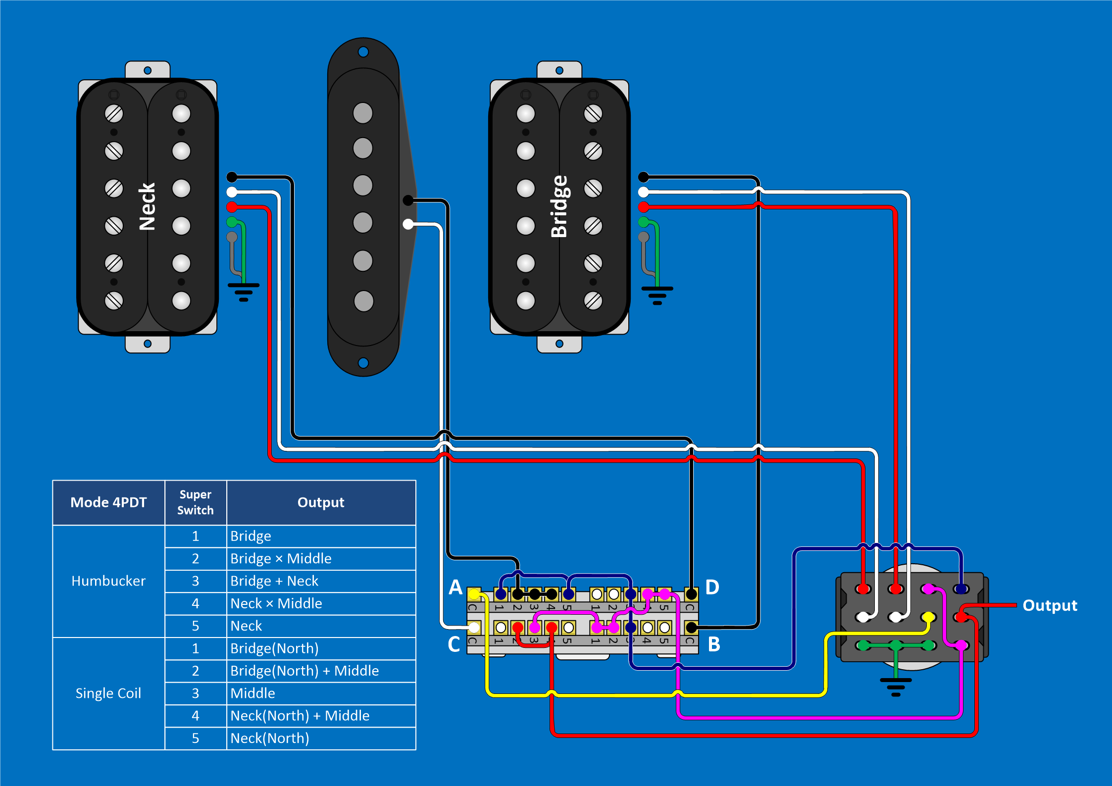 A couple of things to note: - I've kept the A-B-C-D labels consistent between diagrams, hence their peculiar ordering here.
- The A-C end is the upper end of the selector switch, I tend to avoid drawing switches diagonally if I can help it.
- The 4PDT is the same way up as it ever was -- toggle lever down = humbucker mode -- it's just the labelling on the initial diagram that was backwards (if one assumed it to be referring to toggle lever position).
|
|


