lamed
Apprentice Shielder

Posts: 33
Likes: 6
|
Post by lamed on Jul 5, 2019 8:15:18 GMT -5
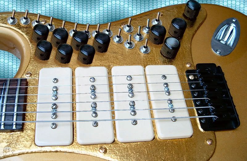
Hi, Though my experience with guitar wiring doesn't go beyond changing pickups, I've been thinking about a rather ambitious project for some times. After some research, I finally came up with a wiring diagram which I think may do what I'm looking for. The idea is to get two completely seperate channels on a dual humbuckers guitar. On each channel, you could set : - neck, bridge pickup, or both; - each pickup wiring, like you would with the Seymour Duncan triple shot (series, parallel, one single soil or the other one); - tone and volume. Then, using one single switch, you could pass from one channel to the other, getting come completely different tones. Here is the wiring I came up with :  The volume/tone wiring is quite classic, so it should be ok if I didn't make a huge beginner mistake. The SD triple shot wiring is documented in several places (including here), so I think I probably got it right too. I'd like to know if this kind of wiring might work. I'm particularly worried about the following things : - when a channel is switched of, a lot of things, including the volume and tone knobs, keep hanging from the hot connector of the jack output. Can this lead to problems? May the knobs have an influence of the sound of the active channel? - 8PDT switches can be pretty expansive. Would a cheap model like this one do the trick : www.jprelec.co.uk/categories/8pdt-slide-switch/product/8pdt-slide-switch/800-907~800-907- fitting all this stuff in a guitar would probably be problematic in itself. My idea would be to get a Squier Affinity Jazzmaster HH, fit SD P-Rails in it then wire it that way, getting a guitar that would both be pretty versatile and look somewhat like a jaguar (I like the look of the bunch of switches)... That would probably mean removing some wood to make more room under the pickguard. How would that affect the tone and robustness of the guitar? Of course, any remark on the wiring would be welcome. In particular, if I got everything wrong and my schematic is rubbish, please tell me. Thanks in advance for your help. |
|
|
|
Post by reTrEaD on Jul 5, 2019 11:18:55 GMT -5
Hello lamed.  to Guitarnuts2. I'm particularly worried about the following things : - when a channel is switched of, a lot of things, including the volume and tone knobs, keep hanging from the hot connector of the jack output. Can this lead to problems? May the knobs have an influence of the sound of the active channel? Yes, the circuit as-drawn would be problematic. For instance, if the right side was selected but the volume for the left side was set to zero, you'd get no sound. That's one of several issues. You can easily cure this by using the poles of your 8PDT more economically. Both Green wires from the pickups ultimately connect to ground, regardless of the position of the 8PDT. So you can save two poles by simply wiring both of the green wires directly to ground. Then connect ONE of the newly liberated poles to the hot of the output jack. Each throw of that pole will connect to the wiper of the appropriate volume control. That appears to be suitable. - fitting all this stuff in a guitar would probably be problematic in itself. My idea would be to get a Squier Affinity Jazzmaster HH, fit SD P-Rails in it then wire it that way, getting a guitar that would both be pretty versatile and look somewhat like a jaguar (I like the look of the bunch of switches)... That would probably mean removing some wood to make more room under the pickguard. How would that affect the tone and robustness of the guitar? Unless you're removing so much wood that the guitar becomes structurally unstable, I wouldn't worry. |
|
lamed
Apprentice Shielder
Posts: 33
Likes: 6
|
Post by lamed on Jul 5, 2019 12:05:35 GMT -5
Both Green wires from the pickups ultimately connect to ground, regardless of the position of the 8PDT. OMG, I didn't notice that...
Thanks for your answer. Here is a wiring modified following your recommandations. Would this work better?
|
|
|
|
Post by sumgai on Jul 5, 2019 12:16:33 GMT -5
lamed,
Hi, and to The NutzHouse! 
When you started out, I thought you were intending a stereo rig, wherein the channels could feed separate amps/pedal boards/etc. Turns out you want a single channel output, but with two presets on the actual pickup selection(s), as well as the Volume/Tone controls. I'd call that something like your average Jazzmaster/Jaguar... on steroids! 
reTrEaD has covered your only true error, that of one channel's controls affecting the other. His solution is non-intuitive, but it works with your current parts selection, so no added cost on your part. But your other question is about the space available for all these new switches. It is my understanding that Jazzmasters (as manufactured by Fender, not necessarily including clones thereof) have a rather large cavity under the pickguard. I really can't say just why Leo mandated such a large carve-out, but there it is. If you choose to go with a Squire of some sort, that may no longer be the case. Even so, from the idea behind the original, full-fledged Jazzmaster, you can be assured that hogging out some wood will not affect the body's stability or performance.
Just to give you a goal as to how to load your axe with controls, try to keep up with The OMGcaster:
HTH EDIT: I see that you've posted a corrected diagram. Insofar as I can see, it looks good to me. As an aside, you've also eliminated any chance of a 'hanging hot' issue. Let us know how it works out, with pictures and sound clips! sumgai |
|
lamed
Apprentice Shielder
Posts: 33
Likes: 6
|
Post by lamed on Jul 5, 2019 12:35:38 GMT -5
Thanks a lot.
As you can see, there's a large piece of wood to remove.
i'll let you know if I get to complete the project. That would take sometime, though, including convincing my wife that yet another guitar is something mandatory...
|
|
|
|
Post by reTrEaD on Jul 5, 2019 12:51:41 GMT -5
Thanks for your answer. Here is a wiring modified following your recommandations. Would this work better? Right idea but I think you have the right-most section of the 8PDT switch selecting the wrong volume controls. When the switch is slid to the left, you're selecting the volume control on the right. I haven't looked carefully at your emulation of the triple-shots with SPDTs to know whether it works or not. If you can afford the slight increase in space, using DPDTs for that purpose will eliminate any possibility of unused coils hanging from hot. The concept can be seen here: guitarnuts2.proboards.com/post/27667/threadLeaving the Black-White coil hanging from hot when the Red-Green coil is selected as a single isn't a huge issue but I prefer to avoid things like that. But if you must use SPDTs rather than DPDTs, I wouldn't let the hanging coil issue be a deal-breaker. |
|
|
|
Post by JohnH on Jul 5, 2019 15:58:04 GMT -5
I reckon you can simplify some more.
Your G pickup wires are always going to ground, so there's no need to have them going there via a switch. Might as well save two poles and then you can use a 6 pole switch.
The only reason that wouldn't work would be if you were doing out of phase wiring, but I don't think you are doing so (and Id agree that you wont need it)
|
|
lamed
Apprentice Shielder
Posts: 33
Likes: 6
|
Post by lamed on Jul 5, 2019 18:01:26 GMT -5
Right idea but I think you have the right-most section of the 8PDT switch selecting the wrong volume controls. When the switch is slid to the left, you're selecting the volume control on the right. Thanks. Seems I did modify my drawing a little too fast. If you can afford the slight increase in space, using DPDTs for that purpose will eliminate any possibility of unused coils hanging from hot. I'll look into your link, as well as the size difference between both type of switches. I'll come with a new schematic in a while. |
|
lamed
Apprentice Shielder
Posts: 33
Likes: 6
|
Post by lamed on Jul 6, 2019 7:02:22 GMT -5
using DPDTs for that purpose will eliminate any possibility of unused coils hanging from hot. I think I understand how it works, but I feel the need to redraw the schematic myself to make sure of it. Is this one correct (each DPDT is enclosed by dotted lines)?
|
|
|
|
Post by sumgai on Jul 6, 2019 10:10:55 GMT -5
lamed, I'm sorry to have to report that your latest diagram won't work, here's the first reason why: Both switches "up" (to the left, in the diagram): B -> nowhere R -> output W -> nowhere G -> ground Net results; nada going out. I stopped there, 'cause I knew you needed help in a more concrete way. So I searched around the basement archives and found this thread, which should help you out. Sadly, none of the particpants ever saw fit to draw a schematic, but I've got a feeling that you're about to correct that.  Go here: SD Triple Shot Switch LogicHTH sumgai |
|
lamed
Apprentice Shielder
Posts: 33
Likes: 6
|
Post by lamed on Jul 6, 2019 10:53:07 GMT -5
Both switches "up" (to the left, in the diagram): B -> nowhere R -> output W -> nowhere G -> ground Here are the wires colors I uses (SD colors):
GREEN = start of adjustable/south coil
RED = finish of adjustable/south coil
BLACK = start of stud/north coil
WHITE = finish of stud/north coil
So this configuration (Red -> output, Green -> ground) should connect south coil in single coil mode. Is it not the case? If not I'm confused.
|
|
Deleted
Deleted Member
Posts: 0
Likes:
|
Post by Deleted on Jul 6, 2019 12:16:09 GMT -5
|
|
lamed
Apprentice Shielder
Posts: 33
Likes: 6
|
Post by lamed on Jul 6, 2019 12:25:08 GMT -5
Hi,
If you want to draw the coils on my circuit, they are BW (black and white) and RG (red and Green), not BR ans WG.
|
|
|
|
Post by reTrEaD on Jul 6, 2019 13:51:41 GMT -5
I think I understand how it works, but I feel the need to redraw the schematic myself to make sure of it. Is this one correct (each DPDT is enclosed by dotted lines)? Hey lamed, I find a convenient way to be certain if a circuit works as intended is to draw a diagram for EACH of the possible switch positions, then draw in the internal switch connection in red. You can then easily keep track of what is connected and what isn't, in each of the separate combination of switch settings. In this case there are two DPDTs, so there will be four drawings. LL LR RL RR If you have time to make the drawings, press on with that. If not, I'll make the drawings tomorrow. |
|
lamed
Apprentice Shielder
Posts: 33
Likes: 6
|
Post by lamed on Jul 6, 2019 14:05:59 GMT -5
Please don't waste your time making diagrams for me. I'll do the work myself. I probably won't have the time to do them until monday but I'll definitly post them.
|
|
|
|
Post by reTrEaD on Jul 6, 2019 14:14:55 GMT -5
Please don't waste your time making diagrams for me. I'll do the work myself. I probably won't have the time to do them until monday but I'll definitly post them. It's never a waste of time to put some effort into teaching someone a new skill. But if you can do this yourself, so much the better. Talk to you again, early next week. |
|
Deleted
Deleted Member
Posts: 0
Likes:
|
Post by Deleted on Jul 6, 2019 15:00:12 GMT -5
Please don't waste your time making diagrams for me. I'll do the work myself. I probably won't have the time to do them until monday but I'll definitly post them. It's never a waste of time to put some effort into teaching someone a new skill. But if you can do this yourself, so much the better. Talk to you again, early next week. I think that was for me  Iamed: you where keen to learn electronic and the drawings, i'll leave you alone. Dont go too crazy as there isnt that much room in a Guitar |
|
lamed
Apprentice Shielder
Posts: 33
Likes: 6
|
Post by lamed on Jul 6, 2019 15:15:24 GMT -5
Angelsbunny, the message was for retread who offered to make the drawings he suggested for me.
I would never be rude to someone who took some time to help me. Please don't take offense.
Also forgive me if I did not choose the correct Words. My primary language is french.I meant that retread was kind enough to review my drawings, he probably had better things to do than work I can do on my own.
|
|
|
|
Post by reTrEaD on Jul 6, 2019 15:29:01 GMT -5
I think that was for me I'm 99.99% certain lamed was talking directly to me when he said "don't waste your time". It seems apparent he would prefer to do the bulk of the work himself and get guidance and confirmation that he's on the right path. We should all respect that and provide the amount of input that solves the problem yet allows him to learn. This is not the first time you've misinterpreted something that was said, and took it personally. And I see you've now deleted your account. Unfortunate, that. But it is what it is. We wish you the best in your future endeavors. And I would suggest you assume the best intent, rather than the worst, if you're unsure of the replies. |
|
lamed
Apprentice Shielder
Posts: 33
Likes: 6
|
Post by lamed on Jul 8, 2019 3:36:47 GMT -5
Hi, Here are the 4 diagrams you suggested to draw. I added the coils to the diagram, as the wires order is misleading. They are grouped by starts of coil/ends of coil instead of the two ends of one coil being side by side. It allows to draw the switches in the same position as on the real triple shot without crossing any wires on the diagram. I feel it's more readable that way, at least for me. In fact, when you solder the wires to a SD triple shot, they are grouped in a similar fashion (WGBR from left to right). Everything seems to work as intended, but maybe I missed some detail. 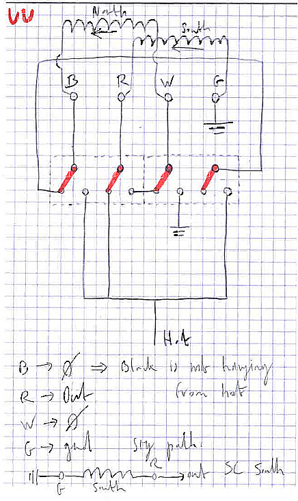 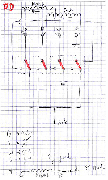 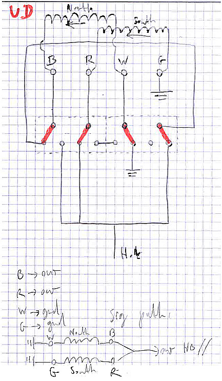 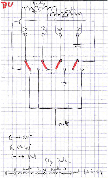 |
|
|
|
Post by reTrEaD on Jul 8, 2019 8:29:49 GMT -5
Well done, lamed. Adding the coils to the drawing improves the clarity. I was hoping you'd include a 'result' path on each drawing and I am pleased to see you did just that. You'll notice the singles occur when both switches are up or down. Both up = South, Both down = North. If that suits you, you have what you need. But if you prefer, you could change the 'direction' on one of the switches to have Parallel and Series occur when both switches are up or down. For instance, one possibility would be: UU = Series UD = North DU = South DD = Parallel You can decide according to what seems most intuitive to you. |
|
lamed
Apprentice Shielder
Posts: 33
Likes: 6
|
Post by lamed on Jul 8, 2019 9:17:55 GMT -5
I would stick with those positions as they are those used by the SD Triple Shots, which I'm already used to (got them in one of my guitars).
As this project would involve buying a new guitar, which the wife would probably frown on, chances are that it will never get completed, but I'm really glad to have been able to conceive the wiring with your help, and learned much in the process. THANK YOU ALL very much for that.
Even as I'm not really intending to implement this project, I could'nt help to look for the place were I could buy a 8PDT switch, and could not find any affordable xPDT switch with x>=7. The only one I found I linked at the beggining of this thread but they don't ship to France under 50 pounds... So that would be another problem.
Anyway, now that I found this board, I'll probably hang arround a little bit here and maybe ask a few questions, as I found much interresting articles to read here. I just read the thread on hum cancelling wich was hugely enlighting. I realize I never really thought about what's happening in a pickup beside "it's induction", which is a shame.
|
|
|
|
Post by newey on Jul 8, 2019 11:14:37 GMT -5
A couple of years ago at Christmastime, I thought I'd treat myself to a new guitar, but I was worried what the wife would think. Then I realized she'd never notice another guitar case. So I just bought it (A Fender Duo-Sonic reissue) and didn't say anything. She only noticed a couple of months ago, and when she asked, I said (truthfully) that I'd had it for years (as in, two years). She is still none the wiser . . . Glad you got the design worked out, and if it ever is built, please post back and let us know! |
|
|
|
Post by sumgai on Jul 8, 2019 11:15:12 GMT -5
lamed,
First, let me just say - job well done!
Next, as reTrEaD noted, adding the coils to the diagram made all the difference in the world. Had you done that in the first place, I would not have given you a thumbs-down in my previous post.
Which of course points out all too clearly my message to another poster - never take so many shortcuts that you obscure your intent. In the case of non-Electrical Engineers (most of the Nutz), that's particularly important. Expressed more succinctly, I'll go right to the guts of the matter - wire colors don't mean a thing in a diagram of any sort. Recall that on any given day, someone is gonna "borrow" your diagram, and no matter how many times you say "I used CompanyX's colors", that statement is gonna get lost in the translation. (Or as in my particular case, it will be ignored.) Always try to be complete, insofar as showing/describing your intentions. Others may not correctly interpret your assumptions.
And finally, lamed, you really need only a 7PDT switch. If you can locate one of those for sale, you should be aware that several of us Nutz in the USA will be only too happy to buy it and have it shipped to our home, and then forward it to you there in France. And I'm sure that we have a few British members that will do the same thing for you. (You did say "under 50 pounds", which I took to mean British pounds sterling.)
Just ask! 
HTH
sumgai
|
|
|
|
Post by reTrEaD on Jul 8, 2019 11:40:21 GMT -5
A couple of years ago at Christmastime, I thought I'd treat myself to a new guitar, but I was worried what the wife would think. Then I realized she'd never notice another guitar case. So I just bought it (A Fender Duo-Sonic reissue) and didn't say anything. She only noticed a couple of months ago, and when she asked, I said (truthfully) that I'd had it for years (as in, two years). She is still none the wiser . . . I sure hope your wife doesn't read this. |
|
lamed
Apprentice Shielder
Posts: 33
Likes: 6
|
Post by lamed on Aug 6, 2019 5:14:24 GMT -5
 I do realize that most people will find it ridiculous and/or cheesy, but I really like the look. Can't understant my wife's lack of enthusiasm for the project. Negociations are still running, though... |
|


 to Guitarnuts2.


 Go here:


