|
|
Post by ourclarioncall on Apr 15, 2020 15:20:22 GMT -5
I was considering if getting some software that can draw schematics might help me to bridge the comprehension gap between wiring diagrams and schematics
My thinking was that if i was able to hand draw a very simple wiring diagram and a schematic at the same time it would help a lot. Then increase the complexity of the circuits little by little , continuing to be able to hand draw both diagram and schematic at the same time demonstrating an understanding
|
|
|
|
Post by newey on Apr 15, 2020 15:55:01 GMT -5
There are several different free schematics software downloads out there, the one I used to use several years ago is no longer supported, and I haven't settled on a new one yet. Most of these are the type of deal where they allow you to use a limited set of tools for free, and if you want the full suite of features, then of course you have to pony up some $$. Or, they let you have a 90-day trial.
For passive guitar wiring, you don't need anything fancy, just the basics will be enough.
You can look around a'web to see what's available, then just play around with the software to see how it works. For most of this, you just drag and drop the individual components you need onto a blank diagram, then draw the connections between them.
Many of these packages, in the advanced versions, allow one to do a virtual "circuit test" of the schematic, to see output voltages and so forth, but you won't need anything like that just to learn to "speak schematic". Also understand that, while most schematic symbols are standardized, there are some variations, for example, resistors are typically shown as a jagged line between two connectors, but sometimes shown as a rectangle between 2 connectors.
|
|
|
|
Post by ourclarioncall on Apr 15, 2020 20:42:51 GMT -5
Cheers Newey
Good info as always 👍
|
|
|
|
Post by sumgai on Apr 15, 2020 23:06:37 GMT -5
occ, What you're doing now is drawing layout diagrams by hand. What's to say that drawing a schematic by hand is any different? (Many of your fellow Nutz do exactly that.) My opinion is that you're setting yourself up for even more frustration if you try to use software to take the place of what you can easily do by hand. All you need at this juncture is a schart that shows you the schematic symbol for each component, and you're pretty much set. This first link is rather overly full of symbols you don't need, but everything you do want is in there: Chart of schematic symbolsThis next link is a near duplicate, laid out a little differently. But I include it not for the symbols, but for the "Reference marks" that are also used in schematics, i.e. identifiers such as L for inductor (or coil), C for capacitor, and S for switch. Again, more info than you'd ordinarily need here in The NutzHouse, but everything you'd ever see here, it's in this link: Chart of reference identifiersThat's a pretty good start, I should think. But when you're ready to graduate from hand drawings to more neat-appearing drawings, then a piece of software will be a nice thing to have. BTW, you might ask JohnH for a hint as to how he does his drawings in MS Word.  HTH sumgai |
|
|
|
Post by newey on Apr 16, 2020 6:17:01 GMT -5
You said software, so that's where my thought process went, but sg is right, probably easier just to draw it for starters. After my post here, I took a look at what was available for free, and downloaded an open-source program called Fritzing. This seems to be much more complex than needed, it is heavily biased towards breadboarding PCBs and it is difficult to sort through the thousands of IC chips, relays and so forth that one would probably never need in a guitar. And I still haven't figured out how to edit parts or labels, etc. But I did a simple module, as a learning experience. See if you can ID the various components, and tell us what the module does. Maybe even translate it into a wiring diagram. Understand that this is not a complete scheme, but only a portion, a module of part of a guitar's wiring. 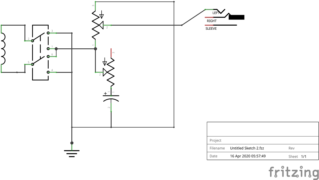 |
|
|
|
Post by asmith on Apr 16, 2020 7:49:51 GMT -5
FWIW here was my media and method when I spent time figuring out wiring diagrams. 1. Pen and paper — and I thought pen was better than erasable pencil. Using pen forced me to think about a whole scheme's operation from scratch every time, instead of progressively eking a scheme's separate parts. This always forced me to reconsider my assumptions about wiring every element of a circuit. Example: here's a crackpot diagram of a 2-pole, 2-throw switch, the kind you find attached to the bottom of "push-pull pots:"  The circles with the thick lines jutting out are the 2 poles, which each alternately connect between the 2 circles below them (the possible connections are called "throws"). The grey dashed line indicates that the poles always move in tandem between their connections. There are two ways of wiring this switch up to provide an "Out of Phase" circuit for a pickup:   They look almost identical, but when placed inside a scheme with other modules, e.g. volume and tone controls, each offers different possibilities in switching schemes. If you settle on one 'wiring way,' but have to draw it out again each time you draft the circuit, you're going to re-examine it enough that you start questioning whether one way is better than the other. This continual re-examination provides many opportunities for you to be creative with the wiring. Otherwise, if you just used a computer program to design switching schemes, you might draw the first 'wiring way' and simply copy and paste it between scheme drafts, never realising that using the second 'wiring way' was key to your scheme. Using pen and paper forces this re-examination. 2. Progress to pen and paper with printed component diagrams, i.e. diagrams of the stuff that cannot change from draft to draft. For example, here's a crackpot diagram of a 4-pole, 5-throw "5-way superswitch."  The switch cannot (generally) be modified like your wiring scheme can, and so redrawing it every time doesn't offer opportunities for creativity; it's just a chore. If you print out ten A4 pages with that image on it, being creative with where wires, pickups, and components go is a lot easier than if you had to draw out the switch every time. 3. Computer graphics programsOnce you have the general scheme finished, you can transfer it over to computer graphics, neatly drawing up your scheme in an appropriate program. Vector graphics program Inkscape, the "free Illustrator," is my starting recommendation. The process of neatening your scheme into a clear, consistent diagram is good opportunity to revise and double-check it. Afterwards, you can further check which parts of your circuit are active at different configurations of the circuit's switches, using the computer program. Example:   Here, using the program, I "painted over" two possible switch combinations in this circuit, to double-check which components were active in those combinations. And if it turns out you made a mistake, back to your pen and paper. |
|
|
|
Post by ourclarioncall on Apr 19, 2020 16:28:05 GMT -5
newey i have to admit I struggled lol. And am still not confident I got it right. But it seems that the components are inductor/single coil , dpdt toggle , potentiometer/volume , another pot with cap(polarised? for a reason or just what the programme let you use?) , output jack (threw me here is there are 3 (terminals?) instead of the 2 that I’m used to seeing (hot and ground/signal and return) i was having a look at a few other guitar schematics tonight and found them a touch easier to understand. I guess there is a bit of variation between software and layout on screen . if I have connected everything right then I can only understand it as an out of phase switch with volume and tone for 1 single coil i wasn’t sure if the terminals on the pots were number 1,2 and 3 from left to right or right to left . I assumed left to right as I’m familiar how a volume pot on a strat is wired. Also the cap would usually be soldered to the back of the pot ? I did not do that in my pic , nor soldered lug 3 to the back of the pot, nor used the back of the pot as a place to ground everything, I just drew them going straight down to the output jack. earlier I was second guessing and thinking it can’t be an out of phase as there is only one pickup so thought it might have been a blower switch to bypass vol and tone. but then you said it’s part of a module so it’s likely there will be more can one pickup so and out of phase is possible. anyway, the exercise was good for me although it affirmed what I already knew, that I was out of my depth with this one lol, but it’s good to be throw in the deep end now and again, so thank you for taking the time to give me a swimming lesson 🤗 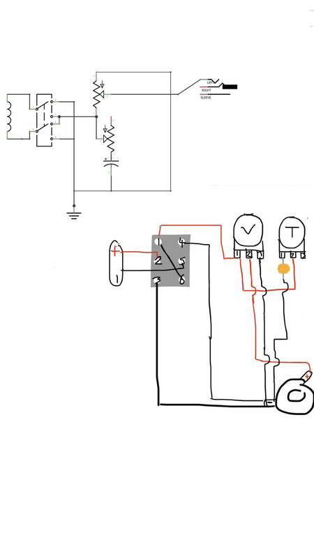
|
|
|
|
Post by ourclarioncall on Apr 19, 2020 16:45:15 GMT -5
sumgai asmith thanks guys, yeah, good advice, pen and paper seems like a quicker ,less frustrating, more productive way to go. Then use that type of software once you have the finished article or have a decent grasp on what your trying to layout. I did computer graphic design years ago so am familiar with vector graphic software which I use to make sheets for guitar teaching , so that’s another option. im sure I’ve used Inkscape at some point
|
|
|
|
Post by sumgai on Apr 19, 2020 19:50:34 GMT -5
occ, Your wiring diagram looks good, it follows the schematic exactly. And you've already noted that you didn't take any shortcuts (such as making the wiring "X" on the DPDT switch itself), but that doesn't alter the fact that your diagram will work as advertised. While I like that you have numbered the switch terminals correctly, I'm not happy about the direction of those arrows next to each pot. In the guitar world, they do indeed mark the direction of travel for the maximum intended effect (max volume, max tone cut), which is to say, one will be at 10 on the knob and other at 0. Not consistent, eh? Worse, what we see and use isn't necessarily true for other disciplines. Unless the software allows one to place the arrows facing the desired direction? So, a couple of things for you to jot down in your notebook: A) The jack is indeed a three-conductor jobbie. But the label that says "RIGHT"... that's wrong - it should say "RING". This gives us Tip, Ring, Sleeve, or TRS for short. That particular jack type was purloined from the days of stereo headphones, wherein the third conductor (Ring) carried the Right channel, and the tip carried the Left channel. Nowadays, we use this jack (and it's found doing the same job in many other fields of endeavor) to control battery power to a circuit. Essentially, when a standard (mono, two conductor) plug is inserted, the sleeve of the plug is shorting the Ring terminal to the Sleeve of the jack, right? Well, if the battery's negative terminal is connected to the Ring terminal on the jack, then every time the plug is inserted we'll see the circuit of battery-negative -> Ring terminal -> Sleeve terminal -> ground is completed, and the circuit comes on. Very obviously, removing the plug turns the circuit off. and; B) The cap is indeed polarized. I'll not go into all the whys and wherefores, but in essence, the plus sign means that you place it into the circuit such that any positive DC voltage will meet the positive terminal. If you really need the down-and-dirty, I'll spring for it, but not just now. I can't say as I'm enamored of the resulting schematic diagram (from Fritzing), but I've certainly seen worse. Welcome to the head of the class!  sumgai |
|
|
|
Post by newey on Apr 20, 2020 5:42:21 GMT -5
Correct.
And, you correctly sussed that the inductor symbol represents a pickup coil. In essence, a pickup coil is an inductor.
Correct. After I posted it, I realized I failed to connect the output jack sleeve to ground And sumgai is right, I also forgot to "flip" the pots so that the arrow was the right way around. (or, I could have wired it the other way around) I also forgot to erase the "+" sign on the cap, so it shows as polarized. That's what I get for speed. . .
Whether the pots terminals are labelled as "1-2-3" or "3-2-1" depends on whether the diagram shows the pots from the bottom or looking down from the top. The convention in guitar wiring diagrams is to show the pots from the rear, since that is what one will be looking at while wiring them.
My diagram thus has it backwards, mainly because I didn't notice the tiny numbers. Typically, the CCW lug is numbered "1" and is to the left of the wiper when the pot is oriented so that the shaft is pointing up, and with the solder lugs pointed toward the observer.
The CCW lug, or the "1" lug, will be wired to ground when the pot is used as a volume control. The CW lug, #3, will ordinarily be the "hot" input, unless one is using an alternate wiring.
|
|
|
|
Post by perfboardpatcher on Apr 21, 2020 13:50:40 GMT -5
I was considering if getting some software that can draw schematics might help me to bridge the comprehension gap between wiring diagrams and schematics My thinking was that if i was able to hand draw a very simple wiring diagram and a schematic at the same time it would help a lot. Then increase the complexity of the circuits little by little , continuing to be able to hand draw both diagram and schematic at the same time demonstrating an understanding I myself use xfig in linux. It doesn't have a steep learning curve, it's not too difficult to create symbols and to create schematics with these symbols. I don't know winfig, but it could be a good alternative in Windows. At winfig.com/ it says: "WinFIG is a vector graphics editor application. The file format and rendering are as close to Xfig as possible, but the program takes advantage of Windows features like clipboard, printer preview, multiple documents etc." |
|


