Deleted
Deleted Member
Posts: 0
Likes:
|
Post by Deleted on Apr 21, 2020 12:24:06 GMT -5
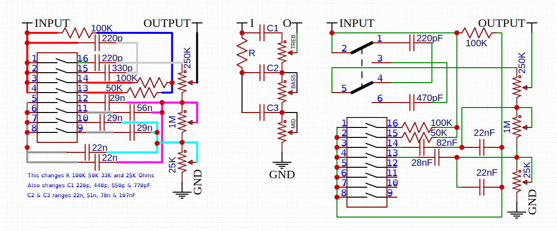
 I can change a lot of things, but this circuit has so much of range its hard to follow all areas. The way i do things i can tend to change Areas To make it simple gotta figure out what the Best settings are for Treble, Middle, Bass at HIGH and LOW settings for each of them and try and blend them all Tone Stack CalculatorBeen looking at the graph for a few hours now .. think im going BLIND from it |
|
|
|
Post by sumgai on Apr 21, 2020 15:07:56 GMT -5
'bunny, I can easily follow what you've done, and what you think you've done, but to kind about it, your circuitry "needs more cowbell".  Let me point out two errors to begin with, then I'll turn it back over to you. 1a) Looking at the left-most diagram, and following the input line along towards the Treble pot, we see that if no switches are closed, then no signal will get to the pot. Maybe you'd be fine with a "radio silence" condition, but I'm betting that most players will be less than thrilled about this. So, looking to see which switch will complete the circuit, it turns out that only 1-16 will take incoming signal and route it through to the Treble pot. If you turn on anything else whilst leaving 1-16 off, then nothing happens. Seems like a whole lot of things depend on just that one switch being closed - so why have it in the first place?  1b) If you close 2-15, the 220 and 330 caps don't do anything - they're effectively shorted by 1-16. In short, your table of possible values is highly suspect. 2) The resistors (100K in series with 100K, 50k, or both in parallel) go to the top of the Treble pot through the 220 cap, provided that 1-16 is closed. That's not according to Hoyle, is it?  In point of fact, regardless of the switch positions (excepting 1-16), the Bass and Mid controls never get any signal at all. With 1-16 closed, the bottom of the Treble control will provide a greatly reduced amount of signal to the remaining two pots, but if the Treble pot is turned down even part way, then they'll simply act like volume pots!  You were right about one thing though.... you can change a lot of things. Now is as good a time as any to get busy with that, eh?  (I've not looked at the right-side diagram, I figure that one set of errors is enough for one day's analysis.  ) HTH sumgai |
|
Deleted
Deleted Member
Posts: 0
Likes:
|
Post by Deleted on Apr 21, 2020 15:22:21 GMT -5
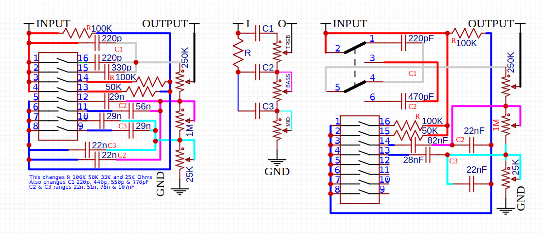
'bunny, I can easily follow what you've done, and what you think you've done, but to kind about it, your circuitry "needs more cowbell".  Let me point out two errors to begin with, then I'll turn it back over to you. 1a) Looking at the left-most diagram, and following the input line along towards the Treble pot, we see that if no switches are closed, then no signal will get to the pot. Maybe you'd be fine with a "radio silence" condition, but I'm betting that most players will be less than thrilled about this. So, looking to see which switch will complete the circuit, it turns out that only 1-16 will take incoming signal and route it through to the Treble pot. If you turn on anything else whilst leaving 1-16 off, then nothing happens. Seems like a whole lot of things depend on just that one switch being closed - so why have it in the first place?  There is a 220pF going to the Treble Pot, the switchs 1/16 and 2/15 will just add to this Cap Value range of 220p-770pF (should be a RED DOT joining the grey connections) basically does what the C1 does There is a 220pF going to the Treble Pot, the switchs 1/16 and 2/15 will just add to this Cap Value range of 220p-770pF (should be a RED DOT joining the grey connections) basically does what the C1 does1b) If you close 2-15, the 220 and 330 caps don't do anything - they're effectively shorted by 1-16. In short, your table of possible values is highly suspect. It should SUM the Caps 220p 220p and 330pF !! C+C+C2) The resistors (100K in series with 100K, 50k, or both in parallel) go to the top of the Treble pot through the 220 cap, provided that 1-16 is closed. That's not according to Hoyle, is it?  Dam it that is Wrong down there, the BLUE should Hook up to the at the bottom left ( Pin 5,6,7, 8 ) Dam it that is Wrong down there, the BLUE should Hook up to the at the bottom left ( Pin 5,6,7, 8 )
Basically changes what would be R, from 100K, 50K and 25k it think maybe 33k i cant remember now
1/((1/R)+(1/R)+(1/R))In point of fact, regardless of the switch positions (excepting 1-16), the Bass and Mid controls never get any signal at all. With 1-16 closed, the bottom of the Treble control will provide a greatly reduced amount of signal to the remaining two pots, but if the Treble pot is turned down even part way, then they'll simply act like volume pots!  You were right about one thing though.... you can change a lot of things. Now is as good a time as any to get busy with that, eh?  (I've not looked at the right-side diagram, I figure that one set of errors is enough for one day's analysis.  ) HTH sumgai 1/16 2/15 changes the C1 (C+C+C) 3/14 4/13 changes the R (NOT that the BLUE should be hooked up to 5,6,7 and 8) 1/((1/R)+(1/R)+(1/R)) 5/12 6/11 changes the C2 (C+C+C) 7/10 8/9 changes C3 (C+C+C) 
the way i do and trick things i can change C1,C2,C3 as the RV change May have to go back to basic and filters, im not sure the logic on the mid control seems to leave a Saggy One Butt Cheek look |
|
|
|
Post by sumgai on Apr 22, 2020 12:57:50 GMT -5
I see that you've changed the diagram around a bit. I'll look at it again later on today, right now I've got quilts to get out the door. Seems like my "job" isn't suffering so much from the lockdown.  |
|