clayton
Rookie Solder Flinger

Posts: 2
Likes: 0
|
Post by clayton on Jun 5, 2020 6:32:25 GMT -5
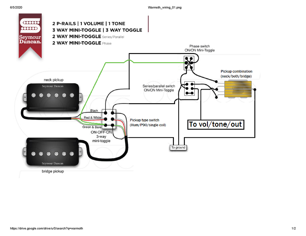
Hi, I have a specific p-rail switching design in mind and I'm wondering if my wiring diagram is correct. I cut and pasted together a schematic (attached) that's essentially a combination of 2 SD diagrams: this one for pickup type switching and this one for series/parallel and phase switching. Without the use of push/pull pots, I'd like 4 toggle switches: 1. Pickup type (humbucker/P90/rail) 2. In/out of phase 3. Series/parallel between the 2 pickups 4. Pickup combination (neck/both/bridge) I understand how to wire the volume, tone, and output, but am not sure if the wiring between the pickups and the pickup combination toggle is correct, e.g. I'm not sure about the extra green wire between the pickup type toggle and the phase toggle. Will this wiring work? Thanks   |
|
|
|
Post by reTrEaD on Jun 5, 2020 9:11:14 GMT -5
Hi clayton and  to Guitarnuts2. There are a few problems with your design which will prevent it from working as intended. The green and bare from the Neck pickup are permanently connected to ground. This will be a huge problem when putting the neck pickup out of phase. - You should remove the jumper between the lower left and lower right lugs of the 'Pickup Type' switch. - You should also connect the bare wire from the Neck pickup to the lower right lug of the Pickup Type switch. Also there will be a dead spot when the Series/Parallel switch is in the Series position and the Pickup Combination switch is in the Bridge position. You need to rethink the way you wire these switches together. This thread will help you understand the concept involve in getting these two switch to work properly: 3-way + Global Series switch the GuitarNutz (proper) wayIn your design you'll want one pole of the Series Override switch connected to the Bridge lug of the Pickup Combination switch and the other pole of the Series Override switch will be connected to the lower left lug of the Phase Switch. But if you understand the concept, you should be able to reason out where the other lugs of the Series Override switch should be connected. |
|
|
|
Post by newey on Jun 5, 2020 9:41:14 GMT -5
Clayton-
Hello and Welcome to G-Nutz2!
I'm fairly sure we can get to where you want to be with 4 switches, but maybe not those particular 4 switches. But, to answer your question, there are a number of problems with your diagram (There may be more problems than this, these are the ones I spotted at first glance):
First, the "Pickup type Switch" is not (necessarily) mis-wired, but it is mis-labeled. As shown, the HB position will be in the middle, with the P-90 at one end and the rail at the other. (I don't know which is which because I don't know which wire pair is for the P-90 vs. the rail). But if you demand that the HB be at an end rather than in the middle, the switch will probably need to be an On-On-On rather than an On-Off-On, and rewired to boot. (Also, since both the P-90 and the rail are single coils, it's a bit confusing to call it a single coil rather than calling it a "rail".)
Nomenclature aside, your phase switch won't work. In order to swap the phase, both the + and - connections must be swapped. In your diagram, the neck green wire is permanently grounded at the HB/P90/Rail switch. That wire then runs to the phase switch, meaning that flipping the phase switch will ground all output from the neck pickup.
Also, the series/parallel switch won't work as shown. A series connection between two pickups requires that one of the two pickups not be permanently grounded- one ground has to be "lifted" by the switch. On your diagram, the series/parallel switch only switches the two + (i.e., black) wires- both green wires are permanently grounded at the pickup type switch.
I'm not sure off the top of my head how to rewire the series/parallel and pickup type switches to solve this, I'll have to take a closer look (and the input of others would help as well). But you may need to have a switch with more poles to solve the interaction between the "pickup type switch" and the series/parallel switch. Or, if you can add a fifth DPDT switch, so that each pickup has its own HB/P90/rail switch, that would solve things.
But maybe it can be done with just the switches you show, I may be missing it
|
|
clayton
Rookie Solder Flinger

Posts: 2
Likes: 0
|
Post by clayton on Jul 8, 2020 21:09:29 GMT -5
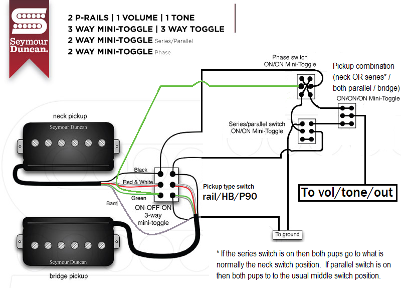
![]() Thanks for the tips! I think I fixed the issues - does the attached diagram make sense now?  |
|
cokolisko
Rookie Solder Flinger

Posts: 1
Likes: 0
|
Post by cokolisko on Sept 18, 2021 8:43:47 GMT -5
Do you have this wiring diagram without the phase switching. I’m looking to do something very similar but I have not interest in the out of phase sounds. Can it be done to have the 3 or 4 main P rail sounds, and then have a switch that controls whether the 2 pickups are playing in series parallel. Ideally I’d be using a 3 way slide switch (dp3t) to control the p rail sounds, and a single on/on toggle for the series/parallel. Thanks
|
|
|
|
Post by newey on Sept 18, 2021 10:32:36 GMT -5
cocolisko-
Hello and Welcome to G-Nutz2!
Unfortunately, no one responded to clayton over a year ago, so his diagram has not been properly vetted. OTOH, we never heard back, so if there were issues, presumably he'd have posted something. But that's just a presumption. At first blush, however, it looks OK to me.
The phase switch is a separate module that can be easily removed from this scheme. The black wire which connects to the middle right-side lug of the phase switch will just connect to the 3-way pickup selector instead, and the green wire will connect to the middle lug of the series/parallel switch.
The series/parallel set-up that clayton is using isn't, to our way of thinking, the best way to do this. As clayton has it, the series setting only works when the 3-way is set to the neck position. The link above that RT posted is the better way- the series/parallel switch overrides the 3-way, so that flipping to series gives you both pickups in series regardless of the way the pickup selector is set. But that's a matter of your preference, up to you how you do it.
I suggest that you redraw clayton's diagram without the phase switch, you'll have a better understanding of what you are doing and we will then focus on your diagram, making sure it's good to go.
|
|
sorryhero
Rookie Solder Flinger

Posts: 1
Likes: 0
|
Post by sorryhero on Aug 27, 2022 11:22:19 GMT -5
I know this is old, but I’m looking to do something very similar and am curious if this got solved. My situation is slightly different and I’m trying to draw it up right now. I’m an electrician who knows enough about controls to get through most of my projects, this one is just a little ambitious. I’ll post my idea soon, but I have:
2 p-rails
2 mustang 3way sliders (dp3t one for each pickup)
2 on on sliders for series parallel and phase (dpdt)
3way tele style pickup selector
I’m also thinking about adding a mini toggle and using different values of tone caps but that’s easy
|
|
|
|
Post by newey on Aug 27, 2022 12:20:45 GMT -5
I know this is old, but I’m looking to do something very similar and am curious if this got solved. What you see above is all the further we got with this. Never heard back from clayton or cocolisko. But if you take a stab at the diagram of what you want we should be able to sort it for you. It sounds like it should be doable, will just need to adapt it for the slide switches. Note that it is a bit odd to speak of a slide switch as being a "DP3T" (although technically correct); it has 2 poles but no common lugs. |
|