abou
Rookie Solder Flinger

Posts: 9
Likes: 0
|
Post by abou on Oct 6, 2020 14:04:42 GMT -5
Hello every one ! I'm building a tele guitar, and I would like to have some nice electronic feature. Like a low cut on a mini toggle switch (+-160Hz), and the possibility to switch 50s/modern wiring via a mini toggle switch too. With a Schaller megaswitch M. But I really don't know how to configure it right, and which cap to choose. Here is the incomplete wiring diagram... if some one could help me to fill it, it would be very appreciated ! :-) Amaury 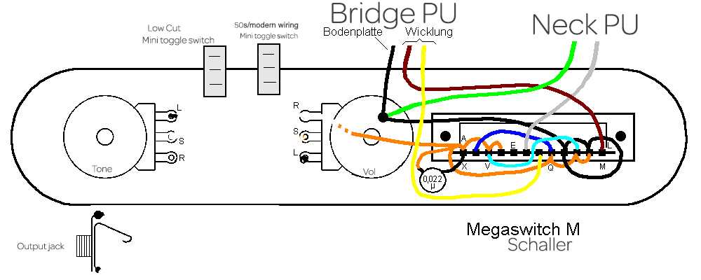 |
|
abou
Rookie Solder Flinger

Posts: 9
Likes: 0
|
Post by abou on Oct 6, 2020 14:06:19 GMT -5
Here is the original wiring diagram from Schaller... 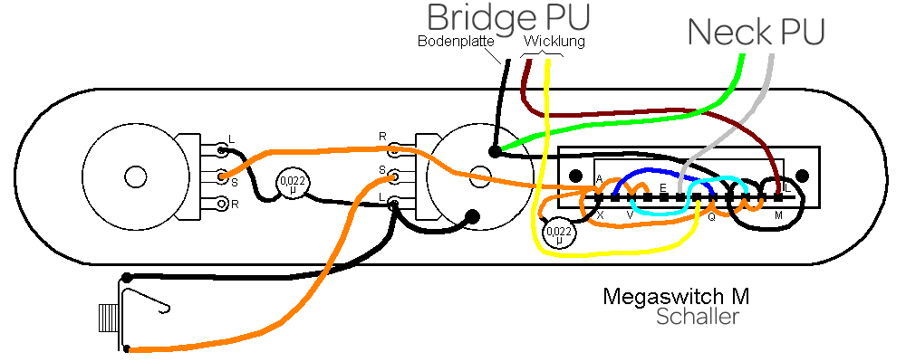 |
|
|
|
Post by newey on Oct 6, 2020 18:09:07 GMT -5
abou-
Hello and Welcome to G-Nutz2!I'm sure we can help with this. I haven't looked back into the archives to review the switch logic of the Megaswitch M, but I'm assuming that portion of the diagram you have lifted directly from the Scaller diagram, with no changes- so it ought to work. Although you didn't say what pickup combos were intended for the various positions. . .  However, one comment: What type of mini-toggle switches do you have? Your diagram depicts each one as having only 3 lugs (i.e., connections). That implies these are single-pole switches (SPDT). That type of switch would be OK for the bass cut, but as for the other, to switch between '50s and modern wiring of the tone pot will mean switching 2 wires independently. You will need a double pole switch to do so, since you will be switching 2 things at once. |
|
abou
Rookie Solder Flinger

Posts: 9
Likes: 0
|
Post by abou on Oct 7, 2020 9:19:20 GMT -5
Thanks for the welcome, and your comments ! Yes the right part of the diagram comes from Schaller's web site. Here are the combinaisons of the megaswitch M with 2 single coils: 1 bridge 2 bridge and neck out of phase parallel 3 bridge and neck in phase parallel 4 bridge and neck in phase in series 5 neck For the toggle switches, I have one SPDT at the moment (for the low cut as you said), now I know I will need one DPDT for the 50s/modern tone wiring, thanks. Here is a new design with the mod you talk. 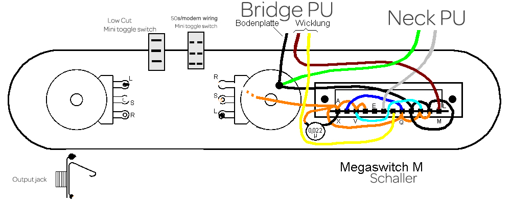 |
|
|
|
Post by ashcatlt on Oct 7, 2020 13:49:58 GMT -5
...to switch between '50s and modern wiring of the tone pot will mean switching 2 wires independently. You will need a double pole switch to do so, since you will be switching 2 things at once. I don’t believe that to be true. Aren’t we just switching which lug of the V pot we’re connecting the T pot to? That’s one wire from the T pot between two positions, no? |
|
abou
Rookie Solder Flinger

Posts: 9
Likes: 0
|
Post by abou on Oct 7, 2020 16:15:27 GMT -5
Here is a 50s/modern wiring diagram, with toggle switch, I found on the internet. 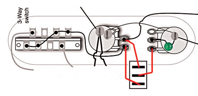
And a low cut  |
|
|
|
Post by reTrEaD on Oct 7, 2020 19:24:01 GMT -5
Here is a 50s/modern wiring diagram, with toggle switch, I found on the internet. Hi abouThe switching between 50s and modern tone control is correct for a circuit without a low-cut filter. When you add your low-cut switch, the wire from the bottom lug of the 50s/modern switch that currently goes to the CW lug of the Volume control will instead go to the pickup selector switch. The low-cut circuit is all kinds of wrong. Don't even think about doing it that way.Instead, just place a capacitor in series with the wire going from the pickup selector to the CW lug of the Volume control. A SPDT switch in parallel with the cap will defeat the low-cut when the switch is closed and enable the low-cut when the switch is open. For the value of the cap, use a RC filter calculator. First determine the value of the resistance by calculating the parallel combination of the Volume control and the input impedance of the amplifier. For a 250k volume pot and a 1M input impedance, that would be 200k. If you want LF rolloff with a 160Hz corner frequency, the cap should be approximately 5nF (.005uF) |
|
abou
Rookie Solder Flinger

Posts: 9
Likes: 0
|
Post by abou on May 26, 2021 4:44:14 GMT -5
Hi ! Thanks for the infos ! I finally find the time to achieve my project. I used this diagram: 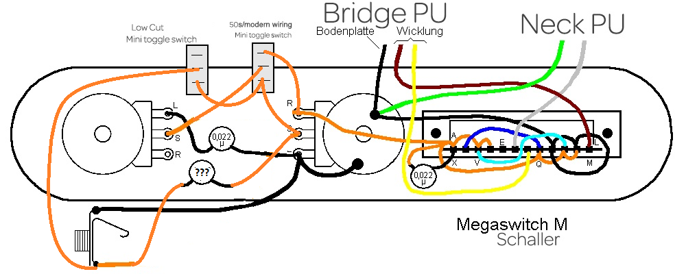 And unfortunately it doesn't work like it should. The 2 mini toggle switches are totally ineffective, and the positions of the 5way switch are not ok. I should have: 1 bridge 2 bridge and neck out of phase parallel 3 bridge and neck in phase parallel 4 bridge and neck in phase in series 5 neck And I have: 1 bridge 2 neck with no treble 3 bridge and neck: parallel or serie I don't know 4 bridge 5 neck Has someone an idea to solve the situation ? :-) Cheers Amaury |
|
|
|
Post by thetragichero on May 26, 2021 13:04:37 GMT -5
you can diagnose whether series or parallel by taking a dc resistance reading on the output with the pots at max. that should help the fellas who are better at switching logic determine what you've got going on
|
|
|
|
Post by newey on May 26, 2021 13:13:56 GMT -5
Please test the resistance, as tragichero suggests, not only at position 3 but in all the switch positions. Also, please perform a "screwdriver tap test" to be sure that you are truly getting the pickups you have listed in each position.
|
|
abou
Rookie Solder Flinger

Posts: 9
Likes: 0
|
Post by abou on May 28, 2021 7:45:34 GMT -5
Yes i've made the screwdriver test.
Here is what I have with a multimeter:
1 bridge: 6,52
2 neck with no treble: 7,21
3 bridge and neck: parallel or serie I don't know: 3,48
4 bridge: 6,52
5 neck: 7,21
It is Lindy Fralin stock tele PU: in theory 6.9 kOhm for the bridge PU and 7.4 kOhm for the neck.
|
|
Deleted
Deleted Member
Posts: 0
Likes:
|
Post by Deleted on May 28, 2021 11:55:47 GMT -5
|
|
|
|
Post by thetragichero on May 28, 2021 23:35:21 GMT -5
3 is definitely parallel as is so you can look at the other position wirings that are not to your liking
|
|
Deleted
Deleted Member
Posts: 0
Likes:
|
Post by Deleted on May 29, 2021 7:37:42 GMT -5
I was going off the maths 1/((1/Neck)+(1/Bridge)) If in series would be Neck+Bridge SS3 (bottom of the link) Bridge Bridge and neck reverse phased and parallel Bridge and neck phased and parallel Bridge and neck phased and in series Neck schaller.info/media/image/63/60/bb/SS3C.png |
|
|
|
Post by newey on May 29, 2021 8:08:22 GMT -5
So, you are missing the neck pickup OOP at position 2 and missing the bridge pickup in series with the neck at position 4. This suggests there are 2 separate issues going on.
The neck pickup is permanently grounded in this scheme, so the problem at position 2 would have to be a problem with one of the neck hot leads between the poles of the Megaswitch. Recheck all those connections, maybe hit them with your soldering iron to remelt the solder at each end of the connections.
On the problem at position 4, it could be either end of the bridge pickup, so same thing there but do the ground connections as well.
|
|
|
|
Post by Yogi B on May 30, 2021 6:07:39 GMT -5
Here is what I have with a multimeter: 1 bridge: 6,52 2 neck with no treble: 7,21 3 bridge and neck: parallel or series I don't know: 3,48 4 bridge: 6,52 5 neck: 7,21 Given which positions have problems (the series and (half) out-of-phase settings) and this being a Tele my first instinct is that the shield ground hasn't been separated from the pickup 'negative'. Looking more closely at the diagram that would appear to be consistent with the results you're getting -- so that's my suggestion of what to check. Both Tele pickups usually have a connection between the end of the coil intended to be soldered to ground and the metal content of the pickup (i.e. the bridge's baseplate & the neck's cover). This is fine for the standard wiring scheme, but becomes a problematic when using series or out-of-phase wirings resulting at best in extra noise or as in this case the output from a pickup being unwantedly short-circuited. Therefore in order to properly use such schemes, this connection must be removed from the appropriate pickup (which varies depending on the design of the particular scheme). For Schaller's diagram it's the bridge pickup -- you'll note that it's shown with three wires: brown and yellow marked "Wicklung" (winding); and a separate black wire marked "Bodenplatte" (baseplate). Fralin has an article describing this (albeit for the neck pickup) but the process is essentially the same for either pickup. (Unfortunately the only demonstration I can find which features a bridge pickup is from PremierGuitar, and I'm loath to link to a DW article.) If none of the above is new information to you and you've already cut the connection to the baseplate, use your multimeter to double check that there isn't direct continuity between the baseplate and coil 'negative' (you should do this test when in position 2 or 4).
Also, something I noticed with your description: I should have: 1 bridge 2 bridge and neck out of phase parallel 3 bridge and neck in phase parallel 4 bridge and neck in phase in series 5 neck In Schaller's diagram (despite what is listed on their site), position 2 is actually specifically parallel half-out-of-phase (PHOoP) as evidenced by the presence of the capacitor attached to the switch in that position. This cap, being in series with the bridge pickup cuts its bass output (much like your low cut switch), but because of the parallel arrangement in also causes some loss to the neck pickup's mids -- in reality however, because the pickups are out of phase, these cuts result in a somewhat thicker tone (than normal, fully, OoP), as the (non-overlapping) cuts to both pickups result in less cancellations. |
|
|
|
Post by reTrEaD on May 30, 2021 21:30:50 GMT -5
Hi ! Thanks for the infos ! I finally find the time to achieve my project. I used this diagram:  And unfortunately it doesn't work like it should. The 2 mini toggle switches are totally ineffective, and the positions of the 5way switch are not ok. , I see others are addressing your pickup selections so I didn't bother with that part. Your low-cut wiring was all wrong. The capacitor needs to be before the volume and tone controls to take advantage of the loading they provide.
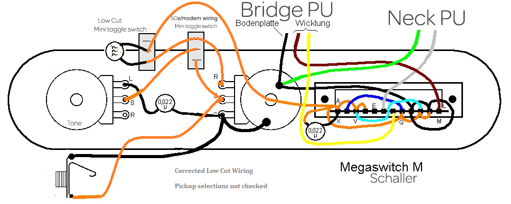
The 50's/Modern tone switch was correctly wired. It will have NO effect when both Volume and Tone are fully clockwise. When the Tone is fully clockwise and the Volume is reduced, you might notice a slightly brighter tone when the switch in in the '50s position. When the Volume and Tone are both less than fully clockwise, you'll notice a deeper tone cut when the switch is in the '50s position. This effect is even more obvious when the Tone is fully counter-clockwise and the Volume is below the middle of its rotation. |
|
abou
Rookie Solder Flinger

Posts: 9
Likes: 0
|
Post by abou on May 31, 2021 3:08:45 GMT -5
Hi !
Thank you everyone for your advices ! :-)
Yogi B, you get my attention on the separate black wire marked "Bodenplatte" on the scheme from the bridge PU. I didn't wired this cable, because I stupidly thought that the ground connection was made by the ashtray bridge plate. "Bodenplatte" is the plate of the PU and not the ashtray bridge of course ! I will try this first, and look at the other propositions after.
|
|
|
|
Post by Yogi B on May 31, 2021 4:49:29 GMT -5
The capacitor needs to be before the volume and tone controls to take advantage of the loading they provide. And what happens in '50s mode at maximum volume and with low cut switch engaged when the tone control is rolled down? Something like this: Actually, I hadn't read the above properly and was assuming that in your wiring the low cut cap was 'before' the loading of the tone control in the fifties configuration only, but I was mistaken. "The capacitor needs to be before the volume and tone controls to take advantage of the loading they it provides." okay, sure, but 'before' the tone control too? Then you end up with something similar to the wiring of Jaguar's 'strangle' cap in which the tone control is interactive with the bass cutoff frequency. I know people can live with that on a Jag, but it's probably worth avoiding if we can -- what's more is that with '50s wiring the amount of interactivity would be dependent on the setting of the volume control. That last part is unavoidable because the circuit positioning is transitive: ideally the low cut cap would be placed 'before' the volume control and 'after' the tone control, but '50s wiring mandates that the tone control follows the volume control -- both of those cannot be concurrently true. There's not a perfect solution, but the best is probably: (optional: modern wired tone) -> (optional: low cut cap) -> volume -> (optional: '50s wired tone) -> output
This way interactivity between the low cut and tone control is confined to only the '50s wiring mode. Either that, or just to have the cap (or likely a smaller valued one) directly at the output as previously shown and live with the fact this means that the low cut frequency is exclusively dependent on the input impedance of whatever you're plugging in to. Yogi B, you get my attention on the separate black wire marked "Bodenplatte" on the scheme from the bridge PU. I didn't wired this cable, because I stupidly thought that the ground connection was made by the ashtray bridge plate. That's not a stupid thought, if I'm correct it's part of the cause of your issue. The ashtray bridge is itself grounded and then via the screws (and springs) is grounding the bridge pickup's baseplate. This means that with the normal 2-wire pickup wiring one of the ends of the winding is also attached to ground via its connection the the baseplate, and the baseplate's connection to the ashtray bridge, etc. The problem comes when a wiring scheme needs that end of the winding to not be grounded (i.e. series or out-of-phase wirings). Technically the extra wire running to the bridge baseplate probably isn't needed, as you surmised it should already be grounded via the grounding of the ashtray bridge -- the third wire is mainly there just to be sure. (In other schemes where the neck pickup is the one being modified, the extra wire is more necessary owing to fact that neck pickup cover is unlikely to be grounded otherwise -- unless you had a metal scratchplate for example.) The more important part is the disconnection of the bridge pickup winding from the baseplate. |
|
abou
Rookie Solder Flinger

Posts: 9
Likes: 0
|
Post by abou on Jun 3, 2021 14:34:09 GMT -5
Hi ! Thanks for all your interesting informations ! I tried the wiring diagram posted bu reTrEaD, and add a wire from the baseplate of the bridge PU to the ground (indeed it's not usefull cause i confirm that the connection is made by the screws of the ashtray bridge). The result seems to be exactly the same than before. I did the multi-meter test and the screwdriver test, not have time yet to restring the guitar. Same value, and the toggle switches are not operating. Note that when I don't push the low cut switch, there is no value on the multi-meter. Yogi B, you said: "The more important part is the disconnection of the bridge pickup winding from the baseplate." I didn't know that, should I cut the little wire from the baseplate to the other plate ? it seems they are touching each other. 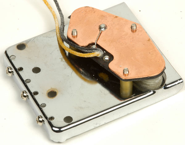 |
|
|
|
Post by ashcatlt on Jun 5, 2021 12:47:03 GMT -5
...should I cut the little wire from the baseplate to the other plate ? Yes! BUT then neither the baseplate nor (much more importantly) the bridge/strings will be grounded, so you'll need to find some way to connect another wire from the bridge to the the actual circuit ground. I'd probably just wrap it around the one of the screws. Maybe use a ring connector. You might try to attach a wire to the baseplate where that one already is, but I don't love trying to solder to big hunks of metal. |
|
abou
Rookie Solder Flinger

Posts: 9
Likes: 0
|
Post by abou on Jun 11, 2021 3:58:31 GMT -5
Hi,
I did this, and now I have these values:
1 bridge. 6,66
2 bridge and neck out of phase parallel ? 7,31. It's the same value that the neck PU alone, but the screwdriver test confirms both PU are ON
3 bridge and neck in phase parallel. 3,53
4 bridge and neck in phase in series. 13,57
5 neck. 7,31
Still doesn't stringed the instrument but it seems good, what do you think?
I did the screwdriver test, and it seems that the 2 toggle switches are still innefective.
|
|
Deleted
Deleted Member
Posts: 0
Likes:
|
Post by Deleted on Jun 11, 2021 4:16:17 GMT -5
1 bridge. 6,66
2 bridge and neck out of phase parallel ? 7,31. It's the same value that the neck PU alone, but the screwdriver test confirms both PU are ON
3 bridge and neck in phase parallel. 3,53
4 bridge and neck in phase in series. 13,57
5 neck. 7,31
So in phase or out of phase doesnt matter to the maths
Parallel it should be 1/((1/Neck)+(1/Bridge))
Series Neck+Bridge
6'660 Ohms i'm guessing (nice way to right this is 6K66) for the Bridge
and 7'310 (7K31) for the Neck
3485 for Parallel this will include any Switching and extra wire so looking around that figure 68 Ohms extra (in a pure world, could add on resistance with how much the probs are touching the testing points etc)
13'970 for Series
So yes No.2 position is missing the bridge some how.
I did think a "ScrewDriver Test" is slapping the Pickups to check they are working
The Toggle switches you should only notice they are working by stringing up and listening to the tone given off!
(i might be missing some thing here)
|
|
|
|
Post by Yogi B on Jun 12, 2021 15:49:52 GMT -5
2: bridge and neck out of phase parallel ? 7,31. It's the same value that the neck PU alone, but the screwdriver test confirms both PU are ON This is what I'd expect, yes. So in phase or out of phase doesn't matter to the maths Ah but, as I wrote in my previous reply, position 2 is actually parallel half-out-of-phase — there is a capacitor placed in series with the bridge pickup. Therefore a measurement of DC resistance will only "see" the resistance of the neck pickup (and volume control), because the impedance of a capacitor increases at lower frequencies, becoming effectively infinite at 0Hz DC. Still doesn't stringed the instrument but it seems good, what do you think? I did the screwdriver test, and it seems that the 2 toggle switches are still ineffective. Like @angellahash above, I don't think that you'll be able to hear the difference that the toggle switches provide without stringing up. |
|