cmscss
Meter Reader 1st Class
   Ad-free Angel
Posts: 78 
Likes: 2
|
Post by cmscss on Oct 25, 2020 23:17:01 GMT -5
Hi There, With previous help from you guys, I have a working guitar with out-of-phase and series/parallel DPDT toggles. However, I'd like to replace the toggles with momentary switches. Here's the momentary switch I have: www.digikey.com/en/products/detail/nkk-switches/LP0125CCKW01A/2105102What's a good methodology for working how to translate the lugs or wiring? After playing around with a multimeter, I think the top/bottom lugs on the momentary switch are equivalent to the middle lugs on the toggle? I say this because I don't get continuity unless one of the probes is on either the top or bottom lugs. Disclaimer: I can solder but have no clue about electronics sorry. Any help would be much appreciated. Cheers   |
|
|
|
Post by newey on Oct 26, 2020 6:52:56 GMT -5
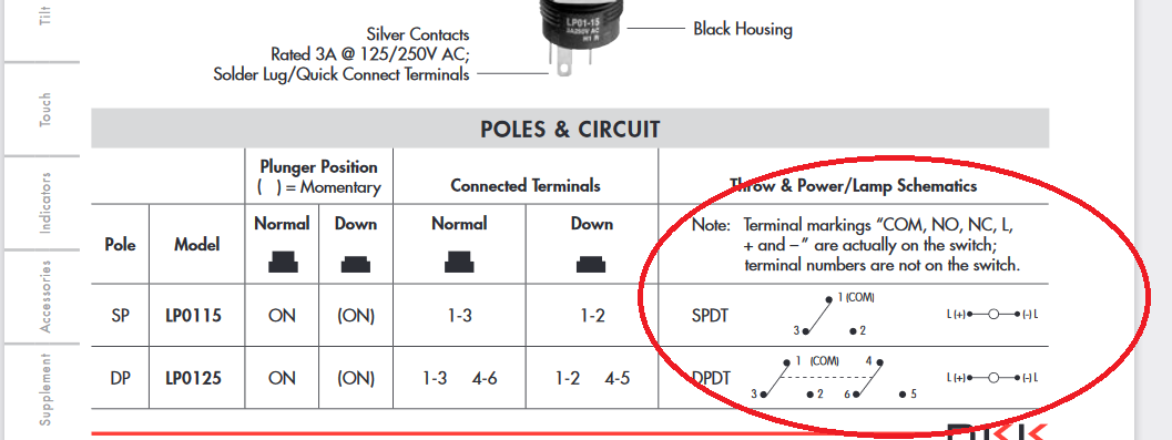
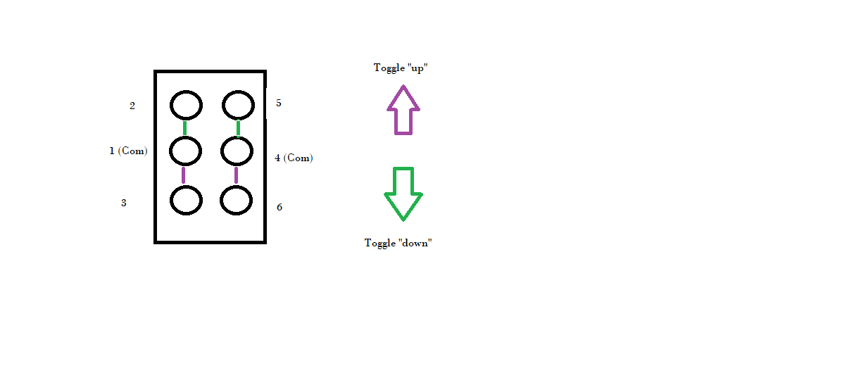
As I mentioned in the other thread, the momentary swicthes are labeled "C" for the common, "NO" for normally open, NC for normally closed. There are 2 poles, so 2 of each. (Also, some of these switches have LED illumination, you didn't say whether you bought that type or not. If you did, there will be 3 added lugs for the LED, labeled "L","+" and "-". If so, you can ignore these unless you also want the switch to light up, in which case a battery will need to be wired in) The switch data sheet from the manufacturer shows the info you need:  The DPDT toggle switches don't directly translate to the momentary switch, since they are not momentary. But if we number the lugs the same as the pushbutton momentaries, we get this:  Note that I have color-coded the internal switch connections for each position, so you can see "what connects to what". Also note that, just as with your momentaries, there is no connection between the 2 poles of the switch, unless you wire them togehter (as with your phase switch, for example). |
|
cmscss
Meter Reader 1st Class
   Ad-free Angel
Posts: 78 
Likes: 2
|
Post by cmscss on Oct 26, 2020 15:31:21 GMT -5
Thanks for the reply, I know this is simple for you guys so thanks for the patience. As I mentioned in the other thread, the momentary swicthes are labeled "C" for the common, "NO" for normally open, NC for normally closed. There are 2 poles, so 2 of each. OK, I can finally see markings with an LED torch and a magnifying glass but can't take a photo because they're not visible. However, I've drawn out what I see...  Also, some of these switches have LED illumination, you didn't say whether you bought that type or not. If you did, there will be 3 added lugs for the LED, labeled "L","+" and "-". If so, you can ignore these unless you also want the switch to light up, in which case a battery will need to be wired in. I don't see any LEDs and I'm sure I didn't buy LED versions. However, there are markings for L-+ moulded into the plastic but I only have 6 lugs total which are for the switch - right? So I reckon there are no LEDs. The DPDT toggle switches don't directly translate to the momentary switch, since they are not momentary. But if we number the lugs the same as the pushbutton momentaries, we get this:  OK so looking at the common lugs, I've taken a stab at numbering the lugs on the momentary - does this look right?  Also note that, just as with your momentaries, there is no connection between the 2 poles of the switch, unless you wire them togehter (as with your phase switch, for example). So I'd need to translate the jumpers from the previous switches - right? And once we agree on lug numbers, it will be easier to wire the kill with reversible toggle from the other thread - right? Thanks agin for your patience, much appreciated. |
|
|
|
Post by newey on Oct 27, 2020 5:54:13 GMT -5
Your numbering looks fine. Numbering the NO as 2 and 5, NC as 3 and 6 is arbitrary, it could just as easily be the other way around, but it won't matter for your purposes.
The "L" labelling on the body of the switch just reflects that the mfr uses the same outer casing for both LED and non-LED types. If yours was the LED type, there would be more terminals.
|
|
cmscss
Meter Reader 1st Class
   Ad-free Angel
Posts: 78 
Likes: 2
|
Post by cmscss on Oct 27, 2020 14:03:02 GMT -5
Your numbering looks fine. Numbering the NO as 2 and 5, NC as 3 and 6 is arbitrary, it could just as easily be the other way around, but it won't matter for your purposes. Ah, I think I know what you mean. I interpreted closed as off when in reality closing the circuit means on - is that right? So if we look at the numbering from the manufacturers diagram...  The numbering should be: NO = 3, 6 NC = 2, 5 Is that what you mean? |
|
|
|
Post by newey on Oct 27, 2020 14:52:32 GMT -5
The numbering should be: NO = 3, 6 NC = 2, 5 Is that what you mean? No, I meant that since the mfr. labels the lugs as NO or NC, but doesn't number them, it's completely arbitrary which way around we number them, so long as we do so consistently between the two poles (as per the schematic diagram above). But since you're only using 1/2 of the switch, it doesn't really matter which is which, and you answered any question in the other thread by checking the switch with a meter. |
|
cmscss
Meter Reader 1st Class
   Ad-free Angel
Posts: 78 
Likes: 2
|
Post by cmscss on Oct 28, 2020 0:37:30 GMT -5
OK, here's my translation from the previous wiring with the added reversible kill switch.  And for reference, here's the wiring for the toggles (which works) that the above momentary version was translated from.  |
|
|
|
Post by newey on Oct 28, 2020 5:31:36 GMT -5
Well, the kill switch is OK . . .  Understand how your momentary switches work. The "normal" state of the switch is with the button not being pushed in, the momentary state is with the button pushed. "Open" means no contact is being made, and "closed" means contact is being made to the common lug. So, if you wire to the "NO" lugs, those lugs are not connected to the commmon lug until the button is pushed to make the connection; wire to the NC lugs, and connection is always made until the button is pushed, breaking the connection to the commmon lug. Let's look at your phase switch. You have wired the pickup in phase to the NO lugs, and then crossed the connections to the NC lugs. This means that the pickup will always be OOP until you push the button- the NC lugs, the OOP state, is connected to the commons, pushing the button in switches to the NO lugs. This is just the opposite of what you want. To correct this, just move the pickup wires from the NO lugs to the NC lugs, leaving the red and green crossing wires as they are. Same problem with the phase switch. As shown, your pickups will always be in series, pushing the button puts them in parallel. So swap the NO and NC lugs. |
|
cmscss
Meter Reader 1st Class
   Ad-free Angel
Posts: 78 
Likes: 2
|
Post by cmscss on Oct 28, 2020 11:01:23 GMT -5
OK, thanks heaps for your help. So have swapped the NO and NC lugs and now have this... Also, does the kill toggle need to be grounded?  |
|
|
|
Post by newey on Oct 28, 2020 11:37:49 GMT -5
That should do it.
If you mean grounding the frame (i.e., exterior casing) of the switch, it probably won't make a bit of difference either way. Won't hurt to do so. In theory, a ground wire from the frame of the switch would eliminate any noise from the switch frame, but the tiny amount of metal in the frame is highly unlikely to contribute to any noise issues. But, you know, "never say never", as the saying goes. Personally, I never bother to run grounds from the switch frames.
|
|
cmscss
Meter Reader 1st Class
   Ad-free Angel
Posts: 78 
Likes: 2
|
Post by cmscss on Oct 28, 2020 11:49:53 GMT -5
OK awesome, will start to wire it up - and sorry in advance if I come back with questions!
Thanks for all your time and patience, very much appreciated.
|
|
cmscss
Meter Reader 1st Class
   Ad-free Angel
Posts: 78 
Likes: 2
|
Post by cmscss on Nov 2, 2020 11:14:43 GMT -5
OK, so I've wired it up and most of it works great thank you.
The only thing I've noticed is that when the pickup selector is in the neck position, the series/parallel switch doesn't seem to do anything. I'm wondering if somehow the neck position wiring is in series when in the neck position?
I've double checked everything and will have another look tomorrow to have a break from it but just thought I'd check to see if there's anything in the wiring that would cause this?
Cheers
|
|
|
|
Post by newey on Nov 2, 2020 11:46:38 GMT -5
The only thing I've noticed is that when the pickup selector is in the neck position, the series/parallel switch doesn't seem to do anything. I'm wondering if somehow the neck position wiring is in series when in the neck position? Yes, now that I look closer, that is an issue with the diagram. Since you are using the blue wire from the series/parallel switch to connect to the common lug on the lower pole of the switch, the blue wire is completing the series circuit via the red wires to lugs 2 and 3 on that pole of the 5-way. But lug #1 is disconnected on the second pole, so that you get the neck pickup only at that position. Since the bridge "hot" wire is the one being connected to make the series connection, it isn't connected in that position. Not sure I see a way around that, but let me look at this further, there may be a solution. |
|
cmscss
Meter Reader 1st Class
   Ad-free Angel
Posts: 78 
Likes: 2
|
Post by cmscss on Nov 20, 2020 14:42:47 GMT -5
Thanks for the reply, will have a good when I’m back at home. The previous wiring didn’t do this so will have a good look at your comments and compare that to the old wiring.
Cheers, Ben
|
|
cmscss
Meter Reader 1st Class
   Ad-free Angel
Posts: 78 
Likes: 2
|
Post by cmscss on Dec 14, 2020 12:53:25 GMT -5
Hi There, I've simplified things and remove the phase switch, and had a go at a wiring diagram. See what you think, any pointers would be much appreciated. Cheers  |
|