|
|
Post by frets on Mar 12, 2021 10:36:17 GMT -5
Happy Friday Guys,
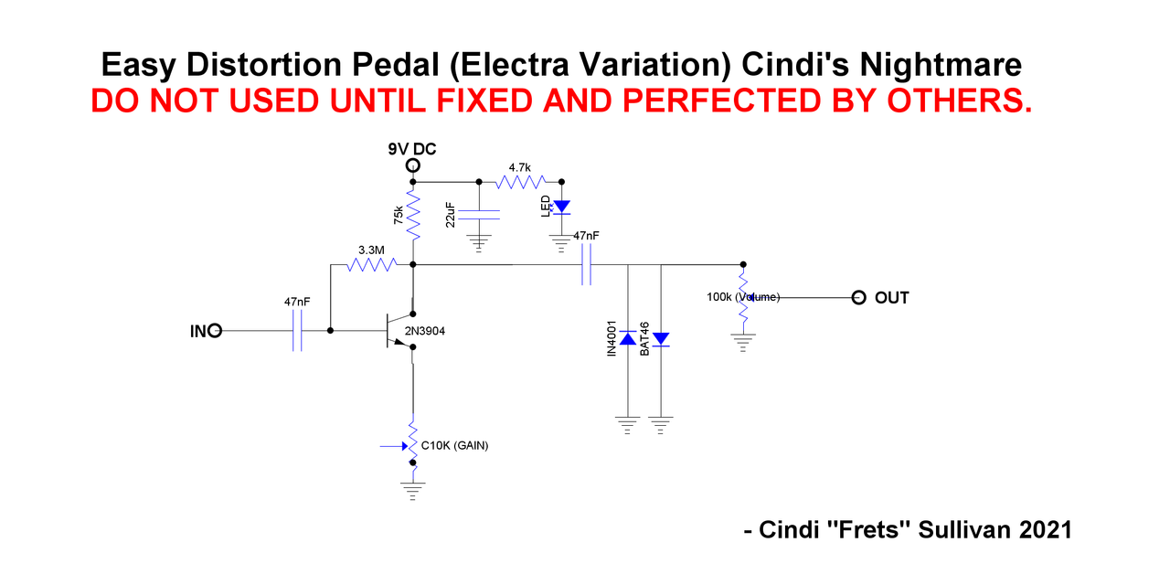
This post is about my derivation of a famous circuit for guitar effects.
Sometimes Trag and I talk about the Electra Overdrive which originated by Electra Guitars, a Japanese Axe Company that imported and sold their guitars with pluggable modules beginning 1976 (and ending around 1980). The Electra MPC (Modular Powered Circuits) Guitars had (has) two cartridge slots in the guitar body, where one plugs in a plastic encased cartridge, with control of the effect from the front of the guitar.
I first learned of these circuits when I bought one. The Overdrive/Distortion module was particularly good. The circuit is amazingly simple, and arguably, one is hard pressed to find a better sound than what comes out of this easy to build circuit. The circuit is easily available on the internet and has been tweaked by some but the diagrams are kinda incomplete.
In this post, I present my version of the circuit.
I have developed an onboard smd pcb that attaches to the face of a push pull that hosts my version of the Electra circuit. I am using it in some guitars I build. In the down position it is a tone pot, in the up position it is tone + my version of the Electra Overdrive/Distortion (mine is more of a Distortion). But anybody out there can build this extremely simple circuit and have a great distortion pedal. I call it “Cindi’s Nightmare”
NOTE: I’ll post the circuit once I fix my error. ☺️😜
|
|
|
|
Post by thetragichero on Mar 12, 2021 12:22:10 GMT -5
looks good, although i'm assuming the wiper of the gain pot should be attached to one of the outer lugs
|
|
|
|
Post by JohnH on Mar 12, 2021 13:50:57 GMT -5
looks good, although i'm assuming the wiper of the gain pot should be attached to one of the outer lugs Yes, its a neat little circuit. Id expect a cap from wiper to ground so it doesnt throw off the bias? Maybe I biggish one like 10uF for a full-range gain, or smaller like 100nF to boost mids and highs. |
|
|
|
Post by frets on Mar 12, 2021 13:57:29 GMT -5
Trag and John,
I have to use another circuit drawing program because I can get that wiper to the outside lug.
John,
Trag can correct me if I’m wrong but I believe the standard Electra circuit came with 100nF’s. I’ve been tweaking it for a while and think the 47nF sounds great with the diode pair. That said, maybe it’s just my preference.
I’m going to edit the post and take the diagram out. I would hate to think someone would build it with that mistake.
Oh, John your talking about the 100nF going from where to ground?
As you guys know, I’m not well versed with electrical symbol diagrams (they probably have a real name🙀!! I may draw it out as it looks in reality (if there is such a thing).
I’d like any help to make the circuit the best it can be. So recommendations please. Make Cindi’s Nightmare the most “Nightmarish.”
|
|
|
|
Post by frets on Mar 12, 2021 14:25:35 GMT -5
I’m putting it back up with its mistake and this disclaimer. DO NOT USE THIS DIAGRAM UNTIL IT IS FIXED AND PERFECTED! I’m not yelling, just warning.  Hopefully, I’ll have some more input on how to make it better (a relative construct). |
|
|
|
Post by JohnH on Mar 12, 2021 14:33:29 GMT -5
Im suggesting there should be a cap from the wiper of the 10k pot, to ground. This is instead of a wire link or no wire. As drawn, with the wiper not connected, the pot doesn't change anything The value of this cap needs to be experimented with so it sounds the best. The smaller it is, the more the added gain is just concentrated in high frequencies, a bigger cap will add more low-end thickness as well.
|
|
|
|
Post by thetragichero on Mar 12, 2021 16:37:19 GMT -5
if i remember correctly from breadboarding, an emitter bypass cap didn't do much so i left it off on mine (granted i used a fairly low ~100hfe germanium so i'm pretty sure that was limiting gain)
i do agree that that pot would have dc across it and likely be scratchy... an emitter resistor in parallel with a bypass cap with a pot (setup as a rheostat) in between the cap and ground could make an effective gain control and prevent dc across the pot (as the capacitor would block it). worth a try on the breadboard
|
|
|
|
Post by frets on Mar 14, 2021 13:57:42 GMT -5
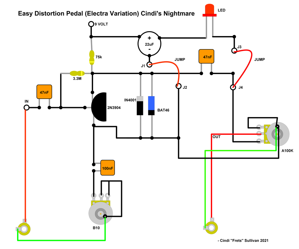
Hi Guys, I hope this version is correct. I made several changes. I added a 100nF going to the Gain pot, changed the Gain pot from a C10k to a B10k and added jacks. It could have a switch of one’s choice. The circuit is very good and I tested many diode combinations before discovering IN4001 and BAT46 together. I would appreciate any advice on components to make it fuller with an enhanced sustain.  |
|
|
|
Post by thetragichero on Mar 14, 2021 15:36:57 GMT -5
i suspect the gain pot won't provide any adjustment in this layout, but it should be very loud/saturated (actually, upon second look it might be very quiet/gated. regardless, not work as expected and likely burn up components while draining your power source). do you see what i see?
something else, although it's really a housekeeping thing: resistor from input to ground to give a path to ground for the input capacitor to drain to avoid/minimize switching pops. in a stomp box this is often 1M. if it is inside a guitar it might need to be a different value, i do not have experience with that and it may be dependent on the other specifics of the guitar wiring. lower value may roll off treble but that might not be a terrible thing if you're generating a bunch of harmonics anyway
i dig that this is a schematic with component pictures vs an actual layout. i can read schematics okay but often struggle reading layouts
|
|
|
|
Post by JohnH on Mar 14, 2021 16:32:11 GMT -5
I also much prefer to look at conventional schematic diagrams, particularly for active circuits like this. I learnt to read them 45 years ago! It's the best format for showing how something works, ahead of considering how it's built.
But, I follow what's going on. If your mini version has just a volume pot, then is the resistor from the transistor emitter to ground a fixed 10k? If so for more gain, just try with a cap in parallel with it, and try different cap values. If you find one that sounds promising but want it under pot control, then a cap in series with a pot (using an inner and and outer lug), all in parallel with the 10k. Ideally the pot would be something like a 50k reverse log (C type). Then gain will increase clockwise, with a nice spread.
It's important that from the transistor to ground there is a path through a 10k resistance, not going through a cap. Without this, it can't set up the right dc conditions so if can respond to inputs.
Id suggest a test on what you have too:
What is the dc power voltage to the circuit and what dc voltage can you read from ground to the collector? (top transistor connection on the diagrams). We'd like it to be somewhere around half the supply voltage so if can swing up and down from there, according to the signal.
|
|
|
|
Post by JohnH on Mar 14, 2021 16:47:14 GMT -5
This isn't a derail I hope! but I wanted to show a diagram with how we are talking about wiring up the gain pot with cap. The nearest I have to post is on my BludJuice drive. It's a jfet circuit, a different kind of critter to a normal transistor, but it has a similar gain control arrangement. Just look at R16, C2 and R1.  (BTW, that's a smokin' little tube-like drive circuit, it's in the effects schematics and diagrams sub-biard) |
|
|
|
Post by frets on Mar 14, 2021 17:01:30 GMT -5
So John, in mine it would come off the 2N3904 Ground to a 100nF and a 3.9k. The 3.9k would go immediately to ground. The 100nF to Lug 1. Lugs 2 & 3 go to ground. Would that be correct?
Thanks!!🥰
Thanks Trag, I’m trying to keep up. Still confused on the actual hookup of the gain pot;I.e., what goes to lug 1 etc. As you know electrical diagrams are difficult for me as is where to locate components; such as, the 1M.
Given mine is a tiny pcb board face plate on a push pull (you remember me talking about that last year, right?), I don’t have any gain setting. But I was trying to make my modified circuit amenable to an actual pedal. I still want to get this pedal right.
|
|
|
|
Post by JohnH on Mar 14, 2021 17:11:51 GMT -5
it's so hard to describe circuits in words. I think we can only use diagrams to be sure of understanding. I'm happy to have a go in a day or two.
|
|
|
|
Post by thetragichero on Mar 14, 2021 18:36:08 GMT -5
i will not try to be mysterious any longer: schematic as drawn grounds the emitter, which will generally produce GOBS of gain, but then there's also diodes to ground from the collector (without a dc-blocking cap in between) so basically all dc voltage above one diode drop (to lazy to look up the particular Vf) gets shunted to ground so it's an extreme dead battery fuzz (and the battery will die, maybe explode. maybe will provide enough current to blow the diode and then it'll go very loud)
|
|
|
|
Post by frets on Mar 15, 2021 11:13:05 GMT -5
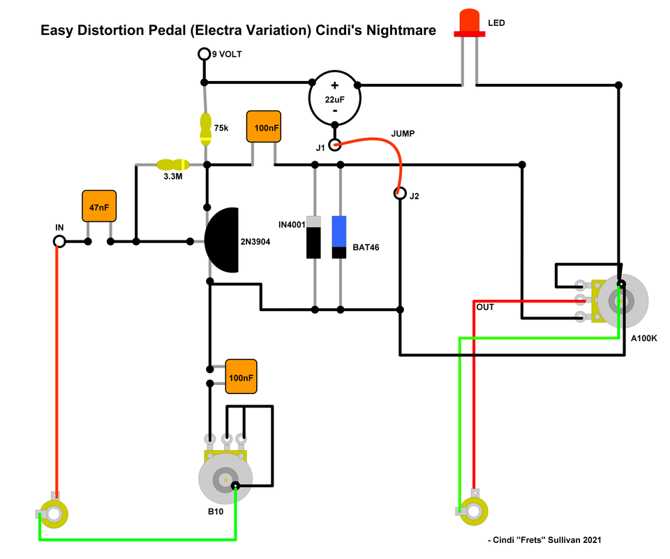
Trag, You weren’t being mysterious at all, I just didn’t understand it until it dawned on me this morning. I had the cap in the wrong place and have moved it in front of the diodes and bumped it up to 100nF. Still uncertain if I have that gain pot right.  |
|
|
|
Post by ashcatlt on Mar 15, 2021 12:41:57 GMT -5
Still uncertain if I have that gain pot right. I am fairly certain you have not. If there is an implied connection between the jack grounds, then that whole structure is just shorted and does nothing. There is no such connection drawn, and if it’s not there, IDK for sure what happens but I’m pretty sure it won’t be what you want. I think it just ends up increasing the hum, but... Edit - move the ground wire from between the transistor and cap to the grounded lug of the gain pot or its case or whatever. Edit again - I think you will want some resistor parallel to the whole gain pot/cap, literally from the transistor to ground. Without it I think DC gain is going to be infinite in one direction or another, which slams the whole thing into one of the rails and holds it there hard so that none of the wiggles that you actually want can come through. |
|
|
|
Post by thetragichero on Mar 15, 2021 12:53:16 GMT -5
i hacked up yer purty drawing in gimp  choose Rb based on where you want the transistor biased, worth try on the breadboard to see what you like. emitter bypass cap really is determined by the emitter resistor value, although 1-4.7uf is a ballpark value that will boost fewer bass frequencies and sound "tighter" (here's where you see what the corner frequency would be www.muzique.com/schem/filter.htm)i left the link to ground on the emitter and circled it, so you can see why you'd want it removed 1M resistor to ground should help reduce pops while switching and as ash pointed out, it's good practice to show that both the input and output jack sleeves are connected to ground. this is generally implied in a metal stompbox enclosure (heck, boss often doesn't solder wires to jack sleeves, relying on physical connection to the metal enclosure... bad practice in my opinion because we live in an imperfect world and screws come loose) |
|
|
|
Post by frets on Mar 15, 2021 13:00:22 GMT -5
Trag,
Bless you!!🥰
Thank you so much. It’s actually starting to make sense to me. That’s a scary thought.
Thanks to John and Ash too!
|
|
|
|
Post by frets on Mar 15, 2021 16:35:28 GMT -5
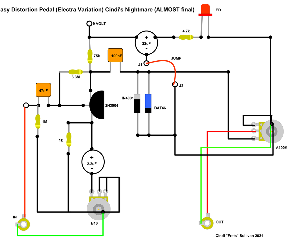
I know you guys are sick and tired of seeing this thing, but I’m bound to get it perfect. Added 2.2uF and a 1k for a corner frequency of 72.34. Add a 4.7k prior to the LED. It sounds pretty good to me. I like it. But if one of you see something glaringly wrong, I would appreciate it. I consider this the final version unless I have more input. You’re all thinking “thank God!!”  |
|
|
|
Post by thetragichero on Mar 15, 2021 18:07:27 GMT -5
now you're cookin'!
|
|