|
|
Post by soundengine on Mar 21, 2021 18:09:46 GMT -5
Hello everyone, first post here.
You have to believe me, I searched the internet high and low and couldn’t find an exact situation like this, but have found a few similar situations.
So, what I have is this Gibson SGZ that I am rebuilding. The guitar originally came with a Single conductor stacked 490r Humbucker at the neck and a single conductor traditional 498t humbucker at the bridge. One tone, one volume and a 3 way switch.
What I would like to do is keep the single conductor stacked humbucker and throw in a 4 conductor dirty fingers pickup I have laying around for the bridge position. I would loooove to make the dirty fingers push/pull coil split, but I’ll be honest,
I’m at a loss for how to wire this with a single conductor neck pickup and only having one volume and one tone.
I’m not shy with soldering, I do it all the time, but from a guitar electronics mechanical point of view, I would like to find some guidance instead of futzing around with it for too long.
Any help is appreciated. Thank you!
|
|
|
|
Post by newey on Mar 21, 2021 22:17:03 GMT -5
soundengine-
Hello and Welcome to GNutz2!
When you say the neck HB is "single conductor", is it one insulated wire surrounded by a braided shield?
If so, no real issues wiring in a new HB at the bridge. I don't know how this guitar is wired, but with master V and T controls, typically the pickups would be wired to the 3-way switch first, and then from there to the V and T pots. If that's how yours is, then the neck HB wiring doesn't have to change at all. It gets wired to the 3-way switch just as it is now. All the wiring for the new 4-wire bridge HB will take place "upstream", on the pickup side of the 3-way switch. If you want to add a coli split switch for the bridge, that can be easily done with a push/pull pot.
|
|
|
|
Post by JohnH on Mar 21, 2021 23:31:38 GMT -5
A watchit: Can a push-pull pot actually fit in the skinny cavity of an SG?
|
|
|
|
Post by soundengine on Mar 22, 2021 7:43:49 GMT -5
soundengine- Hello and Welcome to GNutz2!When you say the neck HB is "single conductor", is it one insulated wire surrounded by a braided shield? If so, no real issues wiring in a new HB at the bridge. I don't know how this guitar is wired, but with master V and T controls, typically the pickups would be wired to the 3-way switch first, and then from there to the V and T pots. If that's how yours is, then the neck HB wiring doesn't have to change at all. It gets wired to the 3-way switch just as it is now. All the wiring for the new 4-wire bridge HB will take place "upstream", on the pickup side of the 3-way switch. If you want to add a coli split switch for the bridge, that can be easily done with a push/pull pot. Thanks for the reply. Yes - it’s a insulated cable with the braided shielding. Sorry for the confusion. As far as originally wired - that I don’t know as the ORIGINAL wiring from 1995 was ripped out and converted to something ugly and not original sometime in the past 25 years, I ripped it all out recently for a paint job, and now I’m getting into the rewriting of it. JohnH - I assume so. My SG Modern has Push/Pull pots. Don’t know if they are special or not. 😬 |
|
|
|
Post by newey on Mar 22, 2021 8:07:33 GMT -5
So, do you need a diagram?
|
|
|
|
Post by soundengine on Mar 22, 2021 22:26:32 GMT -5
So, do you need a diagram? I would gladly except one and be most appreciative of it, but I certainly wouldn’t want anyone to go out of their way for it if they didn’t feel like it. 😁 |
|
|
|
Post by newey on Mar 23, 2021 5:34:54 GMT -5
Our preference is for folks to try their own hand at a diagram, which one or more of us here can then double-check. From personal experience, I can say that working out my own wiring diagrams made the actual wiring process much easier, simply by knowing how the scheme was supposed to work rather than simply blindly following someone else's diagram.
But we'll be happy to draw something up if a member needs a more "paint-by-numbers" approach. It will probably be a few days however.
|
|
|
|
Post by soundengine on Mar 23, 2021 8:52:19 GMT -5
Our preference is for folks to try their own hand at a diagram, which one or more of us here can then double-check. From personal experience, I can say that working out my own wiring diagrams made the actual wiring process much easier, simply by knowing how the scheme was supposed to work rather than simply blindly following someone else's diagram. But we'll be happy to draw something up if a member needs a more "paint-by-numbers" approach. It will probably be a few days however. Yeah, let me have a stab at it when I can wrap my head around it a bit more(this weekend perhaps), and I’ll check back in and see if I get a passing grade. Thanks for the help! |
|
syddd
Meter Reader 1st Class
  
Posts: 62 
Likes: 10
|
Post by syddd on Mar 25, 2021 1:38:52 GMT -5
Unless it's a CTS style push-pull where the switch lugs are mounted on the side of the pot then I have to echo John's concerns around whether a standard Alpha/Bourns push pull pot will actually fit.
|
|
|
|
Post by JohnH on Mar 25, 2021 7:46:08 GMT -5
Since this thread I've read of a few SG push-pull installations. I guess it'll come down to some careful measurements and buying pots that come with dimensional specs.
|
|
|
|
Post by ashcatlt on Mar 25, 2021 11:25:22 GMT -5
This has to exist somewhere. Probably here. It’s like the third simplest wiring arrangement and the simplest mod and neither of them really depend on the other, but I have to believe it’s been done as a whole diagram at least 1800 times. It might be labeled for an SC and an HB, but it’ll work fine.
|
|
|
|
Post by newey on Mar 25, 2021 11:41:06 GMT -5
I have to believe it’s been done as a whole diagram at least 1800 times. 1801, by my count.  . Yeah, we can probably find a diagram to point him towards. |
|
|
|
Post by frets on Mar 25, 2021 15:22:14 GMT -5
I did this super fast. You can swap the cap on the other side of the pot if you prefer that roll.  |
|
|
|
Post by frets on Mar 25, 2021 15:27:06 GMT -5
Oops, you want the push pull coil split. I’ll be back.
|
|
|
|
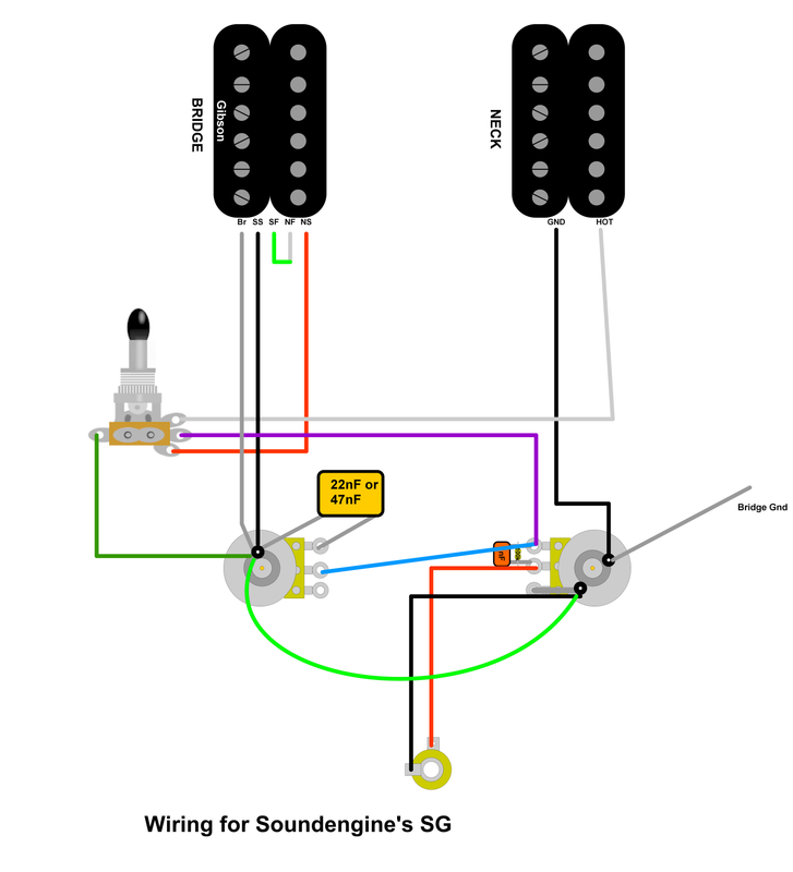
Post by frets on Mar 25, 2021 17:56:52 GMT -5
|
|
|
|
Post by newey on Mar 25, 2021 18:34:47 GMT -5
frets- Your diagram looks correct, including proper Gibson colors. The only comment I would make is that, where the grounding lug at the rear of the P/P switch is shown, that lug needs to be grounded for the coil split to work (as well as based upon general principles). The diagram is a bit ambiguous as to whether the black wire from the neck pickup just crosses over the switch at that point, or whether it is meant to be connected to the lug, and hence to the jack sleeve. soundengine- frets has your back.
|
|
|
|
Post by frets on Mar 26, 2021 11:43:41 GMT -5
Oops, thanks Newey, I did the diagram too quickly, I will fix it and post it when I get a little time here. Thanks!!
|
|
|
|
Post by soundengine on Mar 28, 2021 21:41:03 GMT -5
Oops, thanks Newey, I did the diagram too quickly, I will fix it and post it when I get a little time here. Thanks!! Wow! Thanks for that. I’ll admit I got tied up this weekend and wasn’t able to mess around with it. The guitar is getting a new paint job as the old Gibson SGZ “Platinum” color(more of a ugly green-grey) reeked of 20 years of someone else’s cigarette smoke. This def helps! Now I’m just lining up my ducks to get this thing rebuilt when it gets back from the paint shop. Cheers! |
|
|
|
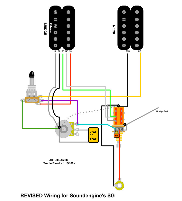
Post by frets on Mar 30, 2021 11:55:38 GMT -5
Updated  |
|
|
|
Post by newey on Mar 30, 2021 17:17:00 GMT -5
Poi-fect!  |
|
|
|
Post by soundengine on Apr 2, 2021 16:15:19 GMT -5
Poi-fect!  Thank you so much! |
|
|
|
Post by soundengine on Apr 2, 2021 16:15:43 GMT -5
Updated  Thank you so much! |
|