|
|
Post by stratotarts on Mar 27, 2021 12:36:38 GMT -5
The demand for test coils increased enough to make it important for me to refine the assembly techniques a bit. I realized that it was an opportunity to document it for anyone who wants to build one themselves. I was going to attach the document but it seems not to work for some reason. So I will just post a link to the file:
|
|
|
|
Post by antigua on Mar 27, 2021 23:05:22 GMT -5
That's a neat looking induction coil. I see you wind 50 turns according to the caption in one of the pics. I've found that if I add more turns, I get bet a better S/N ratio because the inducing coil will put out a stronger magnetic field. Since it's only necessary to have a inducer whose own resonant peak is a lot higher than the pickup, could you put, say five hundred turns of 42 AWG, or whatever will fit, onto the test coil in order to get a strong induction and better S/N ratio?
I haven't experimented with these larger coils since having been using the popsicle stick inductor coils, and in that case I'm limited by the tiny geometry.
|
|
|
|
Post by stratotarts on Mar 29, 2021 22:35:56 GMT -5
More on the wind count later, but I am now building exciters based on off the shelf potted inductors such as this one:
I can buy these components inexpensively at the local electronics store. There is a 100 ohm resistor in series under the shrink wrap tubing. The ruler shows centimeters.
|
|
|
|
Post by antigua on Mar 29, 2021 23:58:26 GMT -5
More on the wind count later, but I am now building exciters based on off the shelf potted inductors such as this one:
I can buy these components inexpensively at the local electronics store. There is a 100 ohm resistor in series under the shrink wrap tubing. The ruler shows centimeters.
Isn't there a risk that the potted inductor's permeability will interfere with the measurement? |
|
|
|
Post by newey on Mar 30, 2021 6:14:26 GMT -5
I was going to attach the document but it seems not to work for some reason. So I will just post a link to the file: FYI- We have disabled the attachment feature for the Board here, as ProBoards has a bandwidth limit above which they want to charge us. We kept hitting the limit as people would attach long strings of photos of their projects. While you can't use the attachment feature, you can convert it to an image and post it using the image posting tools, assuming it's not multiple pages. |
|
|
|
Post by stratotarts on Mar 30, 2021 9:26:36 GMT -5
Isn't there a risk that the potted inductor's permeability will interfere with the measurement? Generally, there could be, since inductors are constructed with different core materials. But this type uses a ferrite core, which has an exceedingly high permeability and so is effectively transparent as far as the measurement is concerned. I also A/B tested it with a full sized air-core test coil using the same pickup. The alignment of results was almost perfect, I can't find the plots right now because of all the PC swapping around I had to do recently. As I recall, as near perfect as two consecutive plots using the same test coil. |
|
|
|
Post by ms on Apr 2, 2021 13:04:51 GMT -5
Isn't there a risk that the potted inductor's permeability will interfere with the measurement? Generally, there could be, since inductors are constructed with different core materials. But this type uses a ferrite core, which has an exceedingly high permeability and so is effectively transparent as far as the measurement is concerned. I also A/B tested it with a full sized air-core test coil using the same pickup. The alignment of results was almost perfect, I can't find the plots right now because of all the PC swapping around I had to do recently. As I recall, as near perfect as two consecutive plots using the same test coil. The image shows that a very small ferrite core exciter coil has a small effect on the pickup impedance. The top left shows the test pickup and the driver coil. When placed on a pole piece, the coil becomes magnetized, and thus tends to stay in place. The coil has three turns and is apparently under 1 micro Henry in inductance. It is driven from the headphone jack of an element 24. I integrate for a minute or so to get adequate signal to noise ratio. A response measurement is shown to the right. The test wave form is a pair of complementary codes, together containing all relevant frequencies nearly uniformly. The processing uses a cross spectral technique and the output is a ratio in which any frequency variations in the spectrum of the test waveform are removed. The instrument input of the element 24 has a high enough capacitance to lower the inherent resonant frequency a lot. I did not use a low capacitance buffer for this measurement. The lower two plots show the pickup impedance without and with the driver coil in place. There is a small effect on the inductance and resonant frequency. The frequency measurement is very accurate since there is no significant loading effect. I think that a larger piece of ferrite would have a larger effect on the pickup. 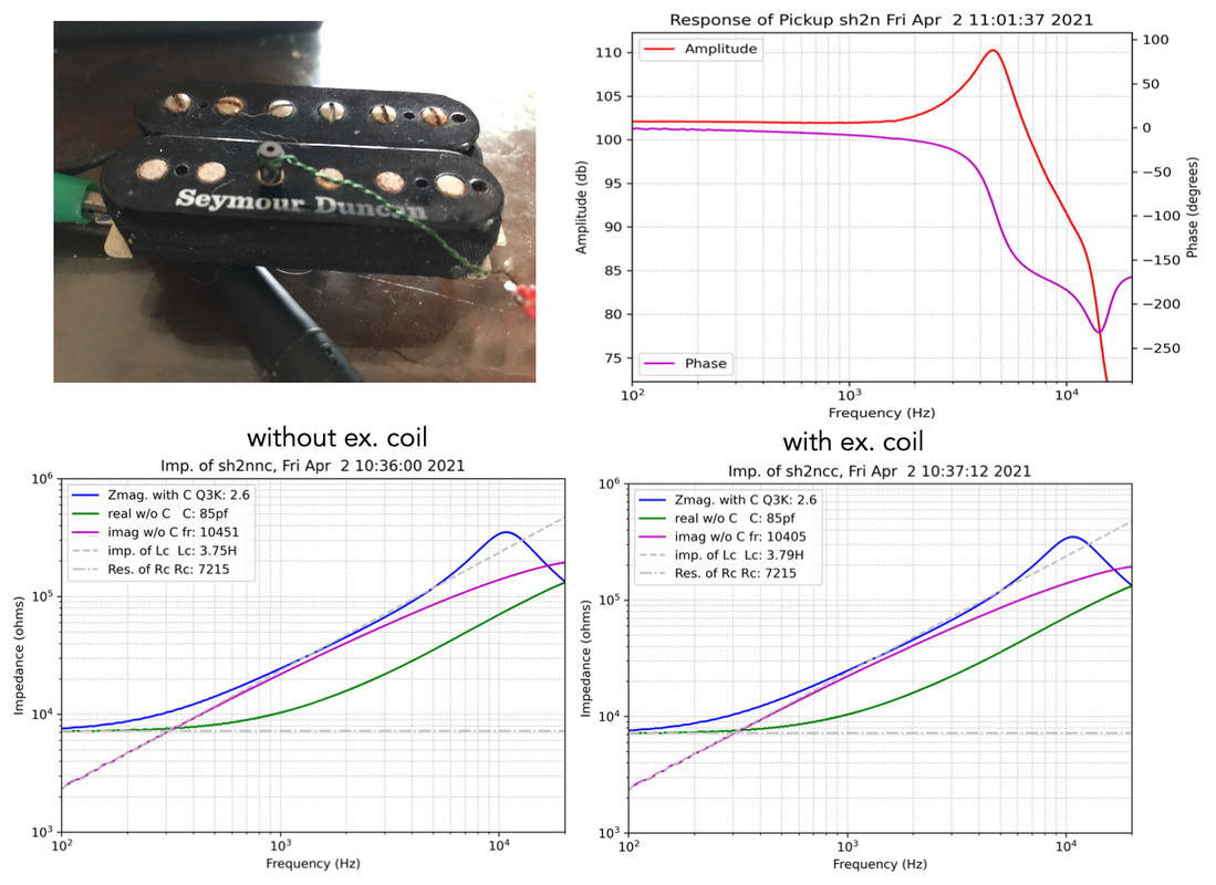 |
|
|
|
Post by stratotarts on May 1, 2021 20:30:56 GMT -5
Another thing about the stock inductors - I haven't cracked one open yet, but it's likely to have a bit of potting and case plastic between the outside surface and the inductor core. That should help isolate it magnetically also. I bought some smaller inductors to test, but I've been swamped and haven't had time. I did get a chance to measure my "standard coil" - 50 turns on a humbucker bobbin. I came up with 105 uH and 24nF, which if I'm not mistaken would make it resonate around 32 kHz. I'm also too swamped to test that directly. If that is the case, I would consider it too close to the upper end of the audio test range to increase the number of turns very much. That is with AWG#30 wire, I previously used #26 and I didn't have a chance to measure that. But it's probably not far off. At the moment there is plenty of headroom for testing, I usually use the low gain setting on the integrator and if I need more, I can just flip the switch and add 20dB.
|
|


