|
|
Post by newey on Mar 29, 2021 22:06:26 GMT -5
So, as I await a new pickup for my Esquire-ish guitar. I've been thinking a rewiring is in order. Currently, it has a std. 3-way lever switch wired somewhat similar to the original Esquire wiring- One position gives the pickup with the V and T controls, another gives a direct out setting, bypassing the V and T pots, and the third has a cap in parallel for a treble cut setting, the "tone at 0" thing. So, I'm thinking of replacing the 3-way with a 5-way, non-superswitch. (Although I may have to opt for the half-Superswitch if no one comes through on this challenge.) I sat down with pen and papaer tonight but was unable to come up with something that covered all the bases. So I'm throwing down the gaunlet, so to speak. Here's the challenge: - One single coil Tele pickup at the bridge position, a la the famous Esquire.
- One regular 5-way lever switch (not a Superswitch)
- No redundant settings on the switch and no silent/off settings
- One setting to be direct out, bypassing V and T pots
- One setting with a cap in parallel with the pickup
- One setting with a (different) cap in series with the pickup
- At least one setting that utilizes std V and T pots
Optional ideas that might be incorporated: One setting might bypass the tone pot only, leaving the V pot in circuit. Another setting might give a cap in series and a cap in parallel both. So, can anyone come up with a scheme for one single coil pickup and a 5-way switch that does all of the above (or at least most of it?). Note- the only prize for coming up with such a scheme is my eternal gratitude and some bragging rights. But I note that we are coming up on our anniversary next month, so this may be only the first of several challenges.  |
|
|
|
Post by frets on Mar 30, 2021 0:31:56 GMT -5
Yogi will win this one 😺
|
|
|
|
Post by JohnH on Mar 30, 2021 1:13:53 GMT -5
looks like one more target may be needed to make the wish list of 5. How about
a very small cap in parallel? lowers the peak frequency from single into p90 or Hb range.
|
|
|
|
Post by newey on Mar 30, 2021 5:45:43 GMT -5
How about a very small cap in parallel? lowers the peak frequency from single into p90 or Hb range. Sounds good. The positions can be flexible so long as the "wish list" gets fulfilled! Also my first thought. He is, after all, smarter than the average bear . . . |
|
|
|
Post by JohnH on Mar 30, 2021 7:27:05 GMT -5
Here's one. Its worth no more than an E- since it fails to use a standard 5 way. But it works with a half superswitch, ie, a full 2P5T Top to bottom: full bypaass full bypass with series cap full bypass with small cap in parallel full bypass with with big cap in parallel V+T normal  (diagram edited 31/3/21) |
|
|
|
Post by newey on Mar 30, 2021 8:52:37 GMT -5
Yeah, I hadn't actually drawn a diagram but I just mentally figured that a half Superswitch would do it for sure. If no one comes up with a std 5-way version, I may have to spring for the half Superswitch.
|
|
|
|
Post by JohnH on Mar 30, 2021 15:59:09 GMT -5
I made an edit to my diagram to make the grounding better, same principles though.
Without any further inspirations, it needed the two poles to properly switch the V and T pots in and out, and since the three options with added caps also use those poles, they are provided as bypassed options with no V and T, plus the full bypass.
I think it's a good range to get out of one pickup. Using a half superswitch, the order of options is a free choice. But I'm not seeing how to implement all that with a standard switch, particularly for whatever choices are intended for the 2 and 4 positions. Therefore I think some other concept needs to be used to get 5 good settings on a standard switch.
|
|
|
|
Post by newey on Mar 31, 2021 21:44:16 GMT -5
(Cue the muted trombone: "Waah waah waah waaaa. . . )
Yeah, if it can't be done with a regular 5-way switch, then I'm off to find a halfsie Superswitch. And to figure out a better challenge . . .
|
|
|
|
Post by newey on Oct 16, 2021 17:50:06 GMT -5
Ready to move forward with this project, so hopefully this diagram correctly implements JohnH 's schematic above. 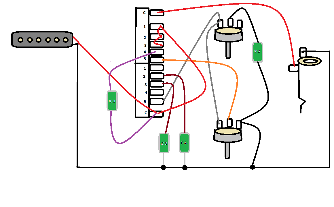 I think this could be a winner for one SC pickup, although I feel like the V and T controls should also be active at one of the parallel cap settings, 2 or 3. Or maybe just the V control, with the cap as the fixed tone. |
|
Deleted
Deleted Member
Posts: 0
Likes:
|
Post by Deleted on Oct 19, 2021 3:16:18 GMT -5
I always like to see the max i can get in to a circuit and feel POTS are wasted as they have more than a single use.
Dual Pot, top is the normal Resister and under it is a variable capacitor (ok a cheat one)
as you only use the Treble and Volume once in stage 5, the second wafer could be use to replace C3 & C4 under the Volume say and C2 under the Treble.
Giving you more of a range.
|
|
|
|
Post by Jaga on Oct 19, 2021 3:46:01 GMT -5
@angellahash, do you have a schematics explaining this idea?
|
|
|
|
Post by reTrEaD on Oct 19, 2021 9:38:42 GMT -5
I think this could be a winner for one SC pickup, although I feel like the V and T controls should also be active at one of the parallel cap settings, 2 or 3. Or maybe just the V control, with the cap as the fixed tone. It would be possible to add a cap in series with the V and T controls (either before or after them) in one or more positions. You could even add that series cap and have just the tone control (with the volume control loading the circuit but always full volume). But I don't see a way of ever using the volume control independent of the tone control. Or using the V and T with a parallel cap unless that parallel cap is always in the circuit. John's schematic rather than a wiring diagram, does a better job as an aid to visualize why this is so. It's necessary to use one pole of the switch feed the input to the V and T and the other to connect the output of the V and T to the output jack. There is no pole available to connect a cap to ground. You could use a dual-gang pot for the volume and use the other section with a parallel cap and select that network in the same manner as the regular volume and tone is being selected in the last position of the switch. But that can't be done with a regular pot. |
|
Deleted
Deleted Member
Posts: 0
Likes:
|
Post by Deleted on Oct 20, 2021 2:23:02 GMT -5
@angellahash, do you have a schematics explaining this idea? Yes why not.. I'll post it here (at work at the moment) |
|
|
|
Post by Yogi B on Oct 20, 2021 5:30:12 GMT -5
You could use a dual-gang pot for the volume and use the other section with a parallel cap and select that network in the same manner as the regular volume and tone is being selected in the last position of the switch. The logical extension to this idea being a quad-gang pot (or two dual-gangs, or even four individual pots — depending on how much independent control you wanted) for volume control in all positions except direct out. |
|
|
|
Post by newey on Oct 20, 2021 7:31:14 GMT -5
You could use a dual-gang pot for the volume and use the other section with a parallel cap and select that network in the same manner as the regular volume and tone is being selected in the last position of the switch. But that can't be done with a regular pot. I like the idea, but I'm already anticipating fitment problems into a Tele control cavity. I have some dual-gang pots in the parts bin, so I'll have to test fit everything and see. |
|
|
|
Post by jhng on Oct 21, 2021 15:17:27 GMT -5
Hello. I used to contribute here about 15 years ago and was just rummaging around to see if I had left a copy of a particular wiring diagram. I saw newey's challenge above and couldn't resist having a go while on the train. Presuming it works, I came up with a solution using the traditional five-way switch. Sharing it below just in case it is helpful (and hoping that I have understood image posting properly). 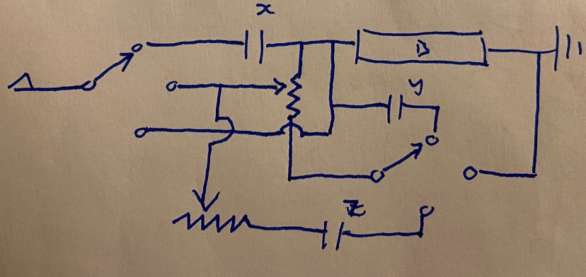 The wiring gives the following options (again, presuming I've got it right): 1. Bridge in series with cap x 2. Bridge in parallel with cap y, plus Volume (and an unintended treble bleed on the Vol from cap x) 2. Bridge plus Volume (no cap or tone) 3. Bridge plus Volume and Tone (using cap z) 4. Bridge direct It's not the cleanest solution and involves pots and caps hanging from hot, but it should still work okay. Hope it is useful. Incidentally, although I was chuffed to see a number of my old mods still here (and on the surviving copy of the GN1 site) no sign of the wiring for my own actual guitar. I did it many years ago but it's developed an intermittent fault in one position, so I'm going to have delve in again. I'm hoping I stashed a copy of the wiring in the cavity, otherwise it's back to first principles... |
|
|
|
Post by reTrEaD on Oct 21, 2021 16:15:10 GMT -5
Hi Hastings! Good to see you posting again.  If you have time, edit your post. Your sequence has two #2s. I'm sure most everyone will understand what you meant, though. Unused caps and pots hanging is less of an issue than a hanging coil. And even with hanging coils, the mindset is: Avoid it when possible, but it's not a deal-breaker. I haven't fully vetted your diagram but being able to accomplish the goals with a standard 5-way is impressive! However this one issue seems troubling: 2. Bridge in parallel with cap y, plus Volume (and an unintended treble bleed on the Vol from cap x) Cap-only treble bleeds aren't good. The cure is worse than the disease when the volume is at moderately low settings. I'd suggest trying a cap and resistor parallel combination that would be suitable as a TB instead of just a cap for 'X'. If that produces a useful tone in position 1, this might be a winner. |
|
|
|
Post by newey on Oct 21, 2021 18:18:11 GMT -5
jhng- Your schematic traces out fine by me. Good to hear from you again, and thanks much for doing the design. I, too, think it is a winner- and that makes you the winner of the wiring challenge. . . which gets you bragging rights, anyway.  I'll try to translate the schematic into a wiring diagram for reference. Do you mean that you can't find the thread you authored about it, or that you located the thread but the diagram or schematic has gone to parts unknown? If you know the thread, we may be able to help resurrect the image.
|
|
|
|
Post by Yogi B on Oct 21, 2021 20:12:27 GMT -5
jhng, reTrEaD, newey: it's not really a winner I'm afraid — I had almost identical (if not exactly the same) mistakes drawn up a few days ago, before deciding my best solution would be throwing more pots at the problem. reTrEaD, although treble bleeds and (capacitive) bass cuts are intrinsically quite similar in terms of component layout, the circuits are tuned quite differently via choices of component value (as you impressed upon ashcatlt quite recently). In order that the cap X doesn't begin cutting at too high a frequency in position #1 it must must be sufficiently large, however for treble bleed purposes it must be sufficiently small such that the volume control does not effectively become a bass cut control. Adding a parallel resistor would help balance out a larger cap in treble bleed situation, but to be effective for that purpose it would greatly hinder the amplitude bass cut achieved in position #1. And the above is the 'good news', on to position #4 ("Bridge plus Volume and Tone (using cap z)", labelled "3" at the time of writing). Here — due to the second notch position of the Strat switch connecting to both the centre and lower terminals (as drawn) — the "upper half" of the volume pot is shorted, similarly to how it is bypassed by cap X in the first notch position. This means you only have the lower half of the volume pot acting upon the circuit only as a variable load, not really a volume control. Although I, myself, have recently defended Phostenix's use of this type of circuit to achieve a no-load 'volume' type control, in general it isn't something I'd advocate — especially when it appears just a single switch position over from the properly functioning volume control that occurs in the centre position of this scheme.
|
|
|
|
Post by jhng on Oct 22, 2021 3:37:55 GMT -5
Here — due to the second notch position of the Strat switch connecting to both the centre and lower terminals (as drawn) — the "upper half" of the volume pot is shorted So it is. Hadn't spotted that. I'm very rusty at this sort of thing. newey, thank you for the kind suggestion. But I've looked over my posts from the era and I don't think I actually posted the schematic. Because it was bespoke for my own guitar rather than generally applicable I must have kept it to myself. Anyway, if I do need to do a fresh wiring, I will come by GN2 and share it. Very pleased to see that the forum is still thriving. |
|
|
|
Post by newey on Oct 22, 2021 6:00:32 GMT -5
on to position #4 ("Bridge plus Volume and Tone (using cap z)", labelled "3" at the time of writing). Here — due to the second notch position of the Strat switch connecting to both the centre and lower terminals (as drawn) — the "upper half" of the volume pot is shorted, similarly to how it is bypassed by cap X in the first notch position. Yeah, I see that now as well. Yogi B- Your suggestion of a dual-gang pot might eliminate this? Just kind of thinking out loud here, but if we re-ordered the positions such that one gang was at position one for Vol alone, one gang with the tone at the opposite end, with the direct out in the middle? In any event, it looks like jhng 's scheme will work, albeit with a wonky volume pot at position 4 (3 as labeled). I could probably live with that, the tone would still be different without the tone pot at the one position, and with the tone at the other. But this is all pretty much a theoretical exercise, as I already bought the half-Superswitch thinking the regular 5-way was a non-starter, per JohnH 's posts above. |
|
|
|
Post by Yogi B on Oct 22, 2021 14:55:10 GMT -5
Yogi B- Your suggestion of a dual-gang pot might eliminate this? That was reTrEaD's idea, I was just in favour of doubling down on it. (If it were me I'd prefer consistency offered by four gangs, either combined in the form of every non-direct position sharing the same 4-gang volume pot, or separately with each of the remaining four positions getting their own pot.) That wouldn't really help — to avoid the "wonky" volumes you'd need a switch that never connected to multiple 'throw' terminals simultaneously, i.e. you'd need at least one pole to act like those of a superswitch. (IDK if as little a quarter superswitch + half regular Strat switch combo would work, but that's a moot point since not such a thing exists.)
Also since you did previously talk about fitment, I'll clarify my thinking: there do exist small quad gang 9mm pots — e.g. Bourns PTD904 series ( example at Digikey) — but you'd be lucky to find any example with an A250k taper without meeting a large minimum order requirement. And though it is a similar story for the larger 16mm (dime-sized) quad gang pots (e.g. those at D&R Electronica) those you could open up more easily and, at least theoretically, swap the wafers yourself. Honestly though, knowing my preferences towards such things, it shouldn't surprise you to learn that I'd personally favour the individual volumes option. Now, obviously four volume (plus one tone) full size pots won't fit in a Tele cavity, so my thought would be to use normal pots (and knobs) for the 'main' volume + regular tone setting and then between those two standard knobs mount three of the 9mm pots which have knurled plastic shafts. That is not really the ergonomics of four full volume controls, but instead: a single volume for the 'main' setting plus what would be more like three pre-set trimpots for the others (though adjustable without need of a screwdriver). |
|
|
|
Post by newey on Oct 22, 2021 16:00:12 GMT -5
Interesting, but at some point I think simplicity speaks out loudly . . . And, while I don't doubt that fitment issues could be overcome by someone clever, as for myself, I don't think all those pots would fit in the dishwasher.  I'll probably just use the half-SS and JohnH's scheme. Has anyone any thoughts on appropriate cap values? I'd lean to using .033µf for cap #2 (the tone control cap) as that's what I usually use and I've got a hootload of them in the parts bin. As for the others, .015µf for C3, the "small cap" (thinking the "woman tone" here . . .)? Or, JohnH, did you mean to go smaller still? As for the others, the series cap and the "big cap", I haven't any thoughts, really, open to input from the group. |
|
|
|
Post by JohnH on Oct 22, 2021 16:47:56 GMT -5
Given that it'll have a standard tone cap, I'd suggest that the 0.015 could be the big cap, and use a smaller one as the small cap, aimed at converting the tone from single to humbucker/P90-ish, eg maybe 0.0022 or 0.0033
|
|
Deleted
Deleted Member
Posts: 0
Likes:
|
Post by Deleted on Oct 25, 2021 13:15:20 GMT -5
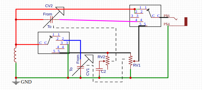 Basic, but with a Dual Pot (2 wafers make it in to a Face 1P13T Capacitor selector)  Then while your not using the Pot as a Pot it can be a Capacitor |
|
|
|
Post by newey on Nov 28, 2021 15:53:42 GMT -5
Found a bit of time over the Thanksgiving Holiday weekend, and so the "Esquire" is currently dismembered. Realized some issues I had forgotten about from when I first built it. I had reused some old dime-sized pots, these were split-shaft, but I had set-screw Tele barrel knobs, which of course never really fit correctly. And, although the theme of the guitar was "all black", when I built it I was unable to find black string ferrules or a black output jack w/ black washer and hex nut screws. It had originally sported a black football jackplate (the body does not have the vintage Tele recessed jack), but I had swapped that out for a chrome one when I needed the black one for my grandson's "Transformers" themed guitar. So I now I found black ferrules, a black jack, nut and washer, and a new black jackplate. So only the pickup screws and switch mounting screws are not black, but once it's back together, a bit of black nailpolish will take care of those. I also am replacing the pots with 250K sealed Bourns 24mm pots, and I ordered some split-shaft Tele-style knobs. Good afternoon to work on guitars, it's a flippin' blizzard outside here at the moment.  Anyway, so based on the foregoing, I have the following values: C1 = .015µf C2 = .033µf (tone pot cap) C3 = .0047µf C4 = .0015µf Do those values sound reasonable? Not sure if I have the smaller values in the parts bin, I may have to do some more shopping. . . |
|
|
|
Post by newey on Dec 11, 2021 0:29:45 GMT -5
Slow progress. Got everything dismembered and got the new Bootstrap pickup installed. Shielded the control cavity FWIW. Started wiring tonight but my cheapo soldering iron bit the dust. Off to pick up a new one tomorrow . . . 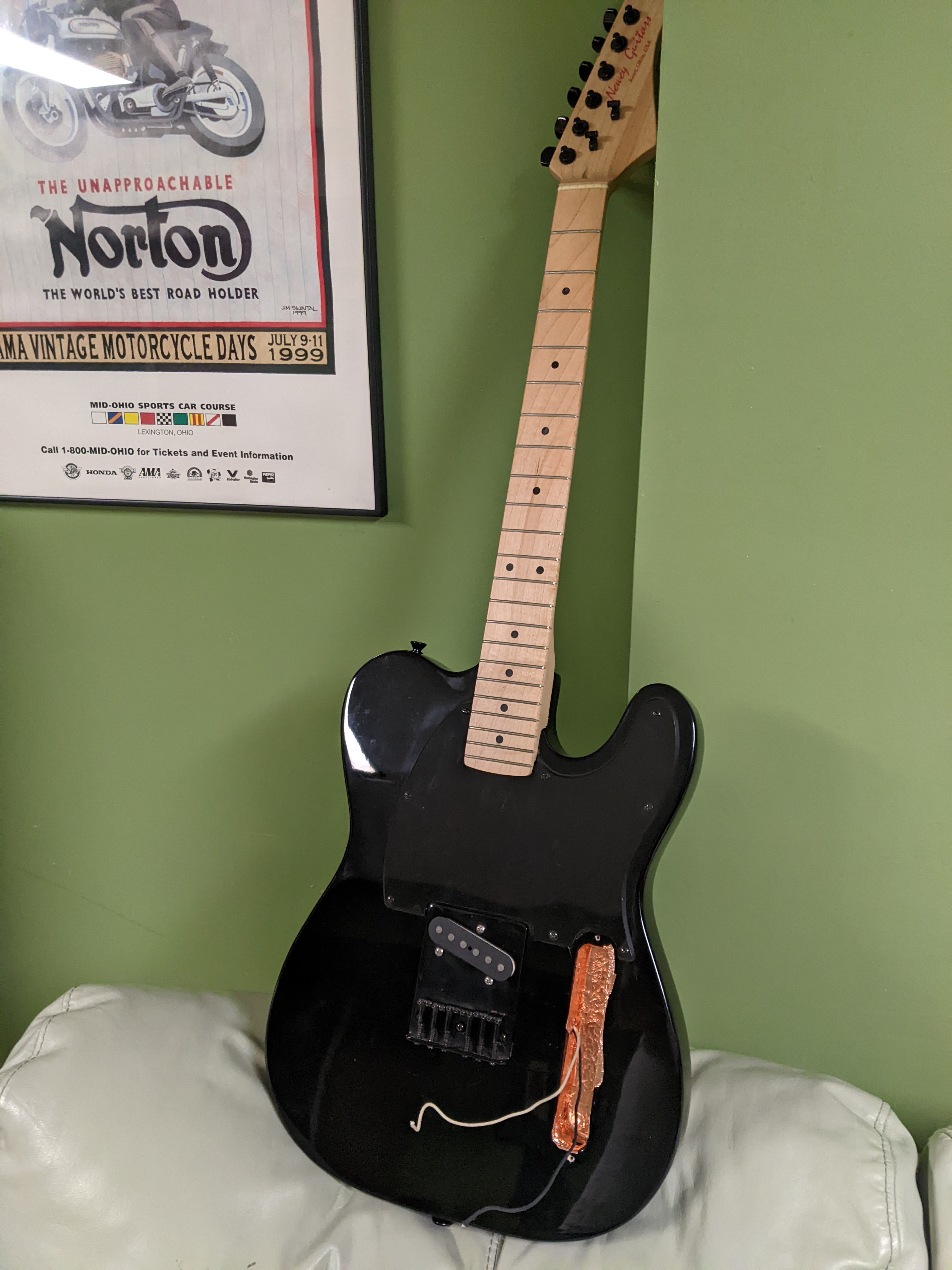 |
|
|
|
Post by newey on Dec 20, 2021 22:36:56 GMT -5
This started out as a thread about wiring this thing, but it's morphing into a build thread. Anyway, got the wiring to the half Superswitch done as far as I can go without working in the guitar. The big cap is C1= 0.015µf; C3 is 0.047µf; C4 is 0.0082µf. C4 was going to be .0015, but I had a bunch of the 0.0082s, so I went with that. 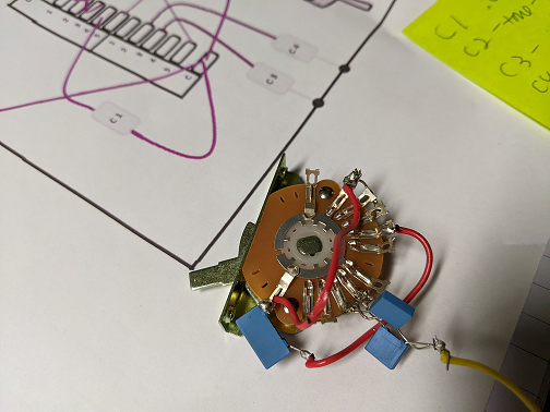 |
|