aramis
Rookie Solder Flinger

Posts: 14
Likes: 0
|
Post by aramis on Apr 13, 2021 21:47:49 GMT -5
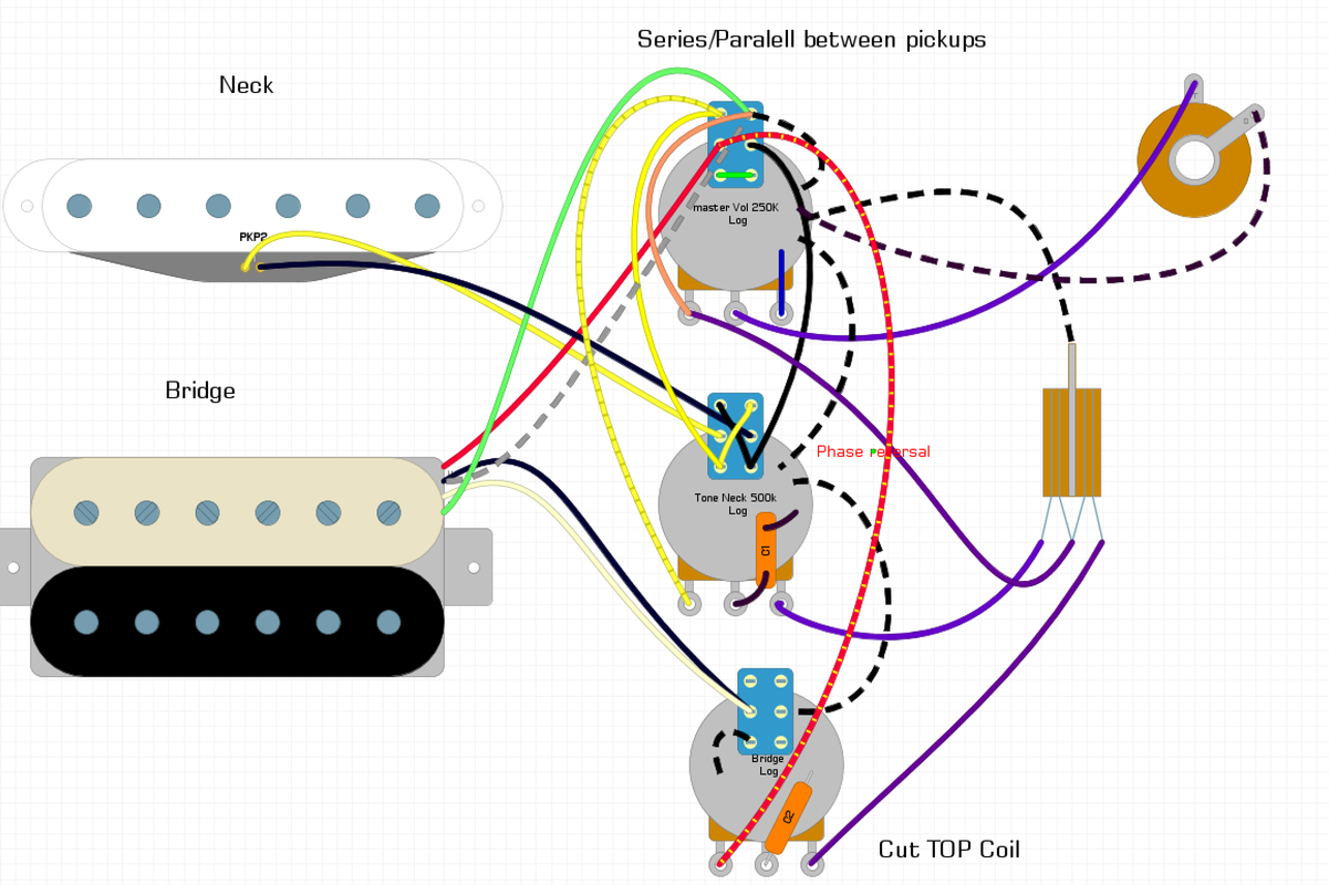
Hello all, a couple of months ago I made a post about using a push pull pot as tone control in one position and a bass control in the other, I realized that there were many downsides to this idea and have since scrapped it. long story short I have a new design 1 vol , 2 tone, series/parallel between pickups on vol, upper coil cut on tone 1, & a phase toggle between pickups on tone 2. I am hoping someone can check my diagram to ensure everything is grounded properly, as things got a bit hairy between the phase and the series, I also heard that you can boost your split coil using a small valued resistor (I have access to a 4.7, 2.2 & 10K at the moment) but I am at a loss as to how I would do that. Here is a link to the google doc containing the image, there is a legend below that explains the colour coding I used to stay organized, docs.google.com/document/d/1yYt7jFpfqNIkUOqT5aDVowbhjlTGSPlItUxdvECHr8Q/edit?usp=sharing I appreciate all help, let me know if I need to be more specific or if my diagram is too hard to read, or if you spot some other glaring error/have suggestions for optimization have a great day! Aramis |
|
|
|
Post by newey on Apr 14, 2021 5:32:13 GMT -5
First off,let's post your diagram directly so we can talk about it without having to click through to the link:  OK, sorry aramis, but it's back to the drawing board.  There are a number of errors there. First off, let's trace the neck pickup wiring. The 2 wires, yellow and black, first go to the phase switch- all good there. But from there, the 2 wires go to the series/parallel switch, where they connect to the center, i.e., common lugs of the push pull. When the switch knob is pulled into the "up" position, the 2 wires are connected together by a jumper wire between the 2 poles of the switch, thereby shorting that pickup to itself, providing no sound in that position. With that series/parallel switch in the "down" position, the neck pickup wires connect to the bridge pickup's "hot" and "ground" wires, which is what we would want to do for a parallel connection- but then, the two now-connected pickups are wired to the volume pot, and then to the output, so the 2 pickups will always both be "on" in parallel with the switch down. Your 3-way switch seems to not be selecting between the pickups, but is just selecting between tone controls. There may be other issues,I always give up listing things after three problems/errors, as anything more probably means a complete rework anyway. The basic order of things here should be that each pickup connects to its tone control (but at the neck, the phase switch goes in beteen the pickup and its tone pot). You will need to separate the tone pots as well, using a separate capacitor for each one, they can't share it like on a Strat. From the tone pots, it will then go to the switching. As for the switching, you need to decide whether you will have the series/parallel switch override the 3-way switch (meaning that pulling the P/P up will put both pickups in series regardless of where the 3-way switch is set), or if it will work with the 3-way, in which case the series connection will only be made when the 3-way is in one particular position (usually the neck position, but could be in the bridge position- cannot be in the center, however.) I do applaud that you attempted a diagram rather than asking one be provided. We'll get this worked out. To start, please look at any of our diagrams from the schematics section (which have been vetted, for the most part) and find a diagram of the wiring to a series/parallel switch between 2 pickups. Trace out the signal path, and I think you'll see where your wiring went astray. |
|
aramis
Rookie Solder Flinger

Posts: 14
Likes: 0
|
Post by aramis on Apr 14, 2021 8:34:35 GMT -5
thanks! I'll get back to work  |
|
aramis
Rookie Solder Flinger

Posts: 14
Likes: 0
|
Post by aramis on Apr 14, 2021 10:39:42 GMT -5
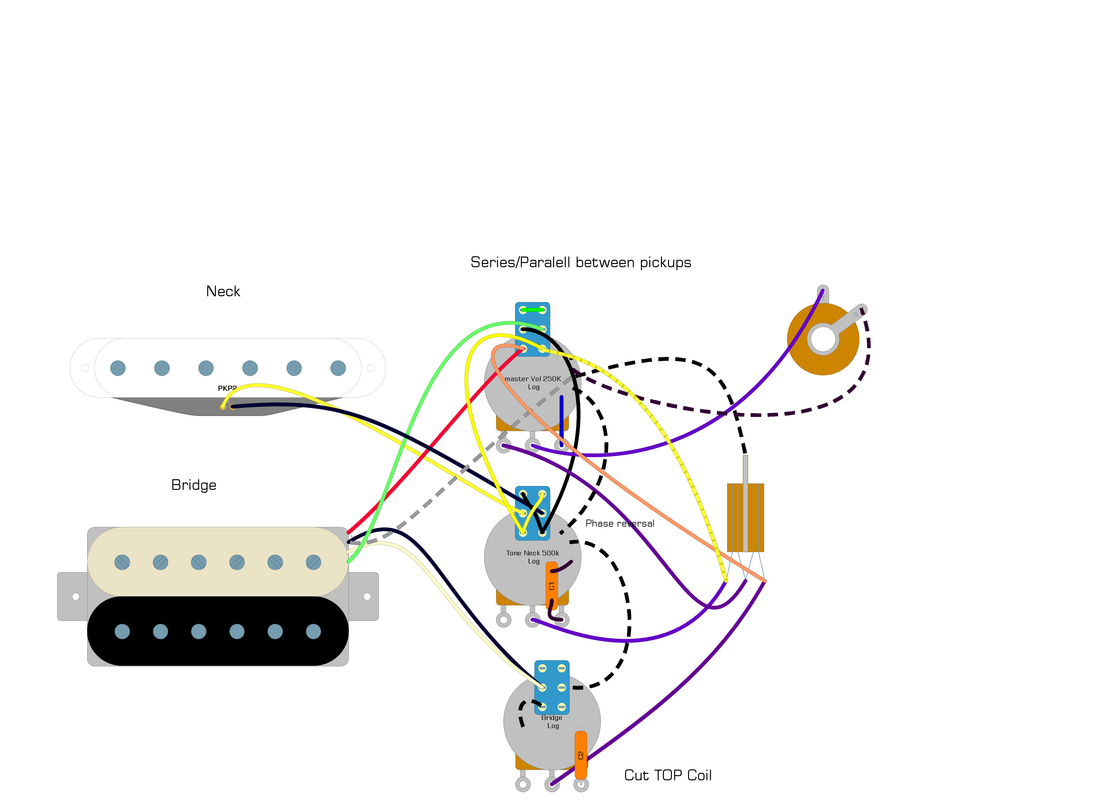
 Updated diagram, I looked at the schematics board, and did my best to make the prescribed changes I think the bridge pickup to tone connection might be a bit hairy. Below is the legend for people in the future, in case the google doc breaks or something and for easier thread reading The Humbucker is dimarzio wiring: Red=NS, Black=NF White=SS Green=SF, Vol 250K Tones 500K * 2 Dashed Grey= bare Purple= Signal wiring Yellow= hot single coil Black= Ground single coil Dashed black= grounding wired purple= signal wires From top to bottom:Volume, Neck tone, Bridge tone There is also a treble bleed circuit (not pictured as it’s busy enough already) The treble bleed it a 470pf cap in parallel with a 220K resistor and in series with a 27 k resistor (sorry if I'm slow to reply, I am also studying for university finals) |
|
|
|
Post by newey on Apr 14, 2021 11:32:12 GMT -5
OK, still issues with the series/parallel switch.
First, the good: Your phase switch is correct, and your coil-cut switch is fine provided that it is the coil with the red/black wires that you want to be the single coil (I don't know off the top of my head whether that is the "North" or "south" coil on a DM or which one, screw vs slug, but if that is the one you want, you're good to go there).
However, you still haven't wired the tone pots as I suggested, and the series/parallel switch is still a no-go in this version. In the latest diagram, in the one position, the bridge green wire is connected to both ground and output at the same time, and so is shorting that pickup, and the neck pickup isn't connected to output in either position of the p/p switch.
And, the 3-way switch won't switch between your pickups unless the pickups are connected to it, which they aren't.
I would be happy to do a diagram for you, it may be a day or two. But first I need you to answer this question:
Basically, your order of components here will be pickup>>>tone pot (wired like on an LP, essentially, but without the Vol)>>>>phase switch on the neck side, none on bridge>>>>3-way switch>>>>Volume pot>>>>output jack. Where the series/parallel swithc goes depends on your answer to the above question.
Also, not sure that a master volume pot will work well with the series/parallel wiring and the individual tone controls, now that I look a bit further. WOuld/could you substitute a dual-gang pot for the volume?
|
|
aramis
Rookie Solder Flinger

Posts: 14
Likes: 0
|
Post by aramis on Apr 14, 2021 13:21:48 GMT -5
Ok, so conceptually I am struggling with how to wire individual tone controls, I figured that by putting the control in front of the selector switch, I could separate the signals until they reach the volume pot (clearly that's now how these things work). the other half of this is that I'am thinking of the humbucker NS as the hot and the SF as the ground to a single coil most of the resources I was observing are made to work with a humbucker, so I'm trying to parse out the two coils from the diagram so that I can interpolate the single coil into the context (tricky to do). the last conceptual issue I have there is how to get my signals and grounds out of the series circuit to where they need to go (volume for ground I believe, and signals to the tone (but seeing as I have issues with wiring that component you can see how I am a bit stuck  ) I'll be giving it another shot shortly  Re: your specific questions 1 I prefer the series circuit to override the toggle 2 I will not be able to get a hold of a dual ganged pot 3 yes a diagram would be deeply appreciated, making them myself is good practice though  Again thanks for your help and patience -Aramis |
|
aramis
Rookie Solder Flinger

Posts: 14
Likes: 0
|
Post by aramis on Apr 16, 2021 19:41:32 GMT -5
 I hope this is closer, still not sure on the series but I think I have the tone pots correct  |
|
|
|
Post by newey on Apr 18, 2021 18:07:16 GMT -5
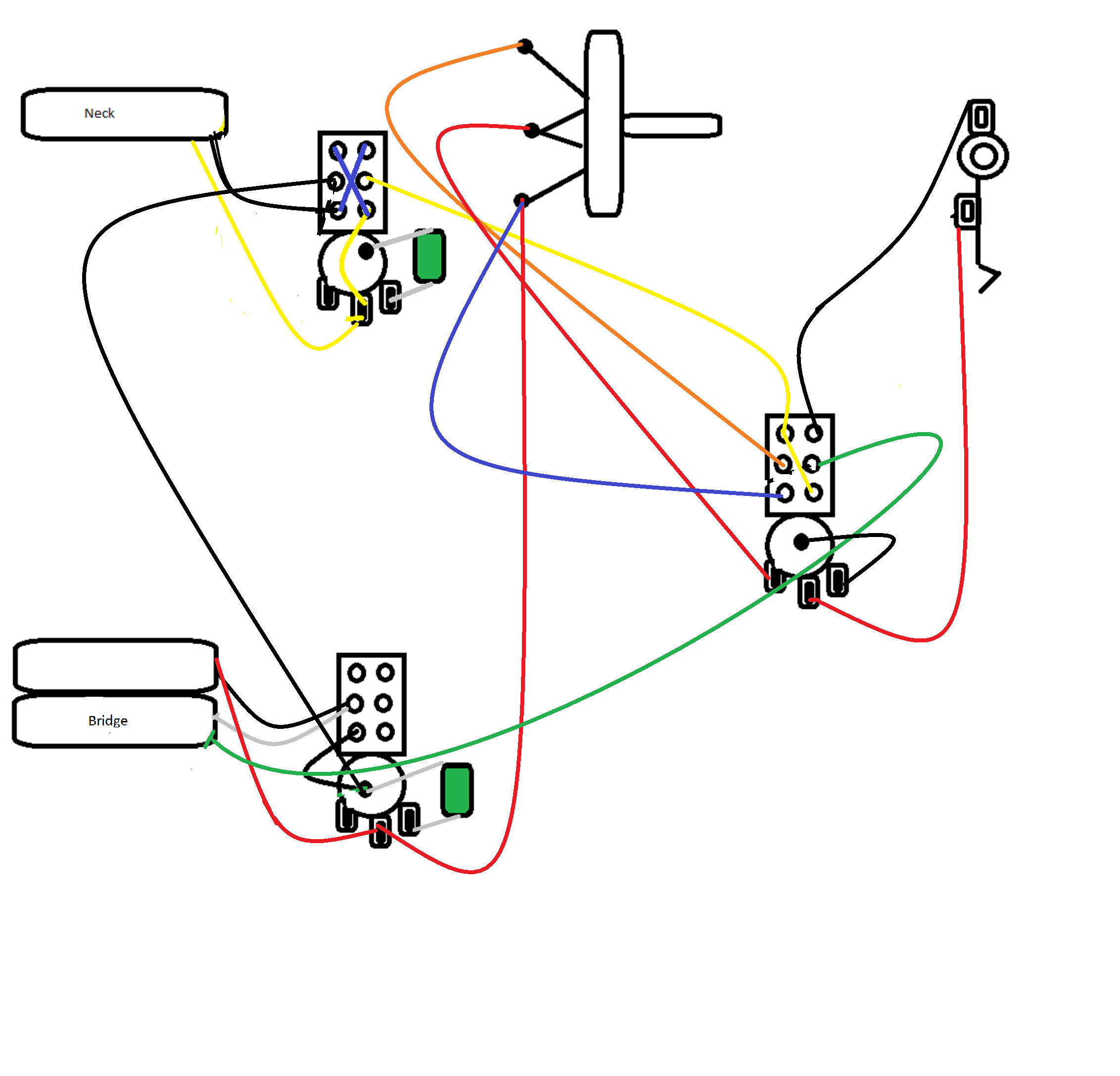
Here's what I was thinking. Let's get someone to check it before you dive into soldering it. Note that I have omitted some of the grounding for clarity. I show all the pickup grounds but I have omitted tying all the pot backs together and omitted the bridge/string ground. Of course, if you are doing a star grounding scheme, this will be different anyway.  Sorry for all the wiring spaghetti, I could have laid it out more efficiently. Probably best if you redraw it assuming it checks out OK. EDIT:OK, my mistake, the above won't work with the coil split when in series mode. Let me get back to the drawing board there. But I think you can see what I was meaning about the tone control wiring and the series/parallel wiring. |
|
aramis
Rookie Solder Flinger

Posts: 14
Likes: 0
|
Post by aramis on Apr 18, 2021 19:30:08 GMT -5
yeah that does make a lot more sense, I will wait as you suggested, and I will make a complete version after my biochemistry exam tomorrow :/ <stress>
thanks a million!
|
|
aramis
Rookie Solder Flinger

Posts: 14
Likes: 0
|
Post by aramis on Apr 20, 2021 22:57:14 GMT -5
Exam done!! Do you think I can get away with your schematic or should I sit tight?
|
|
|
|
Post by newey on Apr 21, 2021 5:29:31 GMT -5
No, sit tight, I need to redo it. Give me a day or so.
|
|
|
|
Post by newey on Apr 23, 2021 7:45:50 GMT -5
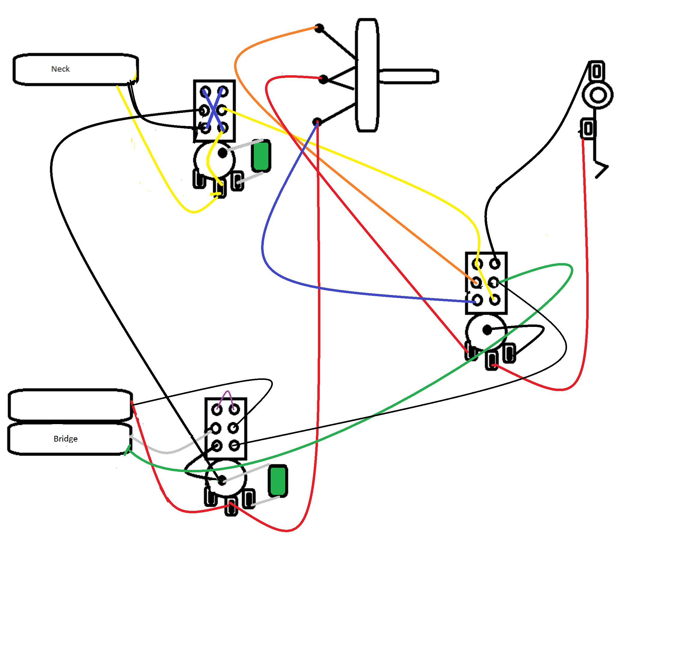
aramis- OK, here's v2.0:  The only thing that has changed is the wiring of the coil-cut switch. Also note that, as on the original diagram, the green wire connects only to the series/parallel switch- it is shown crossing over the volume pot, but I didn't want you to think it connected there. Again, let's get another set of eyes on this before you start wiring. I think it's OK now, but hey, I was wrong the first go-'round . . . Thanks for your patience.
|
|
aramis
Rookie Solder Flinger

Posts: 14
Likes: 0
|
Post by aramis on Apr 28, 2021 17:57:38 GMT -5
I'm wiring this at the moment, is the jack properly grounded it looks like it's only grounded in the down position, is this correct? can I ground the volume push pull to the casing and ground my jack to the tail of the selector which also grounds to the volume pot casing?
|
|
|
|
Post by newey on Apr 28, 2021 18:38:17 GMT -5
I'm wiring this at the moment, is the jack properly grounded it looks like it's only grounded in the down position, is this correct? can I ground the volume push pull to the casing and ground my jack to the tail of the selector which also grounds to the volume pot casing? As I said when I posted the first diagram, I omitted a number of the ground wires. If you are grounding things to the back of the pots, then all the pot shells need to be connected together, and then connected to the jack sleeve. If you are using some form of star grounding, then all the grounds collect at that point, and are then wired to the jack sleeve. I appreciate that you're anxious to get going, I'm sorry no one popped into this discussion to give it a second look-see. I'd hate to think you wired it up and I had led you astray with some error. |
|
aramis
Rookie Solder Flinger

Posts: 14
Likes: 0
|
Post by aramis on Apr 28, 2021 18:51:18 GMT -5
It's going well so far, I have a chain going from jack, tone, tone and then star grounding at the volume, I grounded the series circuit to the casing so I am now wiring the switch and the jack, I have a good feeling  thanks for your help, will update on how it went! |
|
aramis
Rookie Solder Flinger

Posts: 14
Likes: 0
|
Post by aramis on Apr 28, 2021 23:42:52 GMT -5
So it worked... for the most part, all my potr are reverse taper which I just discovered  ... the neck tone dosen't work when the push pull is engaged I think that means I wired my phase switch upside down (this is the only one I really care about), the split works as advertised and so does the series switch. so all in all a success??? |
|
|
|
Post by newey on Apr 30, 2021 7:26:46 GMT -5
Well, let's call it a partial success at best . . .
As for the pots being reverse taper, that would be odd, reverse taper pots are pretty rare, I doubt
that you would order some by mistake. Do you perhaps mean that they operate in reverse fashion?
As for the phase switch affecting the neck tone pot, the tone pot is wired before the phase switch, so I don't understand how the position of the phase switch would affect the neck tone. Does the phase switch work, that is, are the pickups OOP when you have both operating?
|
|