xlunacy
Rookie Solder Flinger

Posts: 13
Likes: 2
|
Post by xlunacy on Apr 20, 2021 4:00:13 GMT -5
Hello,
First post here  Seeing the quantity of wiring diagrams, I think I'm at the right place.
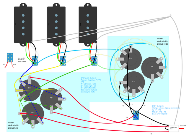
I wanted to design a switching system for a 3 pickup bass, that would allow most of the combinations you can think of (single pickups, 2 pickups in series / parallel, 3 pickups with different combinations....) I came up with this idea, that seems to do what I'm after (excluding 3 pickups in series, or in parallel, and also not considering phase switching).
Since this would be the first diagram that I've made, I'd like it to be reviewed before going into production 
Basically it's just one 6P3T switch to change the pickups' order (assigning P1 / P2 / P3 with bridge / middle / neck in different orders), and a standard DPDT to decide how they are combined. Each pickup can be run in either series or parallel, as an added bonus  (I'll probably ditch the single coil option) I've tried to recreate the 2 (top and bottom) 12 log wafers of the 6P3T switch, hopefully this is clear enough.
I've also attached complementary diagrams.
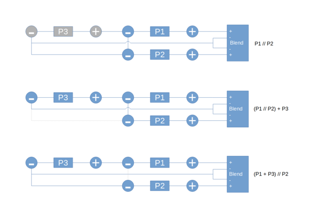
 Visualization of the combinations :
Switch II :  Thanks a lot for your help  |
|
|
|
Post by newey on Apr 20, 2021 5:36:39 GMT -5
xlunacy-
Hello and Welcome to G-Nutz2!
Your diagram is beautifully drawn, but too small to read. When I enlarged it, I lost too much resolution and everything was blurry.
Also, your flow-chart diagram for "Switch II" at the bottom refers to "blend" controls; I'm not seeing those on the diagram.
Your series/parallel switches for each pickup look fine, but that's all I can see for now. So, if you could enlarge this a bit, I would appreciate it.
|
|
xlunacy
Rookie Solder Flinger

Posts: 13
Likes: 2
|
Post by xlunacy on Apr 20, 2021 6:38:20 GMT -5
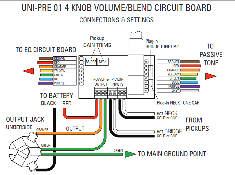
Thanks for the welcome, and the quick answer  The blender is part of the onboard preamp (lower right corner white box). It will be a John East Uni-Pre 4, in case it matters.
Here is the full size diagram !
I'm also adding a full resolution picture for the second diagram :
 |
|
|
|
Post by newey on Apr 20, 2021 10:37:42 GMT -5
Much better, I can see what you're doing now. Would also be helpful to have the lugs numbered, or at least a notation as to the common lugs.
With the blender being part of a "black box" in the preamp, with no way of knowing how it is internally connected, I am not sure how that will work with your series settings. Probably no way to know until you try it and see. Typically, however, blenders are wired differently for series blending as opposed to parallel blending. So, just a head's up that this may present issues.
Sorry, until you enlarged it I didn't see that you were using 3-position switches with the North coil intended for the middle position. Depending on how it is done, the single coil option may also present issues with the series settings. I also have no way of knowing which coil is the North one. As shown, the center position on the switch will leave the unused coil "hanging from hot", which may or may not contribute to noise.
I assume if you eliminate the coil-cut setting, you will just be using 2-position DPDTs?
|
|
xlunacy
Rookie Solder Flinger

Posts: 13
Likes: 2
|
Post by xlunacy on Apr 20, 2021 10:57:22 GMT -5
Awesome, thanks for the feedback !
The lugs are numbered, but difficult to see. I've increased the size of the numbers. Basically red and black wires out of the rotary and going to preamp / switch II are the common.
Concerning the blending, the preamp's blender will always "see" P1+ and P2+, and blend them together in parallel.
Series settings (III) is really just adding P3 behind P1. So no series blending here ! Could be seen as (P3 + P1) // P2 ; see "Pickup II" diagram in my first post.
Hopefully I'm understanding the point you're raising  |
|
xlunacy
Rookie Solder Flinger

Posts: 13
Likes: 2
|
Post by xlunacy on Apr 20, 2021 11:05:08 GMT -5
As shown, the center position on the switch will leave the unused coil "hanging from hot", which may or may not contribute to noise. I tried to make it so that the unused coil is shorted, and connected to the used coil's cold, is this what you meant by "hanging from hot" ? Is there another way to make it work ? Just to be thorough, I assumed a type-1 switch, as pictured here :
I assume if you eliminate the coil-cut setting, you will just be using 2-position DPDTs? I will ! I assume the wiring will be the same  |
|
|
|
Post by newey on Apr 20, 2021 11:24:32 GMT -5
If a "Type 1" 3-way DPDT switch exists, I've never seen one. What you call "Type 2" is the only way I've ever seen those. We have had long discussions as to whether other types of these do exist, but I don't recall if anyone was actually able to ever verify that a "Type 1" as you describe actually exists.
So I was assuming Type 2 when I reviewed your diagram. If you already have the switches, check them first to be sure. If you eliminate the single-coil setting and just use 2-position switches, then your switches are correct for the series/parallel settings as I said originally.
I can see your numbering now. Give me a chance to take a look at this. You may be right about the blender seeing only parallel connections, still trying to wrap my head around what you're doing here.
|
|
xlunacy
Rookie Solder Flinger

Posts: 13
Likes: 2
|
Post by xlunacy on Apr 20, 2021 11:58:49 GMT -5
If a "Type 1" 3-way DPDT switch exists, I've never seen one. What you call "Type 2" is the only way I've ever seen those. We have had long discussions as to whether other types of these do exist, but I don't recall if anyone was actually able to ever verify that a "Type 1" as you describe actually exists. So I was assuming Type 2 when I reviewed your diagram. If you already have the switches, check them first to be sure. If you eliminate the single-coil setting and just use 2-position switches, then your switches are correct for the series/parallel settings as I said originally. I can see your numbering now. Give me a chance to take a look at this. You may be right about the blender seeing only parallel connections, still trying to wrap my head around what you're doing here. I've only learned about this stuff recently using the Seymour-Duncan resources, so I really thought type-1 was the common one (as used in their tutorials). No worries though, this setting will most likely disappear anyway... But in case it does not, I know all I have to do is to mirror the switches horizontally 
Thanks a lot for taking the time to review this !
|
|
xlunacy
Rookie Solder Flinger

Posts: 13
Likes: 2
|
Post by xlunacy on Apr 21, 2021 9:28:53 GMT -5
Remade Switch II as a type-2 switch, and removed single-coil option 
 |
|
xlunacy
Rookie Solder Flinger

Posts: 13
Likes: 2
|
Post by xlunacy on Apr 26, 2021 19:47:19 GMT -5
Bumping this, in hopes of getting some feedback !
It helps to consider each layer of switches independently :
- 3 individual standard series / parallel switches (1 / pickup) - 1 rotary 3 position switch (changes pickup order, and provides the 2 wires for the preamp's blender inputs + the 4 other wires for the next switch) - 1 DPDT 3 position switch : connects the colds of the pickups (with P3+ being always connected to P1-) in different ways to achieve the desired combinations
Thanks for your help  |
|
|
|
Post by newey on Apr 26, 2021 20:35:22 GMT -5
Sorry that no one has gotten back to you on this, XL. I've definitely dropped the ball . . .  I have spend some time looking through your diagram, and I haven't found any errors yet, but I am not anywhere near through all of it. But I also confess to not fully understanding your diagram here. A schematic would help, there's just too much going on in the wiring diagram. But even more than that, another set of eyes (or two, even . . .) would be a big help (Hint, Hint  ) |
|
xlunacy
Rookie Solder Flinger

Posts: 13
Likes: 2
|
Post by xlunacy on Apr 27, 2021 5:19:38 GMT -5
Thanks for taking the time to review this  I've never done a schematics diagram, sorry if this is badly done, I have no real idea  Blue square is the rotary switch, green square is "switch II" dpdt on-on-on. White block is the preamp with blender.
 |
|
|
|
Post by newey on Apr 27, 2021 6:02:26 GMT -5
Your schematic is fine, as far as its drawing- and very helpful.
With the understanding that we don't know what is happening inside the "black box" (or, as it happens, a white box) of the preamp/blender, your schematic traces out OK to my eyes. But let's get a second opinion before you start soldering. This is a pretty complex scheme.
As for the "white box", the schematic makes my eyes want to draw a straight line from P1+ to the jack sleeve, which would be wrong, but I realize that you simply haven't designated the + and - inputs and outputs to the box, as you did on your original diagram. So, a bit visually deceiving on the schematic, but assuming you follow the preamp's designations for input and output, that should be fine.
BTW, one thing that makes this one difficult to trace out is that there are only combinations of 2 or more pickups- no pickup is ever "on" just by itself. I don't know that we've seen a scheme with no single pickup settings.
|
|
xlunacy
Rookie Solder Flinger

Posts: 13
Likes: 2
|
Post by xlunacy on Apr 27, 2021 6:40:57 GMT -5
I've shifted the wires around the preamp box and labelled some of them to make it easier for the eyes 
Concerning the single PU options, I've excluded them because they can already be achieved using the extreme positions of the preamp's blend on the P1 // P2 configuration, and since P1 or P2 can be any of the 3 pickups, it means there are already several ways to solo any pickup !
Thanks again for reviewing all of this, it helps a lot !!
 |
|
xlunacy
Rookie Solder Flinger

Posts: 13
Likes: 2
|
Post by xlunacy on May 9, 2021 11:55:15 GMT -5
No other response, so I have forwarded my charts and diagrams to my luthier, I guess we'll find out on the spot if it works as intended. Thanks a lot newey for your help  I'll make sure to report here when the project is finished. |
|
Deleted
Deleted Member
Posts: 0
Likes:
|
Post by Deleted on May 25, 2021 9:43:26 GMT -5
Am I missing the GROUND here
|
|
|
|
Post by newey on May 26, 2021 13:06:49 GMT -5
Am I missing the GROUND here Ground is through the "white box" of the blender circuit to the jack sleeve. 2 grounds go in, one comes out. |
|
xlunacy
Rookie Solder Flinger

Posts: 13
Likes: 2
|
Post by xlunacy on May 26, 2021 13:24:23 GMT -5
Hey,
Thanks for chiming in 
I don't really know how to represent them on a schematics diagram... But each element will be properly grounded (knobs, pickups, cavities, jack, bridge) ! I represented the ground on the wiring diagram (gray wire of each pickup).
The wires going into the preamp "white box" are not grounds, but pickup "colds" ! By manipulating what the preamp sees as a cold, I can switch between the different combinations.
The preamp has a dedicated grounding point :
 |
|