|
|
Post by jalfmorch01 on Jul 28, 2021 15:08:27 GMT -5
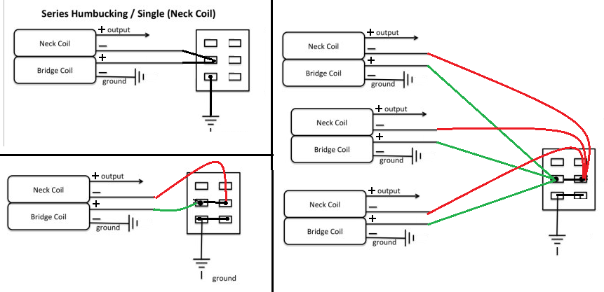
Hello everybody, it's been a few days since i have seen the Seymour Duncan schematic to coil split 3 humbuckers at the same time and I didn't understand it (or like it) at all, so I was wondering if there's a more simple way to do it with a DPDT or a Push Pull and I get to this. Could anyone please help me and check if it's correct?  |
|
|
|
Post by newey on Jul 28, 2021 17:52:22 GMT -5
Hmmm.
I haven't, and I couldn't find anything like that on the SD website. Can you link to the diagram to which you are referring, or post a copy?
This may also depend on what type of pickup switching you are employing. I'm not sure coil splits can be done the way you show it. In the non-split position, all the series links for all 3 pickups are going to be joined together. If you are turning the series HBs on/off via grounding the coils, or by hanging from "hot" (i.e., by disconnecting the ground side, the would ground the series junction of the pickup(s) you want to have "on". Perhaps this would work if the "off" pickups were completely disconnected, I dunno.
|
|
|
|
Post by jalfmorch01 on Jul 28, 2021 18:21:47 GMT -5
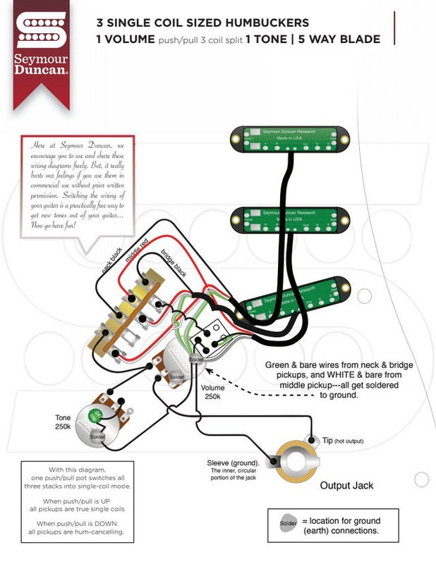
Hmmm. I haven't, and I couldn't find anything like that on the SD website. Can you link to the diagram to which you are referring, or post a copy? This may also depend on what type of pickup switching you are employing. I'm not sure coil splits can be done the way you show it. In the non-split position, all the series links for all 3 pickups are going to be joined together. If you are turning the series HBs on/off via grounding the coils, or by hanging from "hot" (i.e., by disconnecting the ground side, the would ground the series junction of the pickup(s) you want to have "on". Perhaps this would work if the "off" pickups were completely disconnected, I dunno. Sure, here's the diagram im talking about  If it helps for something, the reason im trying to split the coils the way I show here  Is because 1.- I don't understand SD's diagram   and 2.- 'Cause I want to attach the triple coil split into the Freeway 5B5 wiring |
|
|
|
Post by JohnH on Jul 28, 2021 18:27:30 GMT -5
Hmmm. I haven't, and I couldn't find anything like that on the SD website. Can you link to the diagram to which you are referring, or post a copy? This may also depend on what type of pickup switching you are employing. I'm not sure coil splits can be done the way you show it. In the non-split position, all the series links for all 3 pickups are going to be joined together. If you are turning the series HBs on/off via grounding the coils, or by hanging from "hot" (i.e., by disconnecting the ground side, the would ground the series junction of the pickup(s) you want to have "on". Perhaps this would work if the "off" pickups were completely disconnected, I dunno. These kind of wishes generally need one of these ideas: 1. a switch with three poles, one to separately split each pickup without linking hem to each other (problem with the diagram above) 2. more than one switch, eg one switch does two, the other does one pickup, or separate switches for each pickup 3. if you only select two pickups at a time, eg like on a normal Strat, you can use a two-pole switch for coil cut where one pole is moved from say B to N pickups as set by the main 5-way. |
|
|
|
Post by jalfmorch01 on Jul 28, 2021 19:08:47 GMT -5
Well my first intention was to have the mentioned coil splitting applied in the Freeway 5B5 schematic, shown right here Wich works like: 1.-B 6.-NxM (X=series) 2.-B+M 7.-N+B 3.-M 8.-NxB 4.-M+N 9.-N+B+M 5.-N 10.-BxM  So, I know im asking for way way too much, but it's possible to adapt this diagram (The coil splitting part)  To this one??  |
|
|
|
Post by newey on Jul 28, 2021 20:38:09 GMT -5
OK, so the SD diagram avoids the problem I noted, and does what JohnH said- it uses the other pole of the 5-way switch to switch between the N and B series junctions, with the other pole of the DPDT switching the middle pup series junction. But the diagram you have for the Freeway switch shows that you have used all the poles, you don't have an extra one to switch the N and B series junctions. You could, as suggested, get a 3PDT switch to split all 3 HBs at once. But that would be a toggle switch, not a push/pull pot. Or, you could choose to just split any 2 of the 3 HBs with the DPDT, and live with the omission. Another consideration is that, as shown, the SD diagram splits all 3 HBs to the same coil, so a 3 pole switch could do a better job of hum-cancellation when in split-coil mode. |
|
|
|
Post by jalfmorch01 on Jul 28, 2021 22:16:51 GMT -5
You could, as suggested, get a 3PDT switch to split all 3 HBs at once. But that would be a toggle switch, not a push/pull pot. Now Im wondering, what about an S1 switch? Could it work for the 3 HBs? |
|
jalfmorch
Rookie Solder Flinger

Posts: 3
Likes: 0
|
Post by jalfmorch on Jul 29, 2021 0:36:24 GMT -5
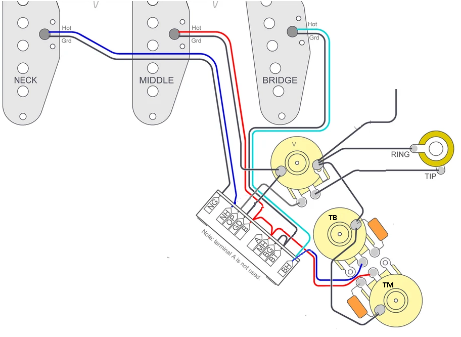
Im sorry if im a bit stubborn with my idea  , but I remade the diagram this time with the S1 switch, could this one work?  |
|
|
|
Post by newey on Jul 29, 2021 5:02:42 GMT -5
That looks fine, jalfmorch01. I hadn't thought of the S-1. However, now that you're working with a more capable switch, no reason not to maximise hum-cancellation. If you think you'll be using the N + M and M + B combos a lot, as on a regular Strat-ish setup, it would make sense to split the middle pickup to the opposite coil, so that those 2 combos will be hum-cancelling. (if you would use the N + B combos more than the combos with the middle pickup, then you can do the same with either the neck or bridge pickups instead). There are 2 ways to do so. The simple "down and dirty" way is that, instead of the black wire grounding the middle pickup series junction, run a wire to the "hot" output instead (either to the output lug of your switch or direct to the volume pot CCW lug.) Some folks object to doing it this way, however, because they dislike the idea of shorting a pickup to its own "hot" line (why they dislike it will involve a long-winded explanation which I will skip here). The "fancier" way is to wire the middle HB "inside out". To do so, instead of the green and white wires joining at the S-1 switch, the red and black wires go there, white goes to output and green to ground. The red/black pair is then grounded by the S-1 switch, via the black wire just as it is shown on your diagram. If you do rewire the middle pickup as suggested, note that since you have a phase switch on the bridge pickup, if the phase switch is set to OOP, then the M + B combo will not be hum-cancelling. If you wanted the OOP settings to be hum-cancelling, you would keep the wiring as shown on your diagram. |
|