|
|
Post by cem on Aug 23, 2021 9:21:50 GMT -5
Hi guys. I was wondering if this Phostenix diagram could be modified so that the series option would be on 3rd position instead of 2nd position when the switch is pulled? If so, how can i make it work? Thanks in advance!  |
|
|
|
Post by newey on Aug 23, 2021 12:10:19 GMT -5
Hi, cem- Yes, you can do so. I'll write a verbal description, which you can then use to modify the diagram. If you can't follow my verbal description, let me know and I'll do a diagram, but this is just a matter of moving 3 wires. 1) There is a pink wire on the diagram that runs from lug #2 on the bottom half of the 3-way switch to the push/pull switch. Disconnect both ends of that wire and discard it. 2) The yellow wire (Bridge +) stays connected as it is now, but add a jumper wire from lug #1 on the bottom half of the 3-way to lug #2 on the bottom half of the 3-way (the lug from which you just disconnected the pink wire). 3) On the top half of the 3-way switch, a blue wire is connected to lug #2 and a green wire is connected to lug #3. Swap those two wires around so that the green wire is connected to lug #2 and the blue wire is connected to lug #3. All other wiring remains the same as it is shown on the diagram. Note that another option is to have the series setting override the 3-way switch, so that pulling the p/p up gives you the series setting regardless of the position of the 3-way switch (as per reTrEaD here). |
|
|
|
Post by cem on Aug 23, 2021 14:01:20 GMT -5
Thanks newey. Your instructions are very clear. But overriding the 3-way switch makes a lot more sense to me now. But the problem is that i dont understand any of this   How do i read this? |
|
|
|
Post by newey on Aug 23, 2021 14:39:11 GMT -5
cem- RT's diagram above is a schematic, not a wiring diagram, and it difffers a bit in that he represents the 3-way as an LP-style toggle switch ; yourt Tele switch is a bit different. Let me work up a wiring diagram of this using your Tele switch, it should make more sense then.
|
|
|
|
Post by newey on Aug 24, 2021 5:40:55 GMT -5
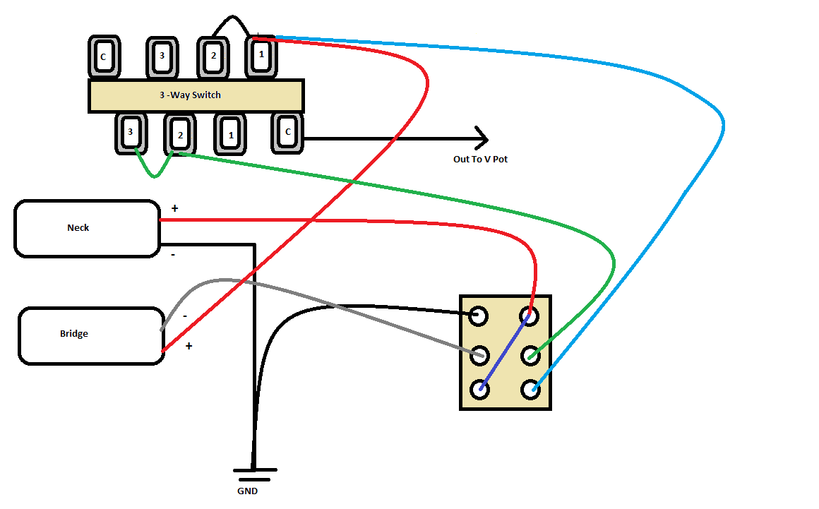
I think this will do the trick, but let's get someone else to verify it first.  |
|
|
|
Post by reTrEaD on Aug 25, 2021 21:35:44 GMT -5
I think this will do the trick, but let's get someone else to verify it first.  Looks good except for the missing connection between the two poles of the pickup selector. |
|
|
|
Post by reTrEaD on Aug 25, 2021 21:59:59 GMT -5
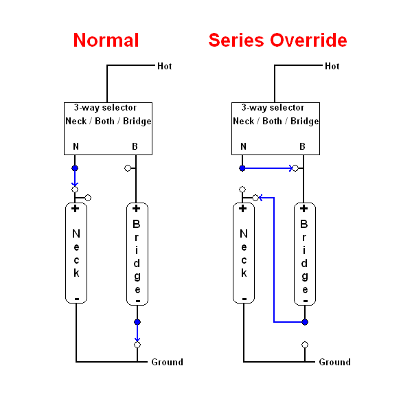
 How do i read this? The six circles are the lugs of a DPDT switch. The circles filled in blue are the poles. The circles filled in white are the throws. The blue lines and arrowheads indicate which throw each pole is connected to, in each mode. They represent the internal connections within the switch. One pole is assigned to the Neck connection of the three-way switch. The other pole is assigned to the (-) wire of the Bridge pickup. On the left (Normal Mode) diagram, the Neck connection of the three-way switch is connected to the (+) of the Neck pickup. The (-) wire of the Bridge pickup is connected to ground. It matters which position the Pickup Selector is in. Either the just the Neck pickup or Both pickups in parallel or just the Bridge pickup will be selected. On the right (Series Override Mode) diagram, the Neck lug of the Pickup Selector is connected to the Bridge lug of the Pickup selector (and also connected to the + wire of the Neck pickup). The (-) wire of the Bridge pickup is connected to the (+) wire of the Bridge pickup. It does not matter which position the Pickup Selector is in. The (+) wire of the Bridge pickup will always be connected to Hot. And the (-) wire of the Bridge pickup is connected to the (+) wire of the Neck pickup, creating the series link. |
|
|
|
Post by cem on Aug 26, 2021 3:54:02 GMT -5
reTrEaD thanks for the explanation and the verification as well. newey can you update the diagram when you have the time? Also, in the diagram i posted there is a cover ground wire in green which goes to the back of the pot and then to the 3 way switch. Do i do the same thing here? Can you add that as well, along with the missing connection that retread is talking about?
|
|
|
|
Post by newey on Aug 26, 2021 5:51:32 GMT -5
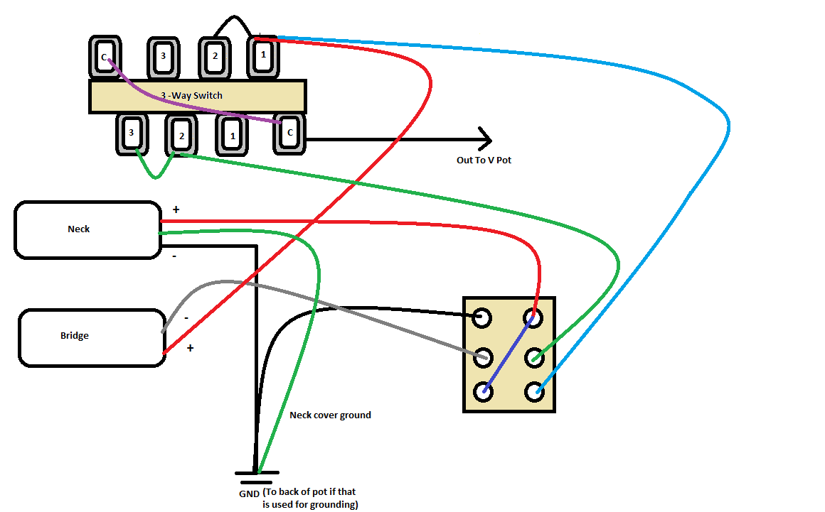
Looks good except for the missing connection between the two poles of the pickup selector. OOPS! Yes, you need a jumper between the common lugs. I'll update the diagram in a bit. As for the green ground wire, I simplified my diagram by not showing the pot wiring, as that does not change from your diagram. The green wire is grounded, and where I have marked the ground on the diagram goes there as well. I also omitted the bridge ground as well. |
|
|
|
Post by cem on Aug 26, 2021 10:10:12 GMT -5
Ok. So just to clarify, we've got red and blue wires connected to the 1st (rightmost) lug of the upper side of the 3 way switch on your diagram. The neck cover ground wire is supposed to be connected to the same lug after being connected to the back of the pot right? There is also a jumper from 1st to 2nd lug. That's one crowded lug right there  |
|
|
|
Post by newey on Aug 26, 2021 12:12:38 GMT -5
The neck cover ground wire is supposed to be connected to the same lug after being connected to the back of the pot right? There is also a jumper from 1st to 2nd lug. That's one crowded lug right there No. Just ground the cover wire to the back of the pot (or wherever you're doing your grounding). In the previous diagram, there was a green wire from the top-right lug (numbered as #1 on my diagram) to the back of the pot to ground that connection. In the revised diagram, we are not grounding that lug. Also, just to be clear, referring to "upper right" on the switch is as per the diagram, not necessarily as per your switch as it actually is. I labeled the common lugs, you need to be sure which lugs are the commons on your switch before soldering it up. |
|
|
|
Post by newey on Aug 26, 2021 12:17:51 GMT -5
Revised.  |
|
|
|
Post by cem on Aug 26, 2021 12:47:45 GMT -5
Awesome. Thanks again newey. You are a saint!!! |
|
|
|
Post by newey on Aug 26, 2021 15:59:09 GMT -5
Please inform my wife . . .  |
|