ls1986
Rookie Solder Flinger

Posts: 8
Likes: 0
|
Post by ls1986 on Aug 26, 2021 12:37:02 GMT -5
Hi everyone,
Thanks for being so helpful with my last question. I'm trying to get some more understanding of how 3-Way and 4-Way switching on a Telecaster works so that I can, hopefully, come up with a different switching order that fits what's most intuitive for me. But I'd like to understand it not just ask someone to do the work for me, so I can do it on my own in the future.
Here's what I'm lacking an understanding of:

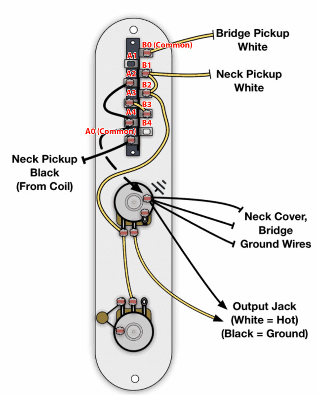
(Hopefully that image upload worked) I've seen multiple examples of wiring diagrams where the output wire that connects to the volume pot is connected to only one lug on the selector switch, and not a common lug. My question is how exactly is this resulting in an output signal when the selector switch is on a position that doesn't connect to the lug with the output wire? From this example I can understand how position 2 is getting to output, and position 1 is getting there with just an extra "hop" via the wired connection from B1 to B2. But positions 3 and 4 have me lost.
Some diagrams I see have the output wired to a common lug, so my understanding is it's sort of "always on" regardless of the switch position, but those seem to actually be the minority.
I've gone down a whole rabbit hole of additional questions like this, but I think this is a good one to start with that might explain the others.
Thanks in advance for any help.
|
|
|
|
Post by newey on Aug 26, 2021 15:11:17 GMT -5
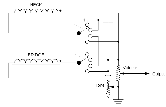
I don't know where that diagram came from, but it is not the standard Tele wiring. I can't tell what it is doing because the lettering for the lower common lug is obscuring the connections there. But it depicts not a 3-way switch but a 4-way switch (also called a "Baja Tele" switch), and the Tele 4-way switching is typically used to give a series option- so that's probably what is intended with that diagram, but again, can't really see a couple of the connections clearly. The standard tele wiring using a 3-way switch would have both commons lugs wired together, and then from one of the commons to the Vol. pot and thus to output. So, both commons go to the output. Then, the Neck "hot" connection (white in your diagram) is wired to lugs 2 and 3 on one side of the switch, and the bridge "hot" is wired to lugs 1 and 2 on the opposite side of the switch. Both of the pickup black wires are then wired to the grounding point. If it's the 4-way switch wiring that you want explained, there are various ways of doing that, but here at G-Nutz2, member sumgai posted the definitive version:  This is a schematic, not a wiring diagram, so if you aren't conversant with reading schematics, let us know. It may, in fact, be the same as the diagram you posted, but again, I can't make out some of the details on that diagram. This schematic is simplified from the actual Baja Tele wiring, which also incorporates an S-1 switch for out-of-phase sounds, and so the wiring diagrams for an actual Fender Baja Tele will differ from this one. You said that your problem was that you wanted a different switching order. What is it that you are wanting? |
|
ls1986
Rookie Solder Flinger

Posts: 8
Likes: 0
|
Post by ls1986 on Aug 26, 2021 18:03:55 GMT -5
So the diagram in my initial post is from Fralin Pickups. Here is the switch configuration without the lug labels. The idea with that one is the following pickup selection order:
1- The Bridge
2- Bridge and Neck in Parallel
3- Bridge and Neck in Series
4- The Neck
What I'm looking to do is have the combinations of both pickups be on the outside positions of the switch, but I prefer the parallel up by the neck and series by the bridge, those just sounds more similar to me:
1- Bridge and Neck in Series
2- The Bridge
3- The Neck
4- Bridge and Neck in Parallel
I have a diagram below I've mapped out of what I think would work for that, but since I still don't exactly understand even how the more usual 4 way switch diagrams are getting to output in each switch position I could be WAY off base, and probably am.
Or if that's not possible:
1- The Bridge
2- Bridge and Neck in Series
3- Bridge and Neck in Parallel
4- The Neck
|
|
ls1986
Rookie Solder Flinger

Posts: 8
Likes: 0
|
Post by ls1986 on Aug 26, 2021 18:19:59 GMT -5
The other thing that may very well be missing from my diagram is a jumper between the common lugs. I just notice most of the wiring diagrams I've seen for a 4-way switch don't have a jumper. I'm not sure if that's because one isn't needed, or if it's just to keep the diagram a little cleaner visually. That could be a factor in why it isn't making sense to me
|
|
|
|
Post by ashcatlt on Aug 26, 2021 18:46:21 GMT -5
You know, I think you got that right. The Tele 4-way switch is a proper DP4T switch where each lug is discrete to itself, and you really just need to move the connections from one lug to another in order to move the different selections around. That is, you wanted to swap position 1 with 3 and positon 2 with 4, so you swapped the things that were connected to lug 1 on each side with those on lug three, and those on lug 2 with lug 4, and that's exactly how that works. So lets go through it maybe? 1) The bottom of the bridge pickup is permanently connected to the jack sleeve. The top is connected via the jumper to the bottom of the neck pickup. The top of the neck pickup is permanently connected to the jack tip, so that completes our circuit: sleeve>bridge bottom>bridge top>neck bottom>neck top>tip. The two pickups are in series. 2) Bridge bottom is still connected to the sleeve. The top of the bridge now connects to the top of the neck pickup, which is still connected to the jack tip. There is a complete circuit there: sleeve>bridge bot>bridge top>tip. But the bottom of the neck pickup is not connected to anything. There is no circuit that way, so there should be no contribution to from the neck pickup, so this would be bridge only. That neck pickup IS "hanging from hot", though, and can be expected to add a bit of noise we might not prefer. The scheme that newey posted above actually helps that in the respective position by shorting the bottom of the neck to the top. You could accomplish that by jumpering B2 to A2, and I'd suggest doing so. 3) The bridge bottom is still connect to the sleeve, but the top now goes nowhere. It is "hanging from ground" which we do all the time and is nowhere near the noise concern of "hanging from hot", but anyway, there's no circuit through the bridge pickup, so it contributes nothing. The neck bottom is now connected to the sleeve through the switch, and we already know that its top is connected to the tip, so there's a circuit there. This is neck only. 4) Here the bottom of both pickups connect to the sleeve, and both of their top wires are connected to the tip. There is a circuit through each, but neither goes through the other. They are in parallel with one another, the standard Tele "middle" connection. Hope this helps. Holler if you have questions. |
|
ls1986
Rookie Solder Flinger

Posts: 8
Likes: 0
|
Post by ls1986 on Aug 26, 2021 23:37:17 GMT -5
Thanks so much. I'll admit I had to re-read that and visually follow the pathing you described multiple times to be sure I was really following what you were saying, but that helps tremendously.
I guess the only thing that's still throwing me off in your reply is about position 2, bridge only. I definitely want to avoid any noise issues that might be associated with the neck pickup "hanging hot." But won't putting a jumper from A2 to B2 create continuity on the neck pickup from top and bottom?
Lastly, on the topic of reduced noise, I followed a 60's style wiring scheme for the tone capacitor connection between the two potentiometers because it's supposed to have a lower signal to noise ratio. I also want a treble bleed installed on the volume pot so I don't lose too much high end when rolling off the volume. I haven't seen any examples of the two options being done simultaneously, but really most diagrams I see don't use a 60s wiring model for the tone cap. Can the two be done together or is that a problem?
|
|
ls1986
Rookie Solder Flinger

Posts: 8
Likes: 0
|
Post by ls1986 on Aug 26, 2021 23:38:21 GMT -5
Oh, and if I'm following what you said, there's no need to create a jumper between the common lugs on the switch. Is that correct?
|
|
|
|
Post by ashcatlt on Aug 27, 2021 18:38:12 GMT -5
But won't putting a jumper from A2 to B2 create continuity on the neck pickup from top and bottom? Well, yeah, that's kind of the point. The bottom of the neck pickup is connected to its own top. The bottom of that pickup isn't otherwise connected to anything else, so all you're doing is shorting the pickup so that it can't contribute any sound OR noise. The sound we get out of the pickup is the potential difference between top and bottom, but when they are both in the same place, there is no difference, so no sound. I can't imagine any way of wiring a working tone control that would make any meaningful difference in noise either way, and I'm sorry but I'm not the best to tell you about treble bleeds. You neither need nor want the jumper between the commons. That would just screw everything up. Standard Tele 3-way wiring is a different thing. In that, normally the bottom end of both pickups is permanently connected to jack sleeve ("ground"). The jack tip is connected to both commons, and then each side of the switch decides whether its respective pickup's top gets to that tip or not. |
|
ls1986
Rookie Solder Flinger

Posts: 8
Likes: 0
|
Post by ls1986 on Aug 27, 2021 20:18:34 GMT -5
Thanks for all the help. I really appreciate it.
|
|