|
|
Post by frets on Nov 6, 2021 12:27:07 GMT -5
Newey,
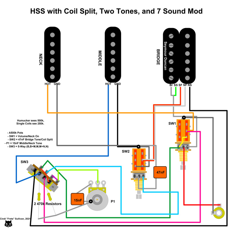
I’ve been contemplating the resistor on a switch that leads to ground. These would be in relation to “Humbucker sees A500k, Single Coil sees A250k.” I have a mod for an HSS that runs a 470k resistor from the middle on the switch to ground and the same for the neck. Is this wrong?
|
|
Deleted
Deleted Member
Posts: 0
Likes:
|
Post by Deleted on Nov 6, 2021 12:57:57 GMT -5
I think your going to have to draw it to know where this resister is and what it effects
|
|
|
|
Post by newey on Nov 7, 2021 7:34:21 GMT -5
Newey, I’ve been contemplating the resistor on a switch that leads to ground. These would be in relation to “Humbucker sees A500k, Single Coil sees A250k.” I have a mod for an HSS that runs a 470k resistor from the middle on the switch to ground and the same for the neck. Is this wrong? As @angellahash said, I don't know what "middle lug" means without knowing the type of switch we're talking about. The diagram you reference was a Tele set-up with a 4-way switch, which doesn't have a "middle lug" to my way of thinking. |
|
|
|
Post by frets on Nov 7, 2021 9:10:51 GMT -5
|
|
Deleted
Deleted Member
Posts: 0
Likes:
|
Post by Deleted on Nov 7, 2021 9:57:05 GMT -5
Im going to ignore the TONE
and the Volume becauase the Volume is a PD which makes things complex
1) Neck with 470K, So 1 / ( [ 1/DC Resistance Neck ] + [ 1/470K ] )
2) Neck with Middle and 470K, So 1 / ( [ 1/DC Resistance Neck ] + [ 1/DC Resistance Middle ] + [ 1/470K ] + [ 1/470K ] )
3) Middle with 470K, So 1 / ( [ 1/DC Resistance Middle ] + [ 1/470K ] )
4) Middle with Bridge, So 1 / ( [ 1/DC Resistance Middle ] + [ 1/DC Resistance Bridge ] + [ 1/470K ] )
5) Bridge
Oh i see the Neck can be brought in to play Direct to VOLUME
NOTE when ever the Neck is brought in to play then you would need to add on
1 / ( [ 1/DC Resistance Neck ] + [ 1/470K ] )
So ignoring the DC Resistance and looking on the output and the effects of the Resisters on the Volume
INPUT--------------------------470K-----------------------------GROUND
INPUT------Resistance A-------OUTPUT--------Resistance 500-A----GROUND
10) Resistance A=0 so between Input and Ground is 250K Full Signal
5) Resistance A=250K so but still between Input and Ground is 250K but half the signal and between Output and Ground is 250K
1) Reistance A=500K so between input and ground is 250K No Signal
Shouldnt it be inbetween INPUT and OUTPUT on the VOlume
|
|
Deleted
Deleted Member
Posts: 0
Likes:
|
Post by Deleted on Nov 7, 2021 11:31:54 GMT -5
To get a true 250K / 500K pot .. you need two 500K Pots in parallel and to turn it on and off .. i would need to Turn on/off two ends SW1 you have bringing in the Neck, the only reason is when the Bridge as its already there with the Middle and on its own. I think maybe best to bring in the BRIDGE and to make the Volume to 500K Then you also have SW2 that makes it in the NORTH pickup on the Bridge This can be change to Bring the NORTH in to play without effecting the Volume ie staying at 250K BUT if both up you will get NORTH with 500K N,N+M,M,M, BLANK 1) N+(Humbucker 500K or NORTH 250K) 2) N+M+(Humbucker 500K or NORTH 250K) 3) M+(Humbucker 500K or NORTH 250K) 4) M+(Humbucker 500K or NORTH 250K) 5) (Humbucker 500K or NORTH 250K) I've not planned in the TONE yet, i can but hope it wont effect things  My Lapto is going a bit wappy so hard to draw.. JUST example I couldnt explress the 5 way switch as i wanted to .. But i use both sides  |
|
|
|
Post by ashcatlt on Nov 7, 2021 19:41:58 GMT -5
Wait what's the question? In bridge only position, it only sees the V and T pots. In B+M, both B and M see that resistor parallel to the V and T pots. In M only, the M sees the resistor parallel to the V and T. In B+N, both pickups see both resistors in parallel with each other AND the V and T. In N only, the N sees its resistor parallel the V and T. We're back in that situation where anything parallel to anything is also parallel to everything that is parallel to that thing. I mean, put it together and see if you like it, I guess, but...
|
|
Deleted
Deleted Member
Posts: 0
Likes:
|
Post by Deleted on Nov 8, 2021 2:40:10 GMT -5
Like Ash suggested maybe best to put it together and you can see it happening dont need to Solder in Pickups just use a a Resister for each pickup That way it stay in the mind than a load of MATHS and being TOLD yes or no NOW ya learning like a Boy would  learn by what nearly kills you and doesnt work as you want it. |
|
|
|
Post by unreg on Nov 9, 2021 11:31:48 GMT -5
|
|
Deleted
Deleted Member
Posts: 0
Likes:
|
Post by Deleted on Nov 10, 2021 1:45:40 GMT -5
Hmmm no
Just thinking that just solder in pickups just use a 100k 200k 400K resisters so you can see how the switching and volume is working
Just a way to do the maths easier
But knowing Frets she would make it with her solderless connectors
|
|
|
|
Post by gumbo on Nov 13, 2021 8:24:54 GMT -5
...just need a routing in the body that's big enough to contain a breadboard.....  |
|
|
|
Post by unreg on Nov 16, 2021 11:16:19 GMT -5
Kneading bread, inside a guitar cavity 😯, is frowned on by me 😉; and I don’t even know much.
|
|
|
|
Post by newey on Nov 16, 2021 12:19:17 GMT -5
Steve Allen: "Is it bigger than a breadboard?" (And, if you get that joke, you're officially old  ) |
|
|
|
Post by sumgai on Nov 16, 2021 12:52:12 GMT -5
Steve Allen: "Is it bigger than a breadboard?" (And, if you get that joke, you're officially old ) OK, Boomer!  |
|
|
|
Post by gumbo on Nov 17, 2021 7:17:03 GMT -5
|
|
|
|
Post by unreg on Nov 17, 2021 16:06:42 GMT -5
gumbo, you don’t knead bread with a breadboard? You prefer to prototype electronics? What about banana bread, or genuine homemade bread? Tastes so good! 🍞❤️ Sry, I didn’t know about electronics on a breadboard. 😔
|
|


 learn by what nearly kills you and doesnt work as you want it.

 )
)

