|
|
Post by stevewf on Nov 16, 2021 4:48:37 GMT -5
![]() ![]() Here's a summary of this our findings on the Free-Way Blade switches so far. Props to Yogi B for intense cross-checking and for highlighting traces. [Note: There's discussion at Freeway Switch (Blade) that led to this summary post case there's need for background]"Truth Tables":These tables show which terminals get connected within the switch, for each position. Freeway 3B3-01 Truth Table
Position#1 : (OP BH)
Position#2 : (OP BH NH) (GD NG)
Position#3 : (OP NH) (GD NG)
Position#4 : (OP BH A) (GD NH)
Position#5 : (OP A B) (NH BH)
Position#6 : (OP NH B) (BH NG)
 image by Yogi B image by Yogi B Truth Table
Position#1 : (OP BH) (GD BT)
Position#2 : (OP BH MH) (GD BT)
Position#3 : (OP MH)
Position#4 : (OP MH NH) (GD NG)
Position#5 : (OP NH) (GD NG)
Position#6 : (OP BH) (A NG) (B BG)
Position#7 : (OP BH MH NH) (GD BT NG)
Position#8 : (OP NH) (GD BT) (BH NG)
Position#9 : (OP BH NH) (GD BT NG)
Position#10: (OP NH) (GD BT) (MH NG)
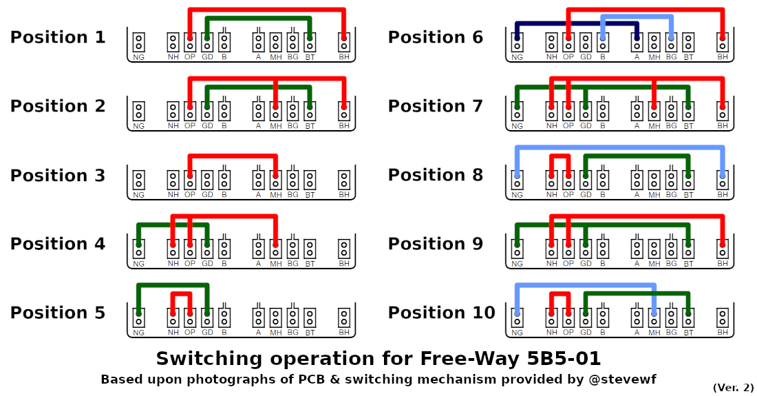 image by Yogi B image by Yogi B Truth Table
Position#1 : (OP BH)
Position#2 : (OP BH 2+)
Position#3 : (OP BH NH 3+) (G3 BT NT)
Position#4 : (OP NH 4+)
Position#5 : (OP NH)
Position#6 : (OP BH) (GD BT)
Position#7 : (OP BH MH) (GD BT)
Position#8 : (OP MH)
Position#9 : (OP MH NH) (GD NT)
Position#10: (OP NH) (GD NT)
 image by Yogi B image by Yogi BWhat I call the "shuttle" moves inside the switch body when the player moves the blade handle. The shuttle carries three sets of contacts, which touch the pads on the switch's Printed Circuit Board (PCB), which makes electrical connections between the terminals. Six pairs of contacts on the shuttle to touch the six pads on the PCB.  Above: The Contact Shuttle shown inside a 5B5-01 switch. The other blade switches have a similar component. 3B3-01 PCB photos:  Above: The PCB of the 3B3-01  Above: 3B3-01, reverse side of the PCB, showing the "jumper" trace  Above: The PCB of the 3B3-01, showing the traces on the reverse side, plus some shading to help see the circuits photos: 
Above: the PCB of the 5B5-01 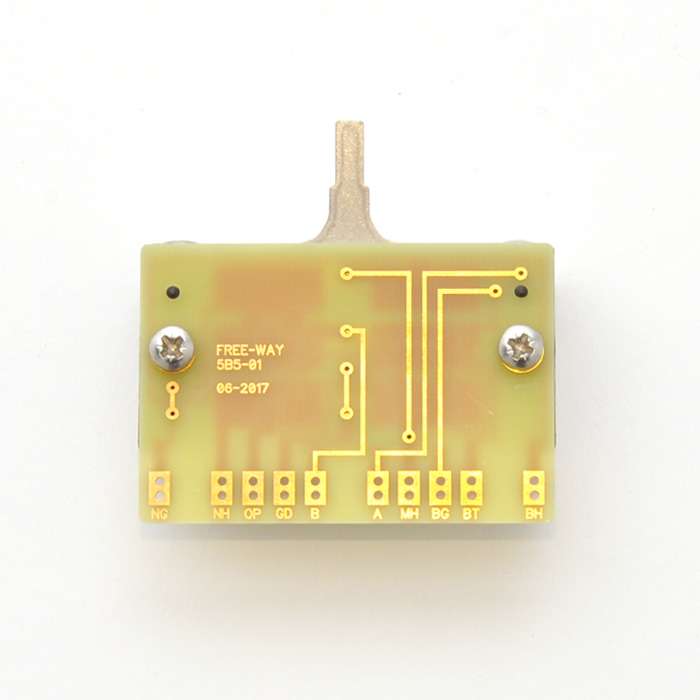 Above: 5B5-01 PCB, reverse side, showing the traces there  Above: the PCB of the 5B5-01 with reverse traces shown, plus position of the shuttle contacts in Position#10 photos:  Above: PCB of the 5B5-02 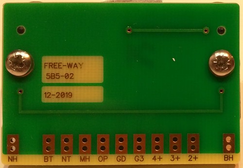 Above: 5B5-02 reverse side of PCB, showing the traces there  Above: PCB of the 5B5-02 with reverse-side traces shown |
|
|
|
Post by stevewf on Oct 29, 2024 16:41:59 GMT -5
BTW, the Free-way 5B5-01 mounting screws are M3-0.50 size (that's 3mm major diameter with 0.50mm thread pitch). The screw length should be between 5mm and 10mm plus the thickness of your mounting surface. It's kinda picky that way. The screw has to reach about 5mm into the chassis, and at 10mm deep, the hole runs into some internal plastic (which is for assembly screws). Example: my pickguard is 1/8" thick, or about 3.2mm, so the screw I use should be somewhere in the range from 8.2mm to 13.2mm long. 10mm would work well, and the switch came with a pair of those, with "oval" heads.  I haven't checked the other Free-way blade switches' screws, but I imagine they're the same as this one's. |
|


