|
|
Post by pete12345 on Jan 17, 2022 12:21:47 GMT -5
It's been quite a while! I've got the guitar bug again after a rough patch, and keen to make some more mods.
I have plans to do a version of JohnH's Strat SP incorporating a capacitor in the parallel out of phase positions- I'll post a diagram once I've drawn it up properly- with the first choice being my old Squier. The way I've sketched it out, it's the bridge-most coil which get the HOoP capacitor, rather than the more bassy coil as is usually done. Any reason why this would be a bad idea?
The only potential problem I can see is the depth of the control cavity needed for the superswitch- my Squier has a relatively thin 41mm body, and it depends if I'm brave enough to carve it out and risk going through the back! Otherwise, I have a HSH Strat clone which I can do a simplified version- with the series/parallel and coil cut (on both humbuckers) but no blend or phase switches.
|
|
|
|
Post by newey on Jan 17, 2022 14:01:44 GMT -5
pete12345- Welcome Back! Which coil gets the cap is strictly a matter of preference, by all means try it to see whether you like it or not. As for the cavity depth, you are no longer limited to strictly the Oak Grigsby (i.e., Fender OEM) Superswitch. There are now other manufacturers of 4P5T switches, and some of the import ones may be a bit smaller. Measure carefully and then shop your dimensions around a bit. I'm not sure if the Schaller Megaswitch version is any smaller, we had someone ask that question a while ago but I don't know that we ever got a definite answer.
|
|
|
|
Post by pete12345 on Jan 17, 2022 15:02:54 GMT -5
I thought that would be the case- after all, the idea is to prevent the lows from one pickup from cancelling with the other, so it shouldn't matter which pickup that is.
I've ordered a switch already, so if it doesn't fit then it can go in the HSH guitar and I'll figure out a scheme for that. It only has two controls (V+T) but there's room for three toggle switches between them. I reckon by using a 4PDT switch for the phase, I should be able to rig it so the correct neck coil gets shunted in either combination of pickups.
That being the case, the Squier may end up with a simpler mod I found in my archive, which swaps the middle-only position of a standard setup for neck and bridge in series.
|
|
|
|
Post by jhng on Jan 17, 2022 17:59:31 GMT -5
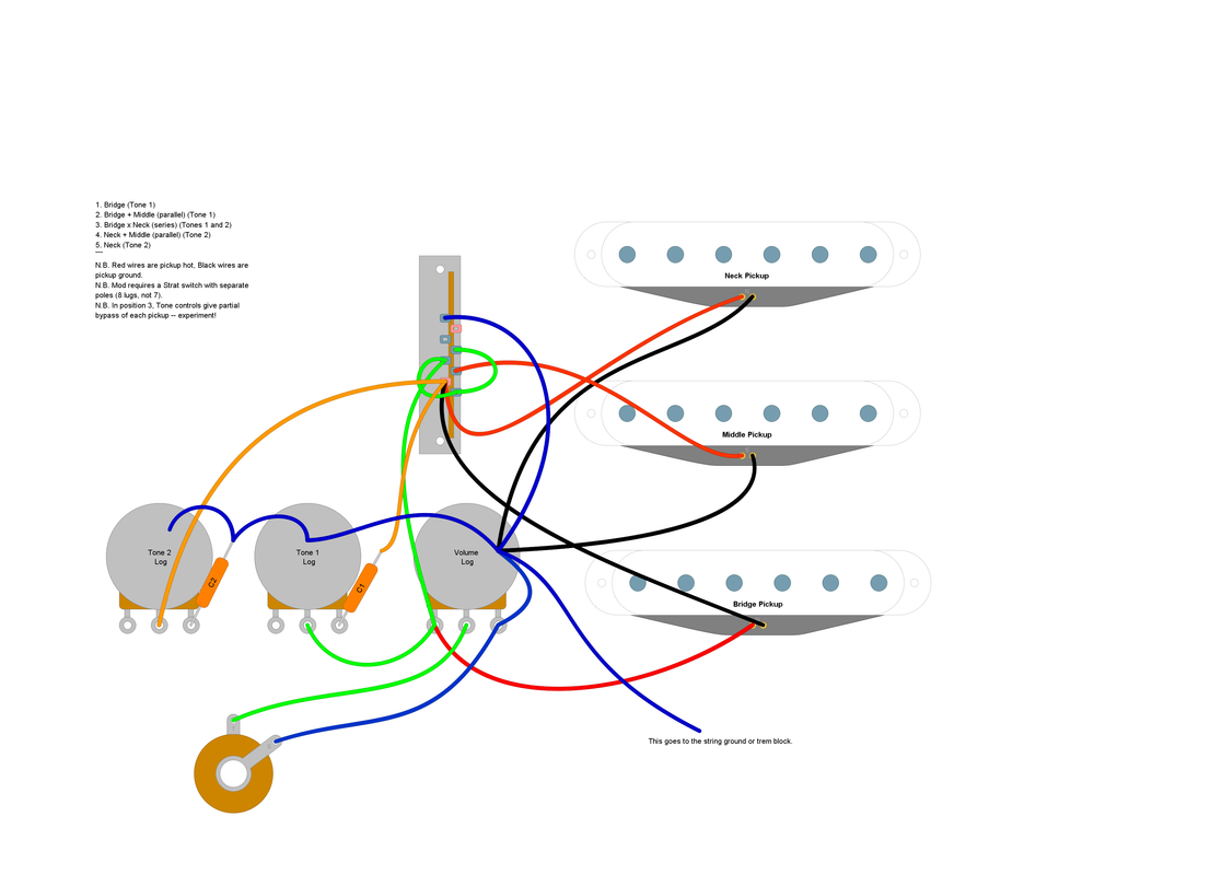
That being the case, the Squier may end up with a simpler mod I found in my archive, which swaps the middle-only position of a standard setup for neck and bridge in series. I worked out a mod very many years ago that uses stock Strat parts to put NxB in the third position of a standard strat, (with the N and B tone controls doing partial bypass in that position). By total coincidence I did fresh layout diagram for it the other day. Here it is, in case it's helpful. However, do check it carefully before you try it as this is a rough draft and not proof-read yet.  |
|
|
|
Post by pete12345 on Jan 19, 2022 16:51:11 GMT -5
I've lifted the pickguard on the Squier to have a look and poked a tape measure inside. Looks like the cavity is deeper around the switch- I measured 35mm which should just about be enough for the switch on order. Worst case, I might have to widen the slot a little which is less daunting than going further down. So project StratSP is go!
Now, what else to do with a HSH? Current setup is as per the stock SSS Strat wiring i.e. no coil splitting. Only two knobs though which does limit things a bit. Also no pickguard on this one so any additional switches would have to go straight through the wood.
|
|
|
|
Post by pete12345 on Jan 21, 2022 14:34:35 GMT -5
I've got a plan for the HSH which shouldn't need too many extra parts. The standard 5-way switch can be wired as a fairly ordinary "autosplit" configuration, giving:
1- Bh
2- Bs+M
3- M
4- Ns+M
5- Nh
So far, so good. My plan is to use a push-pull or single DPDT switch to do two things- switch the bridge pickup on regardless of the 5-way, and with the other pole, disconnect the middle single-cpil and put the neck humbucker in its place. This should give:
1- Bh
2- Bs+Nh
3- Bh+Nh
4- Bh+Ns
5- Bh+Nh
Eight distinct sounds, all pretty useful!
|
|
Deleted
Deleted Member
Posts: 0
Likes:
|
Post by Deleted on Jan 21, 2022 18:12:16 GMT -5
I can't picture it yet..
What do you class as standard 5way switch!
Thinking 2P5T as the strat type would be dam complex
|
|
|
|
Post by newey on Jan 21, 2022 19:46:30 GMT -5
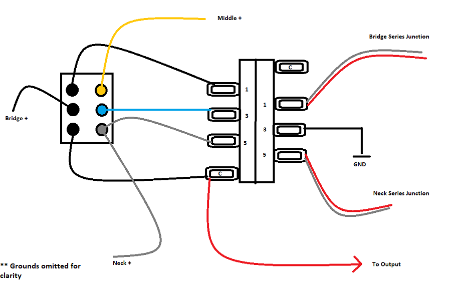
pete12345: I'm with @angellahash, not seeing this with a regular Strat 5-way switch. To do the coil split at both positions 2 and 4, you would need to connect both bridge and neck "series junctions" to lug 3 (numbering the lugs as 1-3-5) on one pole of the switch. The commons on that side either goes to ground or to output, depending on which coil you want split (And, if the pickups are the same, both will split to the same coil unless you wire one of the two "inside out"). So, the DPDT switch then has to switch the other pole's #3 lug between the middle + (for your "Standard Strat" mode) and the neck + (for the mode without the middle pickup). SO, instead of the "truth table" you show, the bottom part with the DPDT switched "on", will give: 1) Br. HB 2) Br. SC + N SC 3) Br. SC + N SC 4) Br. SC + N SC 5) N HB + Br. HB I don't see any way around that result with a standard 5-way switch. If you're seeing it differently, please enlighten me. Also, in this mode, you could make positions 2,3 and 4 hum-cancelling by wiring one HB "inside out", as I said. But you would then lose hum-cancellation with the middle pickup at eithe rposition 2 or position 4.
|
|
|
|
Post by MattB on Jan 21, 2022 20:22:28 GMT -5
I'm with angellahash, not seeing this with a regular Strat 5-way switch. To do the coil split at both positions 2 and 4, you would need to connect both bridge and neck "series junctions" to lug 3 (numbering the lugs as 1-3-5) on one pole of the switch. The commons on that side either goes to ground or to output, depending on which coil you want split (And, if the pickups are the same, both will split to the same coil unless you wire one of the two "inside out"). Lug 1: Bridge series junction Lug 3: Ground or output Lug 5: Neck series junction Common: No connection In position 2, lugs 1 and 3 are connected, splitting the bridge pickup. In position 4, lugs 3 and 5 are connected, splitting the neck pickup. In positions 1,3 and 5 no connection is made. |
|
|
|
Post by newey on Jan 21, 2022 21:27:45 GMT -5
Good job, MattB! Looks like that should work, I didn't spot that. |
|
Deleted
Deleted Member
Posts: 0
Likes:
|
Post by Deleted on Jan 22, 2022 2:09:38 GMT -5
My problem wasn't the layout It was getting both sets with just a 2P2T 1- Bh 2- Bs+M 3- M 4- Ns+M 5- Nh 1- Bh 2- Bs+Nh 3- Bh+Nh 4- Bh+Ns 5- Bh+Nh Can swop M for NH and Bh for position 234 but I'm stuck bring in BH for 5 by using the 2P2T to set points ,  I need another pole on the switch -------- Also if we are using a 5 way switch like suggested, how going to get two outputs. Maybe I should just design a PCB for 2,P5T+5 |
|
|
|
Post by newey on Jan 22, 2022 7:37:26 GMT -5
@angellahash- A picture, as they say, is worth 1000 words . . .  |
|
|
|
Post by pete12345 on Jan 22, 2022 7:48:33 GMT -5
That's the basic idea. As for the autosplit, I've seen the same diagram in a couple of places so assumed it was common knowledge!
I have spotted another variation which would be interesting. Instead of the bridge+ being sent to the output, send it to the unused common terminal on the 5-way, and split by shunting the midpoints to the output rather than ground. That way, with the switch thrown you'd get:
1. Bs
2. Bs+Nh
3. Bh+Nh
4. Bh+Ns
5. (Bh+Ns) in series with the other neck coil.
I guess you'd call that last one half-series or something, but it could be interesting.
|
|
|
|
Post by newey on Jan 22, 2022 10:00:55 GMT -5
5. (Bh+Ns) in series with the other neck coil. I guess you'd call that last one half-series or something, but it could be interesting. Hmmm. Not sure about that. If we think about this using SD colors, both N and Br green wires are grounded. Neck series junction (red/white pair) at position 5 connects together. Bridge black connects via commons to lug 5, where Neck Red/white is connected. Neck Black is connected to output via the other half of the switch. So, I'm thinking you'd have the Bridge HB in series with the white/black coil of the neck HB (would this be in phase???). The green/red coil of the neck would be shorted to ground through the bridge HB, and wouldn't sound. At least, that's the way I see it, maybe I'm wrong. |
|
|
|
Post by pete12345 on Jan 22, 2022 12:32:05 GMT -5
So, I'm thinking you'd have the Bridge HB in series with the white/black coil of the neck HB (would this be in phase???). The green/red coil of the neck would be shorted to ground through the bridge HB, and wouldn't sound. At least, that's the way I see it, maybe I'm wrong. Surely the green/red coil being connected to the bridge HB would be that coil in parallel with the bridge HB? It would be the same as in position 4, except that the white/black coil is no longer shunted, so gets put in series with the (BridgeHB)+(N green/red) combination.  |
|
|
|
Post by newey on Jan 22, 2022 12:56:46 GMT -5
Surely the green/red coil being connected to the bridge HB would be that coil in parallel with the bridge HB? That's what I'm questioning. The red/green neck coil only gets to the output through the neck white/black coil. But the coil is simultaneously grounded through the bridge HB. I dunno, maybe you're right . . . Try it and see what you get, I guess. |
|