syddd
Meter Reader 1st Class
  
Posts: 62 
Likes: 10
|
Post by syddd on Feb 9, 2022 3:45:25 GMT -5
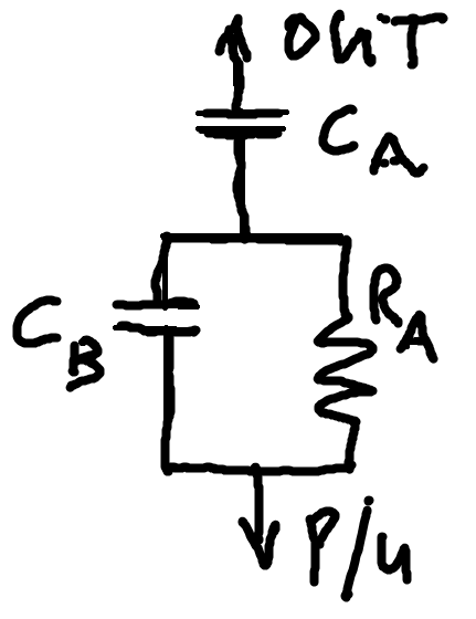
Hello All, I have an RC circuit question as I am trying to simulate a J-bass neck pickup with a P-bass using resistors and capacitors. (I.e. not converting the coils to parallel). So I want to cut some of the low end, cut some of the volume and retain the high end. I have an idea using the following circuit but I need to check that my logic is sound.  Can anyone in layman's terms tell me what happens here? I am theorising the following; 1. that I can choose capacitor C A independently of everything else to cut the low end at any frequency I choose (i.e. it has the same effect on cutting the low end even if the values of Capacitor B and Resistor A are zero). 2. Resistor R A can be tweaked to get the desired output provided the bypass capacitance isn't too high, and; 3. The effective capacitance that bypasses the resistor becomes the series capacitance of capacitors C A and C B i.e. CBypass = 1/ [(1/C A) + (1/C B)] I'm quite sure of my second assumption but my first and third assumptions are a bit flaky in my head. Can anyone confirm if my reasoning is correct? |
|
|
|
Post by reTrEaD on Feb 9, 2022 9:50:57 GMT -5
I am theorising the following; 1. that I can choose capacitor C A independently of everything else to cut the low end at any frequency I choose Okay syddd , let's stop right there. The value of C A to cut the low end at a given frequency is dependent on the parallel loading after that point. To keep things simple, we'll model that as the resistance of the tone control (at max CW) in parallel with the resistance of the tone control (at max CW) in parallel with the input impedance of the amplifier. A Standard P Bass uses 250k pots and the input impedance is approximately 1M. 250k // 250k // 1M = 111.11k To find the value of C A for a given rolloff frequency, use a capacitive reactance calculator to find the capacitance that will have a capacitance reactance of 111.11k at that frequency. This will be the -3dB rolloff frequency and will filter at -6db/octave.
C B // R A can be analyzed in much the same way, however R A works together with the 111.11k load to create a voltage divider. 111.11k / (R A + 111.11k) gives us the voltage division. We can calculate the dB value of the lower "shelf" below the rolloff frequency. I reckon this part of the circuit should serve your needs and you can probably omit C A.
Calculations become significantly more difficult when the tone control is turned CCW from max. |
|
|
|
Post by sumgai on Feb 9, 2022 13:15:37 GMT -5
Calculations become significantly more difficult when the tone control is turned CCW from max. Indeed. I predict that if you were to roll down the tone control, you'd then have a signal deprived of both bass and treble. That newly-minted mid-enhanced signal may or may not meet your desires, but some folks listening to it are not going to be impressed, I'm pretty sure of that. Your call.  HTH sumgai |
|
|
|
Post by JohnH on Feb 9, 2022 16:47:06 GMT -5
Its a tricky problem because the whole circuit involved includes the entire instrument, plus the cable and amp. Luckily we have this: guitarnuts2.proboards.com/thread/3627/guitarfreak-guitar-frequency-response-calculatorGuitarFreak is a spreadsheet that simulates the whole guitar, including specific pickups. There is a bass model included which has a combination of a J and a P bass. You can see how they differ and then experiment with tone contral and bass cut etc to try to match them. You need access to Excel, any version. Or, it runs reasonably well using the excel 97-2003 file, into Libreoffice. |
|