jean
Rookie Solder Flinger

Posts: 16 
Likes: 0
|
Post by jean on Apr 11, 2017 2:05:01 GMT -5
Hi all, I couldn't solve the "klang" problem and despite hours of wiring/rewiring/testing I couldn't make the buffered bypass working on both units I got. I then decided to go to plan B: instead of the Modboard I did install a Mr Fuzzzy from Lee Jackson and a microbooster (clean FET boost) from BECOS. The chain is then now: pickups (both with triple shot system)--> Sustainer-->Mr Fuzzzy--> Microbooster -->Piezo-->stereo output additional features are: the kill-switch (shadow on volume pot), the XY Midi pad, the Tronical system and I'm using two "regular" Humbuckers, the sustainer pickup being used only as driver. The whole monster is working on three batteries (checked with LoBat systems), two of them being operated from the 9 pin switching jack, the third one switched on/off from a solid state relay. My little baby is now fully working and sounding terrific....I'm definitively an happy man  |
|
jean
Rookie Solder Flinger
Posts: 16
Likes: 0
|
Post by jean on Mar 19, 2017 14:22:24 GMT -5
And some pics of the board (ok, not extreme good quality)... Attachments:IMAG3348.pdf (814.92 KB)
IMAG3345.pdf (899.91 KB)
|
|
jean
Rookie Solder Flinger
Posts: 16
Likes: 0
|
Post by jean on Mar 15, 2017 9:12:19 GMT -5
If that can help, here is the provided documentation of the Modboard (generic) and the specific one. Attachments:TB1_lo.pdf (692.47 KB)
MODboards_lo.pdf (695.23 KB)
|
|
jean
Rookie Solder Flinger
Posts: 16
Likes: 0
|
Post by jean on Mar 14, 2017 3:41:13 GMT -5
Hi Sumgai, On the board there are two outputs: buffered and true bypass (one shall choose which one to wire). The on/off function is controlled by a double switch J3 & J4 (where J3 controls the "buffered" output and J4 the "true bypass" one), which from obscure reasons have both to be plugged and switched from the same controller (a DPDT is used to duplicated the switch). To my understanding, the board remains under power to allow the buffered output. Again, I ain't an engineer... but if I understand you correctly, the problem might come from a logic gate (or the lack of it)? Would it help if I attach pics of the board? I cannot myself follow the signal path and understand the compounds of the board  |
|
jean
Rookie Solder Flinger
Posts: 16
Likes: 0
|
Post by jean on Mar 13, 2017 9:17:39 GMT -5
Any suggestion for it?
|
|
jean
Rookie Solder Flinger
Posts: 16
Likes: 0
|
Post by jean on Mar 13, 2017 2:34:29 GMT -5
Some update: I got a second unit for testing and eventually as replacement one. Before installing it in the guitar went to some testing phase using a signal generator and measuring output thru a multimeter (I don't own an oscilloscope, but can get mV AC range, good enough). Unfortunately, I got exactly the same results: - signal out on the "true bypass output" both when effect engaged of disengaged, ok - signal out on the "buffered output" ok when effect engaged but none when disengaged Letting me think it might be a design problem of the board... or I really missed a point  |
|
jean
Rookie Solder Flinger
Posts: 16
Likes: 0
|
Post by jean on Feb 28, 2017 6:57:17 GMT -5
Just to be sure the problem is clear, when the effect us engaged in the "buffered" output does work. When I switch off the effect, then the "normal" output signal from the guitar is almost none.
Thus the board gets power (at least when effect us engaged).
The "true bypass mode" let the output signal going thru without pb.
What I would think of, is that the Board doesn't get power -by some obscure reason- when the effect is off. But I can't figure why... 😖
|
|
jean
Rookie Solder Flinger
Posts: 16
Likes: 0
|
Post by jean on Feb 27, 2017 5:37:45 GMT -5
Definitively waiting forward to your comments then!!!
About the battery negative lug, it is internally -on the board- connected to the "switching jack" one. The latest one is supposed to be the ring of a stereo jack connector for power switching in "standard configuration".
|
|
jean
Rookie Solder Flinger
Posts: 16
Likes: 0
|
Post by jean on Feb 26, 2017 14:12:29 GMT -5
Thanks Newey. I will start by powering the Modboard to check if that the problem! About the diagram, I attached previously pdf file thus is should be easier to read than using the jpg. Tell me if it ain't enough. Surprisingly, indeed all the other parts are working. Additionally, I had LoBat systems to my 3 batteries in order to monitor their charge. It's been quite challenging  |
|
jean
Rookie Solder Flinger
Posts: 16
Likes: 0
|
Post by jean on Feb 25, 2017 4:01:41 GMT -5
And a pic of the TB1 Modboard Attachments:
|
|
jean
Rookie Solder Flinger
Posts: 16
Likes: 0
|
Post by jean on Feb 25, 2017 3:29:16 GMT -5
|
|
jean
Rookie Solder Flinger
Posts: 16
Likes: 0
|
Post by jean on Feb 22, 2017 15:24:26 GMT -5
Forgot to mention the frame around the pickups are Seymour Duncan Triple shot
|
|
jean
Rookie Solder Flinger
Posts: 16
Likes: 0
|
Post by jean on Feb 22, 2017 15:17:39 GMT -5
Hi Sumgai (and others),
Here is a handmade wiring diagram
Hope that helps to understand...
Cheers
Jea Attachments:MadGuitar_Wiring.pdf (431.58 KB)
|
|
jean
Rookie Solder Flinger
Posts: 16
Likes: 0
|
Post by jean on Feb 22, 2017 4:08:00 GMT -5
EDIT: moved to Effects Devices by sumgai, 2/22/17 - concerns an effects device problem, not a guitar wiring problem. PM sent to jean at the same time.
Hi all,
My new guitar is almost finished but meeting with one last problem  # #
A bit of general description, it is a customed master built guitar with lot of electronics:
- sustainer
- piezo Ghost
- ModBoard TB-1
- XY midi pad
- 3 batteries checked by LoBat systems
- Tronical autotune mechanics
- kill switch in volume pot
The chain is as follow pickup->Sustainer->Modboard->Piezo->9 pin jack (offering stereo options). The 9 pin jack switch on the sustainer and the Ghost preamp when a jack cable is inserted.
The sustainer has is own battery and powers a solid state relay to switch on the XY Midi pad (with its own battery)
The Ghost preamp has as well its own battery and I'm using the power out to switch and power the Modboard (which drains less than 1mA)
Every things is now running EXCEPT... part of the ModBoard.
Here is description of the pb:
I wanted to connect it as Buffered Out, but then the output signal was extremely low, almost none. As soon as I switch the board on, it seems to work. If I wire it as "true bypass mode" it seems to work. I don't wanna use this output mode as the pop sound when activating the effect is really noticable.
Here is how I wired it:
- MB Input ground: to general ground (bridge/volume pot)
- MB Input Hot: from out signal from Volume pot (maybe for this specific point I should go first to board then to volume, what do you think?)
- MB Buffered Bypass Out: to mag input of Ghost preamp (similar when I use the "True Bypass" Out)
- MB Output ground: to ground by connected on the Ghost board ground
- MB Battery Black: to ground by connected on the Ghost board ground
- MB Battery Red: power aux from Ghost board
I'm using the tone push-push as switch to activate the board (connected to J3/J4) and a 100k push-pull poti for switching the wah/boost and controlling effect (connected to J1 and J2 respectively).
Any help will be welcome...
Many thanks
|
|
jean
Rookie Solder Flinger
Posts: 16
Likes: 0
|
Post by jean on Nov 16, 2016 4:52:02 GMT -5
Hi all, I'm progressing with my project and have solved most of the wiring. The final way was then to use 3 independent batteries: - one for the Acoustiphonic (piezo preamp) - one for the sustainer - one for the XY midi pad The MODboard will be powered thru the power out of the Acoustiphonic, as it requires only a few mA. I still have to figure out the switching on/of system. I really would like to have it all powered when the jack is inserted without the help of additional switch on the guitar (which has already quite a few ). Here are my initial thoughts that I would appreciate comments on: a 9 pole jack will be used for switching (only two elements as I need the TRS part for the piezo preamp): - the Acoustiphonic with its own battery (and thus the MODboard powered by it) - the sustainer with its own battery _ to use the CN4/3 red output of the sustainer board (normally used for powering active pickups) to activate a solid state relay which would be used to switch on the XY midi pad with its own battery Does that make sense at all? Any advise for better wiring? Thanks a lot. |
|
jean
Rookie Solder Flinger
Posts: 16
Likes: 0
|
Post by jean on Mar 29, 2016 9:54:04 GMT -5
Dear all, I'm building a guitar (well, with the help of a luthier) and I have the following components to put together: - on-board Boost/Wah from guitarfetish (Modboard) - sustainer fernandes 401 (single coil format) - Ghost acoustic phonic preamp from Graphtech - manson pickup MBK-2 - Di Marzio DP425 - midi screen XY The basic components connection are 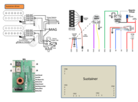 The idea is to have: - the sustainer driver and the Dimarzio pickups together in an Humbucker slot. The sustainer being used only as driver - both pickups (MK2 and DP 425) can be coiled tap via push pull on the tone control - magnetic volume has a push push to on/off the onboard effect (Modboard) via J3 and J4 - piezo volume has a push-push to switch from magnetic to piezo - the Modboard effect is controled via a 100k pot (J2) with push-pull for wah/Boost selection (J1) As I'm pretty new in modding and not far good in wiring, I would need your expert help on the whole wiring of that complex system, and additional though, namely: - I plan to power the midi XY screen thru the auxilliary power out of the phoni preamp and the Modboard from the sustainer board (as I understood the CN4/3 can be used for powering external active pickup or in my case the Modboard, right?). I can use two batteries then separately for the two "blocks". Is that a right choice or should I actually power the whole system with e.g. 2x9V battery in parallel? - the sustainer board and the piezo preamp are already making the whole system active/buffered, what is then better for wiring for the Modboard: true bypass or buffered? - The piezo preamp uses a 4 connector jack: how the sustainer and Modboard shall be connected then to be powered only when jack is connected? Sorry for so many questions but hope you guys can help...before I'm screwing up the whole thing with my new soldering iron ;-) Many thanks. Jean |
|


 #
#