|
|
Post by JohnH on Jan 19, 2007 20:19:26 GMT -5
Edit 11 October 2020 - see the end of this first post for an updated wiring diagram How many versions of a Jimmy Page mod do we need? Well when it comes to Jimmy Page and Les Pauls, I reckon too many is never enough:  The original version of the design is on the Gibson web site: www.gibson.com/Files/schematics/pagewiring.gifIt uses push/pull switches on all four volume and tone controls, to provide humbucker and single coil on each pickup, phase reverse and overall system series / parallel. It has some good things: - If done correctly, single coil combinations are hum-cancelling
- Out-of Phase single coil combos are also hum-cancelling
- No change to original appearance
And some not so great features: - The volume controls do not function consistently in series mode
- The 3-way pickup selector has to be in the correct position for series mode to work properly
- Loss of tone as volume is reduced
- Coils are shunted in single coil mode – possible tone loss
There’s been lots of versions posted on the net, see Borsanovas excellent recent one, which also adds local parallel wiring and bypass of the three way when switched to series mode:
Borsanova's scheme
But on the principle that more is more, here’s my version, which has some different features:
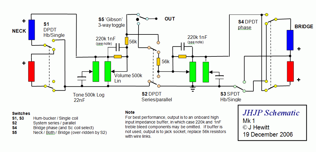
This has the same basic switching options as the Gibson, with added benefits:
As with Borsanovas, the series/parallel switch overrides the 3-way, so it does not matter where it is set when switching to series. I also have found this feature to be very useful on my LPmax design:
LPmax
For this current JP design, I kept with just the series/single local options, so each pup can be independently coil cut. I find the change from Bridge Hb to neck single to be very powerful, using just the 3-way toggle having preset the neck coil-cut. So I did not include local parallel options.
The volume controls work in both series and parallel modes for setting mixes between pups. The design works best with an on-board buffer, but with the treble bleed components shown, it also works fine as a passive design. I’ve tested this arrangement on the LPmax, so I know it works in both active and passive. The diagram shows both versions. see this thread for some buffer designs:
Buffers
The volume controls are forwards wired, which gives better control than reverse wiring. I found that with the values shown, the usual issue of one volume fading down both pups only occurs, in parallel combo mode only, when one pup volume is set below about 2. All the useful mixes are at higher levels, so this is not a problem in practice. However, with my favourite JFET buffer added, the 56k separating resistors can be introduced as shown, to stop this problem.
A wiring diagram will follow in due course.
EDIT 25/04/07.
Here is a wiring diagram for the JHJP. It was developed in collaboration with Runewalker, who provided the renderings of the parts (cool aren't they?)
Here it is with passive wiring:
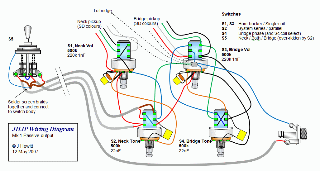
With four pots and four push/pull switches on the schematic, there is a free choice of which pot goes with which switch, and where they are placed. In fact, there are 576 ways to place them. They are all technically OK and valid.
Except perhaps, for the original Gibson way of laying out controls on an LP. Why did they put the neck controls nearest the bridge? Why put the bridge controls, which affect the higher sounds, at the low side? Why arrange the toggle switch, which selects front and back pups, to operate up and down?
We may never know, but based on the preferences of those who will be trying this design, the volume controls, which are the most often used, are put on top together with the coil-cut switches, and tone controls with series/parallel and phase switches are at the bottom. And bridge controls are nearest the bridge.
Now here is a second version wired to an active buffer, of the type I used on the LPMax.
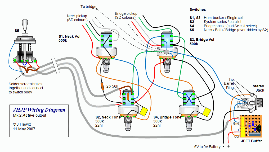
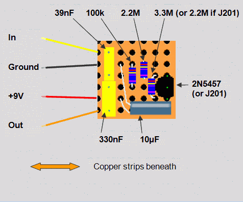
Layout for the buffer, on a piece of Veroboard (stripboard) is shown above, with values for using either a 2N5457 or J201 JFET.
So that should do it, except of course to build it. It hasnt been built yet, but, barring errors, I'm reasonably confident that all the parts of the design are OK since they have been tested on other guitars.
cheers
John
EDIT 25/04/2011:
Switch Settings
Here is a table of switch settings:

11th October 2020 - WiringHere is a new wring diagram, respecting the usual positions of LP control pots, and the most common placement of the switches for JP wiring: 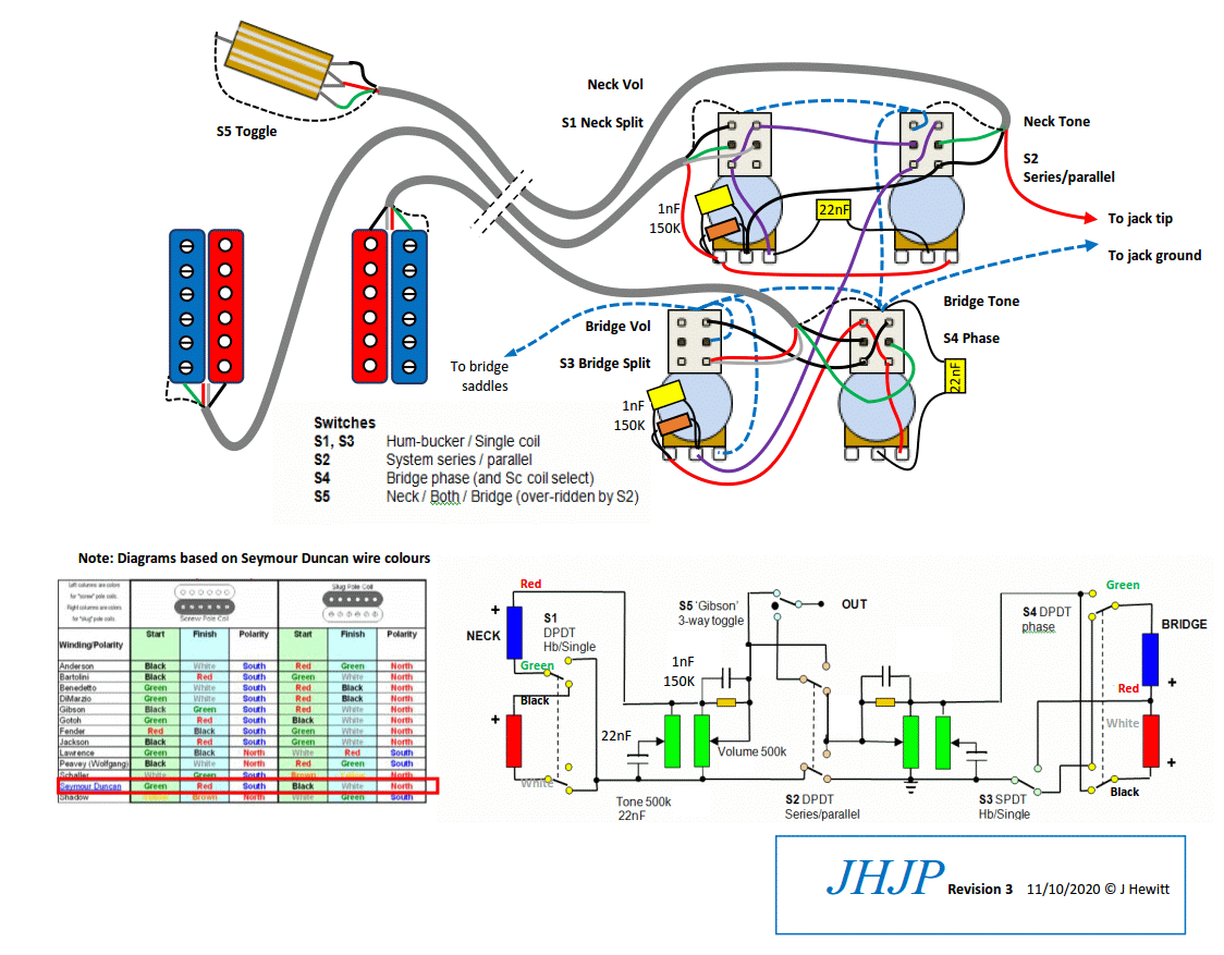 The schematic is essentially unchanged from the original passive version of this scheme, with SD colours and also update to treble bleed components based on later studies. I've also tried to capture the real orientations of pickups, polarities and wires, so hopefully it would be easy to configure in practice. The wires from the control cavity up to the main switch should be shielded, as they are in classic LP wiring. I show it here as a multicore screened cable, but it could also be divided into two or three separate cords.
|
|
|
|
Post by UnklMickey on Jan 19, 2007 22:22:25 GMT -5
How many versions of a Jimmy Page mod do we need?... , John...............................as long as it's the right one. ...........i wonder if this might be that one. |
|
|
|
Post by borsanova on Jan 20, 2007 13:43:36 GMT -5
Hello John, I like the way how you manage to draw your wiring schematic with a minimum of crossings and other complex structures that make mine so confusing  So here is my comment on your wiring: First let me say that I did my wiring in the first place not to add just another version to all the others, but to build my guitar without the faults of the Gibson edition and with the improvements that would suit me well. Before heating the iron I did my schematic by hand, a really awful drawing. My girlfriend tried several times to throw away the papers, because she thought it was just some scribbles to make my ball-point pen work.  I did the computer drawing only much later to document the benefits of my improvements. So first I want to defend the local parallel wiring option (dual sound) for the bridge pickup, which doesn't only shine in its own right (at least with a Duncan JB), but is also extremely useful in the series and broadbucker combinations. You wrote: "I find the change from Bridge Hb to neck single to be very powerful,..."This combination is in fact not excluded in my design. Just pull the neck tone control (with all others pushed) and you're there. It is however the only one that is not hum-cancelling with both pickups on. As regards the volume controls forward or backwards I can't tell much about the difference. My Epiphone was already backwards (though I had others which weren't), so I preserved it. In any case both of my volume controls work with series mode: the bridge volume is the master and the neck control serves to dial in and out as much of the neck as you like. Your design seems to be different though and it seems you don't have a master for series mode, but two independent volume controls like in parallel mode. As regards treble bleeds and buffers your competence is far beyond mine. I had treble bleeds installed in my guitar, but I omitted them in the schematic. I had cheap small yellow plastic blocks saying InQK100 or InOK100, but I wasn't too convinced about them and thus with the last modification I threw them out to verify the difference they made. Now I'm indeed missing a bit of trebles when rolling back the volume. Another impression is that the treble bleeds help to get smoother mixes in out-of-phase mode. That's why I'm thinking about putting them back in again, but this time a better variety. Which quality can you recommend? In a first moment I thought that the biggest downfall of your wiring was the fact that the signal passes first through the neck and then through the bridge. Usually this way you lose the biggest option of all: the broadbucker sound.  But with your design this doesn't seem to be the case, since both neck controls aren't grounded in their own right and in series mode return the signal to the bridge pickup. So I guess turning down your neck tone control could give you the broadened sound. In addition it seems you can play the same trick on the the bridge pickup (though this is actually little use soundwise). If you build your guitar, maybe you can check this (I'd be particularly curious about it, because I'd like to upgrade to broadbucker my Ibanez 345 which has the same neck-bridge serial wiring as your guitar. So your design could be a solution without a major rewiring which is extremely annoying in a semi-solid). So it seems your design has broadbucker as well. But then again you'd need dual sound (local parallel) for the bridge to get the most brilliant of power sounds...  For the theories of broadbucker wiring look here: guitarnuts2.proboards45.com/index.cgi?board=wiring&action=display&thread=1166627614 |
|
|
|
Post by JohnH on Jan 20, 2007 15:53:38 GMT -5
Borsanova - thanks very much for your comments. thats what this forum is all about. Let me also say that I felt slightly bad about posting a JP design right next to yours, but then they are different and I think we can all learn by comparing and discussing. Each has some unique features Hello John, I like the way how you manage to draw your wiring schematic with a minimum of crossings and other complex structures that make mine so confusing  Your diagram shows the wiring arrangements ready to build. My diagram so far is just a schematic, aimed at explaining how it works, but it would be hard to build from it. The wiring diagram will show some spagetti! Right on! the more the better, I say! Are you saying that there are some females who don't understand the importance of correct guitar wiring? No need to defend it - the local parallel is a very popular setting, bright and noise-free, and not available on standard JP designs. I'm coming to this design having had my LPmax for about a year. This has been my main guitar to pick up and play, and it has series/parallel wiring, and then instead of tone controls, it has 5-way rotaries for each pup, to give all local combos except parallel out-of-phase. I found, just for my own preference, that I nearly always use either Hb, or single coil. I combine them in series or parallel, in or out of phase. One thing that the LPmax and this new design will do is that all single coil combos, whether in or out of phase, are humcancelling. It does this by, when phase swapping the bridge, also automatically changing to the other bridge coil, so hum negation with a neck single is maintained. OK, thanks for explaining that Thats right I've done a few tests with this type of wiring, both with single pups and in a series chain as here, listening and also simulating using pSpice. The 1nF and 220k treble bleed values that I show are my best selection so far. but it can depend on the pickups, and the cable, and personally choice. However, my overall preference is to install an active buffer, which gets rid of the losses due to the cable, giving more top-end clarity in all settings, and making treble bleed redundant. Yes I think this will happen cheers John |
|
|
|
Post by borsanova on Jan 21, 2007 7:08:47 GMT -5
Borsanova - thanks very much for your comments. thats what this forum is all about. Let me also say that I felt slightly bad about posting a JP design right next to yours, but then they are different and I think we can all learn by comparing and discussing. No problem, that's how this forum works. One thing that the LPmax and this new design will do is that all single coil combos, whether in or out of phase, are humcancelling. It does this by, when phase swapping the bridge, also automatically changing to the other bridge coil, so hum negation with a neck single is maintained. This is the case on my design too, but I can't give the color codes because I used one Duncan and one DiMarzio and I had to try it out before I got it right. In the end I have only 7 non-hum-cancelling positions (out of 22) on my guitar, that is the three single coils and the four three-coils combos, while your guitar has 11 out of 21 that are not hum-cancelling. The 1nF and 220k treble bleed values that I show are my best selection so far. Got that, but I wanted some illustration on the best quality. I know that many swear upon orange drop caps, but they are extremely hard to find. So what would be your second best choice? Each has some unique features. I think the main novelty in your design is the use of the controls in serial mode. Your design preserves the same functionality of the parallel mode when both pickups are on. Any guitar player who has ever laid his hands on a Les Paul knows this feature and thus it may be an advantage, because you don't have to learn a new configuration. On the other hand I believe that those super distortion and broadbucker sounds will be used mostly when playing solo, and then a master volume might be useful. Soundwise I admit that your configuration has a little more flexibility, because it allows to dial out not only the neck, but also the bridge pickup. But since those super distortion sounds are already less brilliant, I don't think this adds too many useful choices to your sound spectrum. Maybe it can become a bit more interesting with serial out-of-phase combos. But in the end it seems a question of players preferences. In any case I've been thinking about how to implement this feature in my Les Paul and it's quite easy: simply cut the grounding connections of the bridge controls and connect them to the center lug of the series-switch. I don't think I'll build it, because I prefer the master volume, but I've adjusted my schematic and here it is (this preserves the local parallel wiring too): 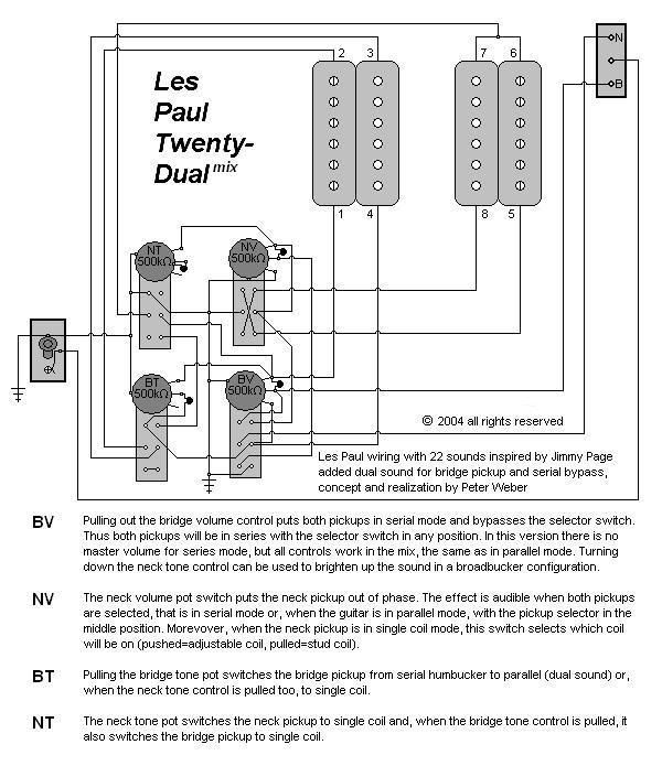 Version updated to the improvements suggested by John. |
|
|
|
Post by JohnH on Jan 22, 2007 6:13:31 GMT -5
I have no view on the best types capacitors, except an expectation that the types would not make much difference. I know that some folk think certain types are preferable. I use what I can get locally, which is yellow rectangular polyester for values 1nF to 470nF, and ceramic disk for less than 1nF.
John
|
|
|
|
Post by borsanova on Jan 22, 2007 18:59:33 GMT -5
Thanks for your advice, John. I've just updated my schematics to your suggestions.
|
|
|
|
Post by UnklMickey on Jan 23, 2007 12:46:41 GMT -5
John,
after evaluating this design, i've come to a few conclusions.
first, this is without a doubt the best-ever "stealth mod" for a 2-v, 2-t 'Paul.
you have assembled some great idea all under one roof, with each idea implemented in a location where it is most appropriate.
every selection is 100% clean in terms of shunts and hanging coils. hum-canceling is not only easy ........... its almost unavoidable.
starting from the far right, i recognize the Phase-switch -- HB/Split switch configuration. i used that in "the Big Ugly". i liked it there, and i like it here as well. that allows you to "automatically" maintain hum-canceling you chose to use it at the bridge, and it also allows your choice of bridge coils as singles. because of this, you also have a different bridge coil paired up the neck, when changing phase, in the bridge single mode. i would guess the coil farthest from the bridge would be a better choice when in-phase.
skipping across to the far left, your HB/Split completely disconnects one coil from the circuit, when in Split mode. This eliminates that coil from hanging from the middle of the circuit, when in System Series mode. (the Neck pickup gets placed on top, in Series mode.) although someone who plays at the higher frets would prefer that the Neck single be farther from the neck, the coil closer to the neck would be slightly more desireable when combined with the Out-of-Phase far closest to the bridge single, for most other players.
now, back across to the middle, and the Lead Switch Dark and Mean Switch. with the Seres/Parallel switch "wrapped around" the 3-way, you don't have the dead-spot common to most JP mods, when the 3-way is in the neck only position. this is a HUGE advantage, IMHO.
this is so much better, in so many ways, than the garden variety JP mod, it probably should be named the John Hewitt mod -- inspired by Jimmy Page.
now about push-pull positions. i haven't thought so much about which switch goes on which control, but about which function should be up, and which one down.
in general, i think the consensus is, down is "normal". following that theme:
full HB = down. Split = up.
in-phase = down. OoP = up.
system parallell = down. Dark and Mean = up.*
*i wonder if this one should actually be inverted.
if one does want that tone to be quickly accessed for a Lead, slapping the switch down, requires less thought and accuracy, than pulling it up.
the Bottom Line: this thing is a home-run in any park in the country.
..........or as they say in the rest of the world:
SCOOOOOOOOOOOOOOOOOOOOOOOOOORE!
|
|
|
|
Post by borsanova on Jan 24, 2007 9:54:57 GMT -5
system parallell = down. Dark and Mean = up.* *i wonder if this one should actually be inverted. if one does want that tone to be quickly accessed for a Lead, slapping the switch down, requires less thought and accuracy, than pulling it up. Hi mickey, I'd agree with this variation. But the problem is that most players start their thinking from the stock version of this guitar and they want to have the standard looks with the standard configuration. But if you look at the JP as an independent design, there is no reason why three switches should be making the sound thinner when pulled and one makes it thicker. Moreover I confirm that pulling out the series switch while preparing for a solo can become a quite annoying exercise. I have the alternative with the pulled bridge tone control and I can say that a slam on that one is much easier done. When I play songs like Weezer's "Island of the Sun" I start with both pickups in single coil mode for a clean rhythm guitar, at the second verse I slam down the neck control to get the neck HB-bridge dual sound combination and before the refrain I push the bridge tone control too (two humbuckers in parallel). For the solo I'd like to give it another boost with both humbuckers in series, but usually I stop here because I find it to complicated to get my nails under the knob of the volume control for pulling it out. This becomes even more difficult when I'm actually looking for the broadbucker sound and after pulling the bridge volume I have to complete another passage by turning down the neck tone control. On my guitar I already use the neck HB - bridge dual sound as the standard configuration from where to explore other realms. Thus the bridge tone control is always pulled when I pick it up and therefore having the bridge volume control pulled too wouldn't be a problem even esthetically. That's why I'd probably wire the series switch upside down, if I had to do it again. Thus all four switches would make the sound thicker when pushed and thinner when pulled. |
|
|
|
Post by JohnH on Jan 24, 2007 14:54:22 GMT -5
Unk - thanks for the comments. The design is a mix of various other more complex ones that we have discussed previously.
These designs can all be tweaked and personalised. For example, I'd have no hesitation in adding Borsanovas bridge-parallel addition if someone wanted it, since it is clever and adds extra sounds and hum cancelling combos, probably at the slight cost of a 'hang from mid'. BTW - the main reason I dont use local parallel so much is that with a buffer installed, it sounds very much like series Hb, at reduced volume.
As for switches - my choice would be to keep all down=stock, ie system parallel. I like to change from Bridge Hb to Neck single, and in that mode, the 3-way switch is all thats needed. This switch gets overridden in series mode.
John
|
|
|
|
Post by borsanova on Jan 24, 2007 17:57:18 GMT -5
I'd have no hesitation in adding Borsanovas bridge-parallel addition if someone wanted it, since it is clever and adds extra sounds and hum cancelling combos, probably at the slight cost of a 'hang from mid'. I don't know exactly the meaning of "hang from mid" and I had no knowledge of these wiring principles when I did my guitar, but now I've checked the schematic and I've found that the tapped coil on the bridge pickup is actually disconnected and hanging only from the ground (is this any bad?). The tapped neck coil is however shunted and with the basic switches at disposition I can see no way to eliminate this, due to the fact that this pickup has to work also in reverse for out-of-phase. But then, anyway, when I choose the neck single coil I guess it's not the brilliance I'm looking for... |
|
|
|
Post by UnklMickey on Jan 24, 2007 19:29:43 GMT -5
...I don't know exactly the meaning of "hang from mid" and I had no knowledge of these wiring principles when I did my guitar, but now I've checked the schematic and I've found that the tapped coil on the bridge pickup is actually disconnected and hanging only from the ground (is this any bad?).... hanging from mid, is my way of saying hanging from the mid-point of a series circuit. less of an issue than hanging from hot, but still something i avoid, when i can. leaving one end of an unused coil connected to ground is not a problem. cheers, umk |
|
|
|
Post by Runewalker on Jan 24, 2007 22:55:52 GMT -5
this is so much better, in so many ways, than the garden variety JP mod, it probably should be named the John Hewitt mod -- inspired by Jimmy Page.  |
|
|
|
Post by sumgai on Jan 24, 2007 23:04:16 GMT -5
Runewalker, Holy Moly, PaintShopMan, that's some artwork! Hey, for eye-candy like that, it's OK if you go AWOL once in awhile! But we'd really rather see you stick around.  sumgai |
|
|
|
Post by JohnH on Jan 25, 2007 7:10:08 GMT -5
RW - now thats what I'm talkin' about!
btw - to build this mod, you have to use traditional solder. None if this ROHS cr@p. No way you could play 'Houses of the Holy' or 'The Rover', through a guitar with no Led in it!
John
|
|
|
|
Post by JohnH on Apr 23, 2007 7:25:15 GMT -5
I have added wiring diagrams to the first post, to show active and passive wiring layouts.
John
|
|
|
|
Post by Happyguy on Jan 3, 2009 20:09:26 GMT -5
Hi, jumping in late on this.
So basically the resistors on the tone pots prevent the highs from being lost when volume is reduced? I have absolute faith that this works just as you say it does, i was just wondering why.
I have seen R C circuits in school, the resistance slows the "flow" so that the cap is charged slower, we charged it and then uncharged it into a resistor and then made graphs (coulombs/s) : does this have anything to do with this?
Isn't the pot a variable resistance? Is the resistor in series with pot and parallel with cap?
please keep in mind that i have only one electrical/magnetic physics class under my belt. No engineering skills lol.
Apart from that
Schematic -----> GET IN MY GUITAR!
|
|
|
|
Post by JohnH on Jan 3, 2009 20:59:42 GMT -5
Hi HG - thanks for reviving this one. If you are looking at the passive option for this design (without the buffer), then the resistors (220k) are part of the treble bleed circuit and are on the volume pots, in parallel with a small capacitor.
If you read up on 'treble bleed' on the net youll find out more. But in summary, when you turn down the volume, the signal is going through the volume pot instead of directly from the pickups. This ads to the output impedance, and the cord to the amp, acting as a capacitance, sucks away some of the treble. The treble bleed cap compensates by adding more treble, and the resistor helps to balance this effect, stopping too much treble being bled in proportion to the low signals.
Look, if that make no sense, just believe that it works!
The Active version does not need these resistors, but some different ones (56k) are shown, which help with mixing of parallel combinations . With the resistors, the common LP effect where one volume control at zero cuts out all sound is avoided, and parallel mixes are easier to set. They are not essential though, they can be just wire links.
If you go for this design - just be aware that I gratuitously moved the control positions around, rather than putting them in traditional (but illogical) LP positions. But in principle they can be reshuffled, with switches and pots in whichever of four positions is chosen by the builder.
cheers
John
|
|
|
|
Post by ChrisK on Jan 3, 2009 21:18:20 GMT -5
To match the toggle switch. To match the control layout. Actually, to match the natural motion of the strumming hand. You do now, it's hysterical in nature. Huh? I presume that the volume controls are in-line and closest to the strings. I presume that the tone controls are nearest the lower bout. Do you also reverse the 3-way switch? Does forward (neck-ward) now select the bridge, and aft-ward (bridge-ward) now select the neck? If so, call Gibson, you're their kind of thinker. ;D ;D ;D (Oh, this isn't one of those Oz things is it?)  |
|
|
|
Post by JohnH on Jan 3, 2009 22:52:23 GMT -5
Thats how my friend wanted it, so thats how I drew it. No need to presume, the diagram shows how I had it laid out. No, that would just be silly. But since I did that design, I have now got a real Gibbo LP in my possession, and so I have become atuned to its layout. So I think now that I'd keep with the 50+ years of precedent and keep the controls where they were first put. J |
|
|
|
Post by ChristoMephisto on Jan 8, 2009 18:02:06 GMT -5
I stumbled across a similar wiring from the main Guitarnuts site about using resistors to cure the parallel blues... Was wondering about this since you mention on the first page to use the resistors only with the buffer. I'm in the midst of wiring my Hagstrom Swede (Swedish LP) with only the series and neck OoP switches. Its vintage, so I didn't want to go popping the pups and ruin them. Thank you soo much for the great diagrams that made it easier to wire mine up. |
|
|
|
Post by JohnH on Jan 8, 2009 20:38:44 GMT -5
Hi Chris - thanks for your comment. I had not seen that early GN reference to using these series decoupling reistors. The reason I only suggested them for the buffered design is that you can in that case, introduce them and have no significant reduction on tone. But in a passive circuit, I found that they make a small but noticeable dulling of the edge, due to the capacitance of the cable. The tone at max volume is just a tad better without them. Its the same as when you turn the volume down slightly, and despite treble bleed etc, its still not quite so clear. On the other hand, the problem that the resistors address, which is one pickup volume being able to turn both off, IMO, is not a real problem. You can find all the mixes between parallel combinations in the upper regions of the volume controls, and by the time you turn one volume down to a point where it is undesirably affecting the other pup, its signal has long since faded audibly from the mix. So if you only wanted the sound of one pup, why not just select one pup?
So in summary, with a buffer, the series resistors are a freebie that helps with a not very significant probem, and dont do anything bad. Whereas in a passive design, they have a small detrimental affect and so are better omitted.
John
|
|
zoshquin
Rookie Solder Flinger

Posts: 3 
Likes: 0
|
Post by zoshquin on Mar 4, 2009 4:06:03 GMT -5
what did he mean by solder screen braids on the 3 way switch? I'm kinda new to this thing..  thanks in advanced |
|
zoshquin
Rookie Solder Flinger

Posts: 3 
Likes: 0
|
Post by zoshquin on Mar 4, 2009 5:28:03 GMT -5
can't i just leave the 3 way switch untouched?
|
|
|
|
Post by newey on Mar 4, 2009 6:23:08 GMT -5
Zoshquin-
Hello and welcome! What JohnH calls "screen braids" we would call a "braided shield". He suggests grounding them to the body of the three way switch to reduce noise.
You can try doing without it, but it may be noisier without doing so.
|
|
zoshquin
Rookie Solder Flinger

Posts: 3 
Likes: 0
|
Post by zoshquin on Mar 4, 2009 6:39:33 GMT -5
Hmm ok I'll try without doing it cause my wire doesn't have it..  thanks for the reply, now I can rewire.. hehe |
|
|
|
Post by JohnH on Mar 5, 2009 21:28:25 GMT -5
Hi Z - thanks for the interest in this scheme.
You can make it work without shielded/screened wire, but Id really recomend using it. The lengths of wire up and down from switch to control cavity could pick up some noise that you dont need. Its not special stuff, any screened audio-type wire such as used to connect audio components is fine, as is the wire used on guitar cords
Also, we can now report that this design has been built sucessfully by Happyguy!
good luck
John
|
|
Blue~Slim
Rookie Solder Flinger

Posts: 2
Likes: 0
|
Post by Blue~Slim on Apr 9, 2011 9:56:45 GMT -5
I know this tread is old but hopefully this will be read. I just installed John H's passive schematic in my Gibby Les Paul Traditional Pro - Wine Red....I love this guitar and now, love it even more which I didnt think was even possible!!
After installing two other schematics that i chose for no particular reason, they didnt turn out so great but got some practice under my belt. I finally slowed down and did more thorough research into correct soldering materials, methods, shielding, etc. I ordered all the right stuff i needed this time and then just had to decide on which schematic to use. I was determined to make this a "third times a charm" situation instead of a "three strikes your out". So it all came down to two of the best schematics out there...Borsanova's Twenty "Dual" Mix and John's JHJP Schematic. I chose John's because it looked like what I wanted. I am new to all this so I used my common sense and what i learned so far to apply his wiring with shielding. Got it all together and it worked perfectly with no noise the first time!
One quick word of advice for anyone soldering for the first time. Do yourself a favor and read up on the correct meathods. The biggest thing that i didnt do the first time was tin the tip of the iron. Such a simple step saves tons of aggravation. Also take your time and order the right wiring, use the right solder (per jonesy 60/40 rosin core .062 dia.) Infact tonemojo.com has a lot of wiring tips. Anyway I just wanted to throw that out there for other newbs.... i was just there.
I have two questions for whomever might know:
1. I am waiting for my treble bleed pieces to come in the mail so right now i just have a jumoer where the treble bleed circuit will go. What does this effect on tone etc other than not having the treble bleed benefit. i will install it when it comes but just curious.
2. Is there a written list of all 21 different tones listing the switch settings for John H's schematic? Also it would be really cool if the list showed and "broadbucker" type settings as well. I think i understand all the settings but it would be nice to have a list.
Overall could not be happier! Thanks John H. for an incredible job on your diagram...oh and the person who rendered it!! much easier to follow!
|
|
|
|
Post by JohnH on Apr 12, 2011 15:28:31 GMT -5
Hi blueslim and welcome to GN2!
Thankyou very much for your post, and well done indeed for getting it together in one go. +1 to you right there.
The treble bleed circuits have no effect at full volume, but as you turn down, it stops the tone getting a bit duller and losing its edge. Most guitars dont have this, and you can try with and without, but Id recommend having them, particularly in this guitar with its series wiring. Since doing that design, I worked out that a slightly better value for the treble bleed resistor is 150k instead of 220k, but 220k is good too.
I'll try to make a table of settings and post soon
cheers
John
|
|
Blue~Slim
Rookie Solder Flinger

Posts: 2
Likes: 0
|
Post by Blue~Slim on Apr 24, 2011 8:30:12 GMT -5
Hello again John and thanks for your reply and kind words. I did install my treble bleed and it made quite a difference. I couldn't be happier with my LP now. ;D
Not to bug you but I am still looking forward to a settings list for your great schematic. I particularly wanted to know exactly how to get the broadbucker sound which if I read the posts between you and barsanova does exist with your wiring. You just went about it a little different than he did.
Thanks again for your help.
|
|




 I did the computer drawing only much later to document the benefits of my improvements.
 But with your design this doesn't seem to be the case, since both neck controls aren't grounded in their own right and in series mode return the signal to the bridge pickup. So I guess turning down your neck tone control could give you the broadened sound. In addition it seems you can play the same trick on the the bridge pickup (though this is actually little use soundwise). If you build your guitar, maybe you can check this (I'd be particularly curious about it, because I'd like to upgrade to broadbucker my Ibanez 345 which has the same neck-bridge serial wiring as your guitar. So your design could be a solution without a major rewiring which is extremely annoying in a semi-solid).


