|
|
Post by blackhillsman on Jun 16, 2010 1:54:56 GMT -5
Hello to All Nutz, I'm new here, you guys have a nice house....lots of good books on the shelves to keep me reading and learning for a long time. My questions realte to wiring a Bass VI - I build relics part time and play Bass VI's in my band, and I want to get this latest build really thumping sound-wise. Firstly are there any of y'all out there who know the type of wiring in an original Bass VI? ie are the p/ups wired in series or parallel? Here's the stock w.d. link: zeus.lunarpages.com/~jimshi2/wiringdiagrams/bass6.jpg For example I am using the 4 way switch (post 1962 model) with the capacitor for the "strangle switch" removed from the picture as I find it un-useful. What I have p/up-wise are 3 hand-wounds for the instrument from Peter at the Pickup Wiz in Canada, and the middle p/up is RWRP...I know from reading on John's Guitarnuts.com site that p/ups in series give us more grunt/output... I guess I want to be able to have tough or full output with any 2 p/up selections or all 3... Any help/suggestions/mods to the stock wiring would be most appreciated! Thank you all. |
|
|
|
Post by newey on Jun 16, 2010 5:56:27 GMT -5
Blackhillsman-
Hello and Welcome!
Your pickups, if wired as per the diagram, are in parallel. Any number of schemes are available to wire them in series, and to be able to switch back and forth between the 2 as well.
The diagram you posted is pretty stylized, and doesn't give us much information. For example, you mention a capacitor you removed from a "strangle switch", but I don't see any capacitors on the diagram. And it's not clear exactly what the switches are doing- I assume the first 3 are on/off for each pickup? With the 4th being the strangle, minus capacitor?.
One of the first questions you need to answer for yourself is whether you are willing to alter the stock appearance with the addition of more switching or not. If not, your options are more limited.
If the slide switches are just on/off (as I'm assuming) then replacement with more capable switches (3 position ones) could be used to do series/parallel wiring, assuming you can find matching-sized switches.
|
|
|
|
Post by blackhillsman on Jun 16, 2010 7:17:22 GMT -5
Thank you Newey,
Yes the diagram is just that - all 4 switches are on/off with the fourth (closest to bridge ) having the bass cut or strangle cap (which I deleted in my current VI). I am leaning towards not having to add any additional switches in order to keep it simple - and wiring the thing so that they run in series (having the options of soloing each pickup or the choice of neck and mid. mid and bridge, neck and bridge, or all 3 together) - could you point me to a diagram that can pull that off - or come close? I am having to deal with delivering the main vocal and playing the VI as a baritone without a bass player so I need to make my choices and settings easy and simple...ha ha!
Thank you for your interest and input!
|
|
|
|
Post by newey on Jun 16, 2010 11:17:01 GMT -5
OK, we need to take a closer look at those slide switches you have. Fender made several different types, as used in various Mustangs, Jaguars, etc. A simple On/Off switch won't work for series wiring, as disconnecting one pickup will disconnect them all. Remember the old-style Xmas tree lights, where if one bulb failed, the whole string went out? Same thing here. More robust switching will be needed if those are simple on/off switches. Take a look to see how many lugs are on each one. Now, we recently had several versions of the "Brian May Switching" floating around here. As originally wired, those guitars used slide switches for on/off, and also for phasing. The guitar has 3 single coils, originally wired in series, just as you want, with on/off switches for each. That diagram could be a starting point for your wiring. The thread on the BM is here, the first diagram there (before we started discussing modifying it) is the stock wiring: guitarnuts2.proboards.com/index.cgi?board=wiring&action=display&thread=4641&page=1Notice that the slide switches for the on/off are DPDT switches (6 lugs apiece). If your existing switches are like that, you're good to go. However, if yours have fewer lugs, new switches will be needed. |
|
|
|
Post by sumgai on Jun 16, 2010 12:47:23 GMT -5
Or we could just take a gander at this little puppy: 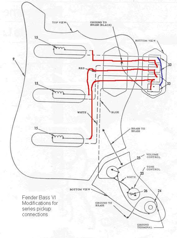 .... and have a field day with Ye Olde Soldering Iron. ;D See notes further on down, please. (Sorry, I had this done hours ago, but I couldn't convince Photobucket to recognize my login credentials. Finally resorted to resetting my password, and that solved it.) ~!~!~!~!~!~!~!~ bhman, Hi, and  to the NutzHouse! Fender's depiction is very clear, and is correct - there are only two solder lugs present. This is another one of those times where Leo reached "across the aisle" to the Amp Parts bins, and snagged a handful of slide switches that he used in so many of his amplifier models for the "Bright" function. I tried to keep it simple, hoping that you'd need only to move some few wires the shortest distance necessary. Above, Red represents "hot" lines and Blue represents the single ground line. Also, I let the the fourth switch remain unused, as you didn't ask for anything to be done with that.... at least not at this time.  All you need to do is disconnect the three wires that are grounded to the brass plate, and run them over to the switches as shown. (Likely you'll have to extend those wires with short lengths, that's OK.) You'll also note that I "used white-out" where you need to remove some short jumper wires normally found on the switches. When it's all done, your work should look like my diagram above. (And note that one of my red leads runs directly between two arrows, with a note above that says "ground to brass" - that's a note that I didn't erase, because the original wire going to ground should remain there. The red lead runs over that, and obviously does not connect to it in any way.) While it may look like I've reversed the phase of the pickups - the former ground lead became the hot lead - in fact, the same is true for all three pickups, so the net effect is 'no difference'. HTH sumgai |
|
|
|
Post by newey on Jun 16, 2010 22:05:55 GMT -5
Never fails. Every time I say something can't be done with a certain switch, some guy comes along to prove me wrong! ;D ;D
BHM-
SG's scheme will work as advertised. I wondered only if you might get an occasional "pop" upon switching some combos, but that may not be the case.
|
|
|
|
Post by sumgai on Jun 17, 2010 13:44:01 GMT -5
newey, Pops usually occur due to a circuit changing state between fully open and something else. State changes between dead shorts and some value (besides fully open) usually don't pop. But of course, that's only a rule of thumb, and not cast in stone. I think wolf (aka Mr. Series-is-good-for-you) will corroborate this. HTH sumgai |
|
chase
Apprentice Shielder

Posts: 30
Likes: 0
|
Post by chase on Jun 24, 2010 0:41:57 GMT -5
Bass VI is wired in parallel, as newey said. I have a VI guitar as well (a Schecter) which I recently had rewired to give me all the parallel combos and three series combos. You can follow the wiring diagram discussion here and see the end result here. I think if you hunt around you may also find some diagrams which would allow you to make the strangle switch into a series-parallel switch, which would look vintage-correct but give you lots of options. sumgai's solution is very clever though and has the advantage of using the existing switches. |
|
|
|
Post by sumgai on Jun 24, 2010 3:47:14 GMT -5
......
The diagram you posted is pretty stylized, and doesn't give us much information. For example, you mention a capacitor you removed from a "strangle switch", but I don't see any capacitors on the diagram. I forgot to post this in my previous epistle.... newey, look at Part #31 - it points to a schematic symbol for a cap, not the actual physical item. Strange how they did this, I know. But back then, who was bird-dogging anybody in that business?  HTH sumgai p.s. Thanks, Charles. |
|
mercu80
Rookie Solder Flinger

Posts: 3 
Likes: 0
|
Post by mercu80 on Oct 15, 2014 0:07:56 GMT -5
HI! I would like to modify my Squier Bass VI..removing the strangle/cut switch..and using it as a series/parallel switch.
Anyone has a valid diagram my tech could work with?
I would like not to add new switches and made the mod as this:
"- if the former strangle-switch is down, you get all the old pickup-choices, no change here.
- with the (now) series-switch up, you got 3 veeery useful new sounds:
1) neck+middle switch up: neck+middle in series (fat bassy tone, more volume+basses)
2) middle+bridge switch up: middle+bridge in series (lowmid-ish growl, nice with distortion)
3) all 4 switches up: now thats the most interesting one. neck+bridge are parallel and then in series with the bridge!! this produces a sound that has both the fatness of the 1) setting but with more treble and transparancy to it. cuts through very well.
in series mode, only one pickup switch up means that there is no signal."
thank you in advance to anyone!
|
|
|
|
Post by sumgai on Oct 15, 2014 1:13:39 GMT -5
mercu80, Hi, and welcome to the NutzHouse!  .... neck+bridge are parallel and then in series with the bridge!! this produces: .... no sound! At least, that's what happens when you short the bridge leads, which in turn effectively shorts the whole output. Or did you perhaps mean that the combo should be (N+B)*M (Neck in parallel with Bridge, both of them in series with Middle)? Tonally, that would work, and sound pretty good. More in a moment, but first: Well, what you're asking for now is well beyond the highly limited capabilities of any two-position slide swith known to man. There are four-pole versions available, but they're physically bigger - I doubt they'd fit directly into your current plate. But even before that, we need to address your desire to, in exacting detail, switch literally 5 of the 6 available pickup wires, and no slide switch is gonna allow you that kind of control. (Note: why 5 wires, and not 4? Because you want the scenario where only one switch up produces no sound. That's an extra pole, working in tandem with an extra pole on either the Bridge or the Neck switch.) Fortunately, while in series mode, as shown above, only one switch up is still gonna turn on a pickup, and that's more or less what a player expects - turn it on, it should deliver sound. And let me take a WAG here, but if you're wanting an "Off" position, then look no further than all three switches down.... all three pickups are shorted, and so is the output - the hot lead is running direct to ground, thus silencing your axe. But what you want is doable, if you're willing to go a tiny bit Nutz. The hidden trick, to stay with the stock appearance, would be to replace the tone control with a 6 pole, two throw rotary switch. That will allow all of the switching control you've expressed a desire for, plus, you can leave the 4th (strangle) switch in place, and either disconnect it, or use it for phase reversal (OoP). Oh, and if you still want a tone control, then just snag a Jazz Bass dual concentric pot, with knobs - that should take care of it! Good luck, and HTH! sumgai |
|
mercu80
Rookie Solder Flinger
Posts: 3
Likes: 0
|
Post by mercu80 on Oct 15, 2014 13:05:15 GMT -5
Hi Sumgai...thank you for your time..well I am a bit confused... I am not a skilled electrician... but in other places I found this diagram...gave it to my tech... and it is not working as expected... DO you think this is wrong..? or maybe he made some errors... again... I am not very well ready to read it...but other says it should work... thank you again...  |
|
|
|
Post by reTrEaD on Oct 15, 2014 20:31:59 GMT -5
Not sure who other is, but they're only partially correct. In the parallel mode, this should work as expected. In the series mode, it will be rather fussy.
- If only one pickup is selected in the series mode, there will be no sound.
- If only the bridge and neck are selected in the series mode, there will be no sound.
- If the middle pickup and at least one other pickup is selected in the series mode, there will be sound.
|
|
|
|
Post by sumgai on Oct 15, 2014 23:56:37 GMT -5
merc,
Well, someone has beaten me at my own game - thinking outside of the box. Well done, indeed. But....
I have to say, this doesn't fit my (nor I suspect, most folks') definition of switching between parallel and series combinations. What you've got is a partial set of combos, specifically designed to deliver only a small subset of possibilities. Had I read into your first post - "This is what a I want, and all that I want", I might have taken a different tack. I suspect other responding members might also have taken that different tack, but I'm not speaking for them, only myself.
Nonetheless, if the switches are good, and the ability of your tech to follow a diagram is good (and his ability to solder properly), then this circuit should work as you intend.
HTH
sumgai
|
|
|
|
Post by newey on Oct 16, 2014 5:21:41 GMT -5
Ask 3 different Nutz™, get 3 different answers!
Actual RT and sg are saying the same thing. Rt says it's a bit wonky in series mode, and he's right. SG points out that the combinations you said you wanted are wonky to begin with. He, too, is right, in that sense, it's a weird setup.
But I'm afraid I'm going to disagree with both of them. I see everything working as set out in the first post, except for this:
I'm not seeing that with all 4 switches up. What I see is no parallel combinations at all in that setting. I see the Br in series with the Mid (B x M). However, the Br Ground wire is grounded, and the bridge "hot" wire then connects to the neck "hot" wire, and is then connected to ground through the neck pickup? (not sure that's right, but that's what I'm seeing).
If so, I don't know what you get, but my thinking is that you get either no sound at all, or you get the middle pickup by itself. Either way, it's not what was intended.
But I think we're going about this backwards. Merc, you said:
If you have already wired the guitar up with this scheme and it is not working as expected, which settings are not working? Please verify which coils are active in each of the settings of the various switches, by tapping the coils with a metallic object for each switch setting. In this way, we can better "zero in" on the problem and see whether it is a problem with the diagram, or with the execution of the diagram.
|
|
|
|
Post by sumgai on Oct 16, 2014 11:27:54 GMT -5
newey, As pointed out earlier in this thread, bh'man might've made a mistake in his nomenclature, during his first post. I surmised that he intended to say "Neck and Bridge in parallel, all that in series with Middle", whereas he ended with the word 'Bridge'. I believe that he's not corrected me, so let's chalk it up to a case of 'fat fingers' or somesuch, and go with (B+N)*M, OK? In that case, follow the diagram again. Middle's hot is hanging, so tracing out Mid's ground shows... no connection when selected by itself - it must have either Bridge or Neck to complete the circuit to ground. Bridge and Neck are both still in parallel, so it follows that selecting both at the same time, meaning when all four switches are up together, you get the desired combo. As a one-trick-pony, not a bad way to go - certainly it fulfills the stealth requirement, whiile yielding unexpected tones. My only "gripe" would be that it doesn't have B*N, a commonly used 'power' tonality. Indeed, using B+N, and then selecting Series shuts off all sound - Middle is required for any sound at all in the Series position. All in all, a good way to expand the tonal pallette, even if a bit limited. The big payoff - no cash outlay for parts! Can't say anything bad about that! sumgai |
|
|
|
Post by newey on Oct 16, 2014 20:32:36 GMT -5
Guess I'll have to do so, I wasn't seeing it this morning. And it's too late this evening to wrap my mind around it again . . .  |
|
mercu80
Rookie Solder Flinger
Posts: 3
Likes: 0
|
Post by mercu80 on Oct 17, 2014 5:48:57 GMT -5
newey, As pointed out earlier in this thread, bh'man might've made a mistake in his nomenclature, during his first post. I surmised that he intended to say "Neck and Bridge in parallel, all that in series with Middle", whereas he ended with the word 'Bridge'. I believe that he's not corrected me, so let's chalk it up to a case of 'fat fingers' or somesuch, and go with (B+N)*M, OK? In that case, follow the diagram again. Middle's hot is hanging, so tracing out Mid's ground shows... no connection when selected by itself - it must have either Bridge or Neck to complete the circuit to ground. Bridge and Neck are both still in parallel, so it follows that selecting both at the same time, meaning when all four switches are up together, you get the desired combo. As a one-trick-pony, not a bad way to go - certainly it fulfills the stealth requirement, whiile yielding unexpected tones. My only "gripe" would be that it doesn't have B*N, a commonly used 'power' tonality. Indeed, using B+N, and then selecting Series shuts off all sound - Middle is required for any sound at all in the Series position. All in all, a good way to expand the tonal pallette, even if a bit limited. The big payoff - no cash outlay for parts! Can't say anything bad about that! sumgai Yep.. Sumgai.. I made an error in my first post.. It is as you said ... (B+N)*M... My fat fingers!!  I imagine this is a pretty limited set... But always better than the stock.. And above all far better that the New Fender Pawn shop bass VI with 5way selector.. At this point I think my tech made something wrong... When series is active only middle is active..  |
|
|
|
Post by sumgai on Oct 17, 2014 15:05:21 GMT -5
bhman, Recall what we said earlier - in order for anything to sound out in the Series position, at least two pickups must be switched on. By extension, Middle's ground (blue) wire doesn't go anywhere unless one of the other two are also on... only in that way can the blue (ground) wire be connected, thus completing the circuit. For you to say "only the mid is active" tells me that something is seriously wrong, i.e. a complete screw-up in the wiring department. I can't begin to tell you where the error might lay, numerous possibilities aboond*. If it were me, I'd remove the switch-mounting plate and double-check the tech's work for myself. Be careful as you go along, and perhaps make a checkmark (on a paper diagram) against each wire as you trace it out with your hands/eyes. I'll bet you can find the error pretty quickly that way. BTW, have you figured out yet that the Neck and Bridge ground (blue) wires don't need to be switched? That's right, they're always going to ground, whether it's in Series or Parallel, so you might as well just solder them straight to the common ground point (usually the back of a pot). That reduces the number of possible failure points, whether it be switch contacts or poor solder joints. HTH sumgai * That spelling is a small courtesy towards our dearly departed member, ChrisK. He liked to sound as if he were German, on occasion, hence his "off-key" spelling. Even after 4½ years, we still miss him. |
|
|
|
Post by JohnH on Oct 17, 2014 15:21:29 GMT -5
Im not sure if its been pointed out yet, but if you are serious about a fully functional set-up with three on/off switches and a series parallel switch, the S/P switch needs to have more poles than two. It needs four in fact. Then you can have an on/off for each pickup, and whatever you switch on is either in series or parallel (or just a single in you only switch on one), and there need be no dead spots except the expected 'all off' setting. Slide switches can still be used for the on/off controls, but the S/P switch tends to be a toggle to get enough poles: This is one way, and ignore the three phase switches, for a Brian may type of system: three pickups with series/parallel - Red SpecialThese days, we can get a Fender S1 switch which is a four pole switch built into a pot, as used on American Deleuxe Fenders. One of those plus three sliders would also do it. I realize that this thread is all about using existing switch configurations, and with the two poles switch for S/P, something has to give, hence the discussion here. There are likely o be other ways to cut this cloth. I quite like this one from newey, which was also about the Brian May guitar, using a two pole switch to add some parallel tones to a normally series set up: Red Special with parallel tones |
|
|
|
Post by ChristoMephisto on Oct 18, 2014 9:02:27 GMT -5
I have my Bass VI wired for series parallel and have the strangle switch still present.
But I'm using dpdt center off switches to get it. Still get all the parallel combos, plus middle in series with bridge and or neck. Also two pups in series with one parallel.
My strangle switch has two options. The stock .0033 and two .0033 for less bass cut.
I can post it later when I get home if anyone is interested.
|
|
|
|
Post by sumgai on Oct 18, 2014 10:47:57 GMT -5
Christo,
Nice to see your "rockin' cat" avatar again! You need to pop in more often, like some of the other long-time members I could name (but won't, out of courtesy of course).
I for one would like to see that diagram of yours, so please, go ahead and post it.
sumgai
|
|
|
|
Post by ChristoMephisto on Oct 18, 2014 12:01:53 GMT -5
Here's my s/p wiring for my Bass VI. You will need to use dpdt center off for the neck and bridge pups and for the strangle switch if you want two strangle modes. The middle switch is a plain dpdt switch. The hard part is finding the two different switches with the switch tip the same height. Originally it started off as two dpdt switches that put the neck n middle pups in series and parallel. It's an old wiring mod from this forum but can't find where I got it. I added the bridge in the same way the neck switches in and out with the middle pup. With the switches up, you get all seven standard parallel options. With the middle switch and another pup switch down is series. You can also have both neck n bridge parallel into middle. When the switches are in the middle position, that pup is off.  If you use a plain dpdt switch for the middle pup instead of a center off type, there are less dead spots. For the two tone strangle switch, both caps are .0033uf. Down is bypass, middle postion is the stock .0033 and up is both caps parallel for .0066uf. You could probably use any cap values to taste. The .0066 strangle sounds good for taking a bit of mud out of series and add a low end thump I find. |
|
sheutran
Rookie Solder Flinger
Posts: 8
Likes: 0
|
Post by sheutran on Jun 28, 2016 14:27:01 GMT -5
Hello everyone,
May I dig out this topic for newcomers like me ??
So, I followed the series/parallel switch mod diagram provided by Mercu80 and it just happens that I have the same problem as he: when switched to series mode, only the Middle pickup is actually to be heard.
So, I wondered if after all this time, none has solved this issue?
A weird thing is that, if we follow the diagram, when only Middle bridge switch is active, this pickup should be grounded to nowhere ! Or at least, to no ground output !!
Have some of you already faced that enigma ?? I start to question the black leads screws at the bottom of each pickup cavity, it should ground only the different plates etc... not the pickup coil on itself ......
Greetings.
|
|
|
|
Post by newey on Jun 28, 2016 22:43:35 GMT -5
Sheutran-
Hello and Welcome to G-Nutz2!
No problem resurrecting an old topic, especially if you're having the same problem. We never heard back from Mercu80, and so, no solution to the problem. In particular, he never responded to my questions. I asked him to particularly describe which coils he was getting in which switch positions. I'll ask you the same: Do you mean that you get only the middle pickup alone when the series/parallel switch is set to "series", regardless of the positions of the other switches?
As RT noted above, this is a particularly wonky way of wiring this, but I can't see how "middle only" would be the result.
Therefore, please describe what you get in the various switch positions, and please use the screwdriver test to determine which coils are indeed active.
I don't know what you mean by "When only middle bridge switch is active".
and I also don't get what you mean by:
We may be having some language/translation problems here.
|
|
|
|
Post by newey on Jun 28, 2016 23:02:00 GMT -5
Just so we're clear on this, with the series/parallel switch set to "series", you should get no sound whatsoever unless the middle pickup switch is set to "on". If the middle pickup is off, no other combinations will give any sounds in series mode.
If the middle pickup is set to "on" and the series/parallel switch is set to "series", then the following pickup combinations should result:
1) If the middle pickup and neck are both "on", you should have neck and middle pickups in series (i.e., N X M).
2) If the middle pickup and the bridge are both "on", you should get bridge and middle in series (i.e., B X M),
3) If the neck, middle and bridge are all "on", you should get the neck and bridge in parallel, with both in series with the mid pickup (i.e., (N + B) X M).
Thus, if you are truly just getting the middle alone in the series setting, there is no obvious simple error that could account for this, there would have to be a couple of separate problems occurring simultaneously.
|
|
sheutran
Rookie Solder Flinger
Posts: 8
Likes: 0
|
Post by sheutran on Jun 29, 2016 5:10:19 GMT -5
Hello ! First of all, thanks for being so much active on this forum, I'm very pleased to share infos about the Bass Vi ! So, to answer your first question, yes this is exactly what you suggest: I get only the middle pickup alone when the series/parallel switch is set to "series", regardless of the positions of the other switches. And moreover, when series mode is (supposed to be) on, I get no sound if the middle pickup is turned off. I tried playing in different ranges and at the same time turning the two other pickups (i.e neck, and bridge) either on or off, it makes no differences to the sound. I don't have a screwdriver that can test the signal, but I previously spotted with a beeping multimeter which cables were hot and ground point for the 3 pickup :-) and I don't have problem when running pickup in parallel. So before I desoldered all wires and resoldered these following the diagram, I was pretty confident about which cables I had to swap, and after, I also tested again the signal by putting probes of my multimeter a bit everywhere throughout the 4 switches connections, and nothing seemed irregular. So in a nutshell, it's as if my multimeter agreed with the diagram provided, but the laws of nature interferred with the theory ! haha. And, one last thing, when I spoke of the black lead screwed at the bottom of a pickup cavity, I just mention a ground cable that is connecting every metal pieces around any pickup to the main ground, has anyone ever removed these ground cables without having any buzz Thanks in advance for your concern ! Cheers. |
|
|
|
Post by newey on Jun 29, 2016 5:53:54 GMT -5
OK, this is for shielding purposes, and doesn't have anything to do with your problem. Disconnecting these could increase your noise level, or maybe not, but it's a bit of a risk to do so. It might be dead quiet in your house, but noisy in some other environment, like a bar where you would be playing, for example.
As I described above, this is exactly as it should be with this diagram- and it is the reason sumgai, reTrEaD and I all wondered why anyone would want to do this. It has the advantage of retaining the stock switches, but a lot of wonky dead settings are the price one pays for not having to buy different switches. Cheshire Cat's scheme above avoids the dead spots, and seems a more useful wiring to me, but it does require purchasing new switches.
At any rate, if this is the scheme you want, we can try to see why it doesn't work. It is good that you have a multimeter. You can do the screwdriver test (tapping each pickup to see which ones are active) with any (magnetic) metal object, it doesn't have to be a screwdriver. You can also test with your multimeter: Plug in a guitar cable at the guitar end (only), and apply the leads of your meter to the tip and sleeve, respectively, of the cable's plug. Set your meter to read resistance, and set it to 20K Ohms range if it is not an auto-ranging type of meter. Turn the V and T knobs to "10", and take resistance readings in all series positions. If only the middle pickup is truly active, your readings should be the same in all positions, probably around 7KΩ or so.
We could tell more if you had taken the readings of each of the pickups before wiring them into the circuit, but I suspect you did not do this previously. No reason to dewire it now just for that.
I don't have any easy answers here, so let's let some others weigh in on this problem. I may be missing something obvious.
|
|
sheutran
Rookie Solder Flinger
Posts: 8
Likes: 0
|
Post by sheutran on Jun 29, 2016 7:39:07 GMT -5
Thank you for your advice,
I'm gonna take another serie of testing with my multimeter as soon as I can and then I'll prompt the results !
I wish I had a new inspiration after this done ! haha thanks for all. Cheers.
|
|
sheutran
Rookie Solder Flinger
Posts: 8
Likes: 0
|
Post by sheutran on Jun 30, 2016 5:47:35 GMT -5
Hello again,
So here I am with my ohmeter, and my probes touching the TS jack by its end, and what I read is pretty relevant !
I get around 6kOhms for neck and middle, individually, and 12K for the bridge.
So far, I have to admit something, I just tweaked the diagram provided to engage both Bridge and Neck pickup in series, instead of Middle + Neck in serie. That only means I swapped the wiring diagram between middle pickup and bridge pickup to achieve mine ! But, hehe guess what pickup only works then: my bridge pickup yes!
This is why I assumed I had the same symptom as previously reported by mercu80, anyway, here comes the second part:
When in parrallel, the impedance is divided each time an additional pickup is switched to active, but when in the so supposed "series mode", only a 12K is read, which correspond to the Bridge impedance only !
To bring more infos, I noticed two things, the 1st is I measured the impedance of Neck and Middle when all pickup were on, and series mode active. So it give a 0.20K value per pickup, and the bridge is still 12K. Would it confirm there is a leak anywhere ?
In addition, I noticed a weird thing concerning the shield connection between metal parts around each pickup. I don't know if anyone experienced this before but it appears that, after my modification, I can only hear a beeeeeep contact when Bridge pickup is switched On, and in parrallel mode ...
Incredible so far because I can only hear this singular pickup in Series mode !! (I ran the screwdriver test yes, sorry but last time I said I didn't have a screwdriver, I don't know why but I thought of a electronic screwdriver that serves voltage tests !! I got complicated for nothing haha)
So yes there may be dead spot in that config, but I wonder if the 3 black leads that are supposed to come from the neg. tip of each single coil is really running directly from these or if it has hidden contacts with any other throughout the body of the guitar ......
This is not the end of it but, I start throwing a eye upon Christo's diagram where 3 pos. switches are used to make a custom parrallel/series switch plate ! :-)
|
|


