|
|
Post by newey on Jan 1, 2022 16:46:28 GMT -5
i have a jumper on my 3way that i use for series parallel split coil. am i able to remove that jumper and replace with a cap and accomplish the jumpers job and get better results thanks to cap or does the cap need be placed esle where? has me thinking if im able to use the cap as a jumper to get split coil and it aid tone can i hook leads to 3way and then clip different caps to find best value for my humbuckeI'd have to go back to see the diagram. As for testing for the best cap value, all that can be done external to the guitar, once we see exactly what you're doing with the cap. It is probably best to go back to your original thread where we worked out the diagram and repost this question so we can see what was done there. |
|
|
|
Post by newey on Jan 1, 2022 8:43:54 GMT -5
patricknuts:
Hello and Welcome to G-Nutz2!Your last post is indecipherable to me without some added explanation. I have no idea what the various colors of the coils mean, so I can't tell what combinations you are trying to achieve. As for your diagram, it is incomplete. But, just for starters, look at the BV push/pull. With the knob pulled up, NS and NF are shorted togehter, and SS and SF are likewise shorted together, so you would get no output in this position. With the switch "down", we don't know what's happening as the wiring isn't complete. And, while there is input to the phase switch, there is no output, so no way to tell what's happening there. If you want us to help with a diagram, we will be happy to do so, but first you need to define what you want the guitar to do. So far, I'm seeing 2 humbuckers and 4 push/pull pots; I'm not seeing a selector switch to select between the pickups. Is there going to be one? 4 push/pull pots plus a 3-way selector (if there is to be one), with out-of-phase and coil splits, is sounding much like the classic "Jimmy Page LP" mod. If so, no need to reinvent the wheel, we have the definitive version of that right here, thanks to JohnH. As a general rule, if you are going to be splitting 2 humbuckers to single coil operation, you want to select the screw coil from one and the slug coil from the other (assuming identical pickups are used) so as to maintain hum-cancellation when both are split. If there is to be a phase switch as well, however, we would lose hum-cancellation when out of phase and with both pickups split. So, the idea is to swap the coil being split so as to maximize hum-cancellation when both in- and out-of-phase. That's why the first diagram you posted does that. The PRS diagram you posted is for their 3-conductor humbuckers; assuming you are using standard 4-conductor humbuckers (as your diagram shows) the PRS diagrams are not going to be helpful. |
|
|
|
Post by newey on Jan 1, 2022 8:08:24 GMT -5
Yes, pretty ridiculous, and unlikely to succeed, either. Next, they'll be suing GM because its cars have fenders.
However, Fender is undoubtedly listening to its corporate attorneys, who probably feel they must aggressively enforce its trademark rights, for fear of losing the trademark for not doing so. There is quite a bit of caselaw where trademark holders have lost their rights via not enforcing them. Fender isn't trying to establish an infrigement here (at least, probably not), nor are they trying to put mom and pop out of business. What will likely happen is that, at some point, Fender will settle with the mom and pop, licensing them to use their product name in return for some nominal payment. That way, no future infringers can say Fender didn't defend its mark.
The mom-and-pop company would be in a stronger position (not to say their position isn't strong anyway . . .) if they didn't capitalize the word "fender" in their name. The fact that they registered the mark simply provides "notice to the world" of their use of the mark as of the date of registration. It doesn't prevent someone from claiming a prior use of the mark, or that the registered mark infringes upon their prior mark.
|
|
|
|
Post by newey on Dec 31, 2021 21:07:47 GMT -5
One relatively simple project would be to wind a balanced pickup that could drive a microphone input on your recording interface. Is this what you have in mind? Exactly, or into a mic pre/PA combo. Having switcheable impedance outputs was just a thought, you're right, would need a transformer a'board, and I'm not looking for that level of complexity. Could probably do that external to the guitar, at some point down the road, if desired. gckelloch: That's the type of info I was looking for, thanks for the extensive discourse. Much to consider. |
|
|
|
Post by newey on Dec 31, 2021 20:59:31 GMT -5
First typo of the New Year!
|
|
|
|
Post by newey on Dec 31, 2021 18:16:48 GMT -5
Not sure exactly what you mean by "the current jumper", but you can partially bypass one coil with a cap, as we have been discussing in another thread recently. Doing so with a resistor would simply cut output across all frequencies, the idea here is that the cap can be sized to emphasize the high end so as to better mimic a SC.
|
|
|
|
Post by newey on Dec 31, 2021 18:11:26 GMT -5
We're not quite there yet, our Aussie friends already are, but to all, best wishes for 2022. Let us all hope it is an improvement over 2021 and 2020, although starting on a sour note . . .  |
|
|
|
Post by newey on Dec 31, 2021 16:33:56 GMT -5
Various posters recently have discussed wanting to "wind their own" pickups, and it got me thinking of trying it myself. But(so I thought), why spend time and $$ winding something similar to what I could buy pretty much anywhere. If I'm diving in, why not aim for a coil that is not readily available? So, I began thinking about winding a low impedance pickup, like the LP Recording/Professional models had back in the day. This would go into a dedicated Lo-impedance guitar designed to plug into a PA XLR input, with maybe the option to plug into a regular guitar amp??? (Still pondering that aspect . . .).
But, as far as winding the coils themselves, what parameters would I be shooting for? I assume fewer winds, but what would be the range, roughly speaking? Wire gauge? Other materials needing to be optimized for this?
I did not recall anyone posting on this before, if I'm wrong, apologies for duplication. But I'm wondering how the pickup mayvens around here would weigh in on this?
|
|
|
|
Post by newey on Dec 31, 2021 16:07:45 GMT -5
I think this guy connects to guitar cabinet ? Well, yes- did you watch the video? I watched this, waiting for him to mention speaker impedance at some point. He does so near the end, and he verifies that the Katana Air has 2 8Ω internal speakers. And in his demonstration, he connects to 2 8Ω cabs, which is fine. But then he goes on to say, well, you can use 2 4Ω cabs, or 16Ω, just don't use 2 cabs with differing impedances. If it were me, I'd be much more careful than that. Solid state amps are much more forgiving of impedance mismatches than tube amps are, but they may not be universally so forgiving. If I were to do this mod, I would use only 8Ω cabs to be safe, and I'd always use 2 at a time. 2 4Ω cabs would be louder, but I'd worry about the long-term implications for the amp circuit. You could probably get away with doing so, but if it were me, I wouldn't risk it. Remember that this is AC we're speaking about, and impedance is dependent upon the frequency. So, when a cabinet says it's "4Ω", that's just an average value. And, you don't know what the lower limit of what this amp circuit will handle. If you plug into only one jack, the internal speaker on the other channel is still operating. That's not an impedance problem if both are 8Ω, but I wouldn't think you'd want to hear one channel through a cab and the other through the internal speaker. Note that he uses a switched jack for each channel. There is probably a way to use a double-switched jack to disconnect both channels at once, with both channels then connected via the cable's plug to a 16Ω cab. Just thinking out loud here, but that would potentially allow for just a single speaker cab with both channels feeding it. |
|
|
|
Post by newey on Dec 31, 2021 7:25:02 GMT -5
if a humbucker is on a (3way on/on/on switch) are you able to have the single coil mode on a 250k tone pot and full humbucker mode on a 500k pot? What would the third switch position be doing? If all you want is to switch between full HB and SC, a DPDT On-On will allow you to do so- one pole selects SC versus HB, the other pole selects the tone pot. But if the 3-way is doing series/parallel/SC, then both poles are used and there's no room for switching pots. You'd need a 3-pole switch, which are rare, so as a practical matter, it means a 4-pole switch (much more commonly available). |
|
|
|
Post by newey on Dec 31, 2021 7:10:08 GMT -5
my wife properly thinks im investing far to much time to build myself the perfect coils for me lol when i oculd save up and buy a custom set for 500-1000 dollars. I've never wound pickups, but if I've learned anything hangin' around this joint, it's that there is no need to pay big bucks for a set of pickups. Good quality replacement pickups can be had for reasonable dollars. antigua and others in the Pickups section here have demonstrated that there is no magic elixir, a pickup's function can be pretty well defined by its construction and materials used. And the websites of most pickup manufacturers are light on the science and heavy on the marketing drivel. And putting a $300 set of pickups into a $500 guitar doesn't give you an $800 guitar. How often have we seen someone replace pickups, dislike the new ones, buy another set, still not be satisfied- and off they go down the merry road of pickup swapping, searching for that elusive "killer tone". (And, that tone is likely to be found, not with expensive pickups, but with more practice . . .  ) If you want to learn about pickups and you get satisfaction from creating something yourself. by all means, wind your own. It will be a great experience if you enter into it with the right expectations. But if your expectation is that you are going to wind up a set that has some magic mojo unavailable from SD or DM's (or innumerable others) replacement offerings, then I think you're bound to be frustrated. |
|
|
|
Post by newey on Dec 30, 2021 22:25:23 GMT -5
Gives me some time to wrangle a speaker cab IIRC, if it had a single 15" speaker, it was the "Showman", and if it had a 2X15" cab, it was the "Dual Showman"? Do I have that right? You simply have to do justice to this thing, it needs a 15" or two. I DIY'd my 15" cab from an unfinished cab I got off Ebay, it turned out really well, sounds great. Get some cream Tolex to match (close, anyway, with the aging it won't be a perfect match) the head, and you're in business. Or, go 18". Kustom used to make a 1X18" cab back in the day (again, if memory serves), and people also used to pull 18s out of Hammond Organs to put in guitar cabs. Size does matter, despite what I tell the wife. |
|
|
|
Post by newey on Dec 30, 2021 22:16:16 GMT -5
why does it sound so poor and crappy with its speakers? I think I said something about that earlier. With all the talk about Bluetooth, apps, etc, it wasn't clear to me if this had a regular Speaker Out jack or not. But, I'm sorry, you can have all the "emulations" you want, but there's no substitute for the actual excursion of a good-sized speaker cone. |
|
|
|
Post by newey on Dec 30, 2021 15:17:00 GMT -5
Aha, hadn't realized these were a stacked coil design. . .
|
|
|
|
Post by newey on Dec 30, 2021 15:12:08 GMT -5
Newey "The Grammar Nazi" feels compelled to point out that "electrocuted to death" is redundant. If you didn't die, you may have had an "electrical shock injury", but you were not "electrocuted". But on a more serious note, you did a heckuva job on the clean up. Came out much better than I would have expected. Now you need to go full Dick Dale and hang the Showman head and your tube reverb unit by rope harnesses from the ceiling . . .  |
|
|
|
Post by newey on Dec 30, 2021 13:42:59 GMT -5
Could it be that each coil has the same *magnetic* polarity? If that were true, it wouldn't be a humbucker . . . But that would only cancel hum if the magnets were of reverse polarity, if the magnets were the same and you connected the coils opposite, they'd be out of phase (and not humcancelling). To my mind, talking about "+" and "-" is unhelpful and misleading, since that is not, in fact, what you're measuring. ("Start" and "finish" aren't much better, either). Overall, though, I'm questioning your measurement technique here (and Phostenix', in the video, as well). JohnH explains it pretty well here: guitarnuts2.proboards.com/thread/4938/testing-phase-screwdriver-pull-test. The key is to not hit or tap the coil, just lay the screwdriver's flat blade across the pole pieces and pull it off suddently, while watching the meter. I don't have an analogue meter, and John's digital meter hack didn't work for me, so I've always done this on a PC, as he details. I get nice clear results using that technique. |
|
|
|
Post by newey on Dec 26, 2021 18:43:05 GMT -5
Here's a couple of Fender factory wiring diagrams using this switch, just for purposes of illustration. Bottom line, Fender doesn't seem to be doing much with this switch. 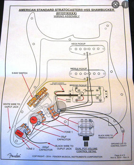 This is a diagram for a 2014 HSS "American Standard Shawbucker Strat". One pole of the regular 5-way deck of the switch controls the neck and middle pickups, while the 2 "Superswitch" poles controls the bridge HB and routes all 3 pickups to output. The switch options are just regular 5-way switching, the only real reason for the "discete switch" is to allow the use of a dual-gang volume pot to separate the V and T controls for the bridge HB. Not clear to me why they thought they needed this particular switch to do that . . . 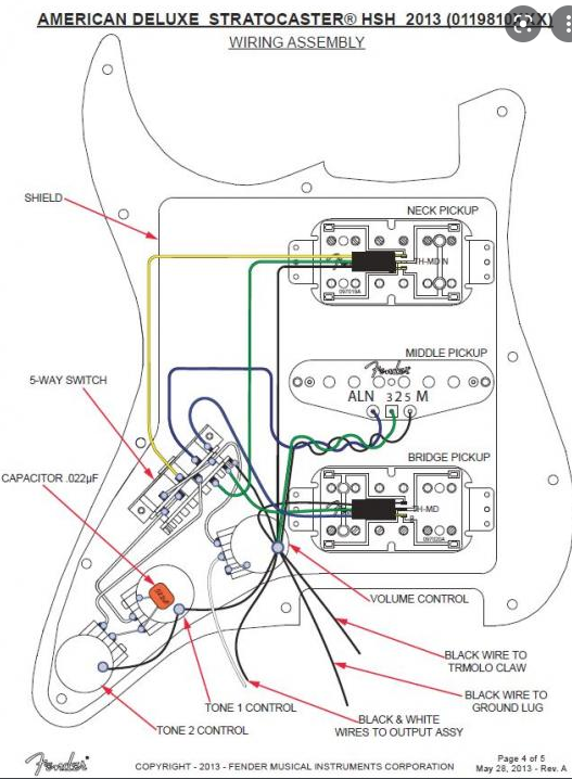 This is for a 2013 HSH American Deluxe Strat. Here the Half-Superswitch deck of the discrete switch is used to split the neck HB in position 4 and to split the bridge HB at position 2; the regular 5-way half of the switch is wired just like any Strat, so it gives the coil splits pluds the middle pickup at 2 and 4. They are only using one pole of the Superswitch half; again, seems the could have done this with a regular 5-way switch. |
|
|
|
Post by newey on Dec 26, 2021 18:05:05 GMT -5
So, like sumgai, I had never seen or heard of this switch before, and it does seem kind of silly. You wouldn't be able to do anything with it that couldn't be done with a regular Superswitch, but it is much more limited than the Superswitch, so unless there is a significant cost difference, I can't see much use for this.
Basically, what I would envision for this thing is that you would wire the one half of the switch that is a regular Strat 2P3T to give the standard Strat parallel combos. You would then need a second switch, a mini toggle or push/pull pot (could use an S-1 but would be overkill, you don't need the S-1's 4 poles), to switch from the regular 5-way side to the "half superswitch" side to give you other options. The second half is like a "half Superswitch", a 2P5T switch, so switching to that mode could allow for some series combinations, N + B, and so forth.
|
|
|
|
Post by newey on Dec 26, 2021 15:52:46 GMT -5
Ohhh, 😯 after rearranging things, my guitar has now been buzz free without even turning on that mxr smartgate. Earlier, I suggested a different circuit, room, etc. The lesson to be learned here is to isolate that it is, in fact, your guitar that is the source of the noise. Process of elimination, swap the cable first (a dodgy cable is always #1 on my hit parade when trying to track down noise), swap amps second, swap circuits third, start with a straight signal chain to the amp, no pedals, etc. If there is no change with any of these iterations, then, and only then, should we conclude that the guitar is the source. |
|
|
|
Post by newey on Dec 23, 2021 18:14:04 GMT -5
I'm onboard with the Yamaha guitars. I also have one of their dreadnaught acoustics.
Even in my 1998 cluelessness, I knew that fitment between the neck and body was important in bolt-on guitars. Having bought the body some time prior to the neck, and coming from different guitars although the same model, I was worried about fitment. But the neck fit perfectly, thanks to Yamaha's CNC machines.
I've never tried any of the Wilde pickups, but if I do so in the future, they'll be put into a different axe, with a better bridge, tuners, etc. You know, the old "lipstick on a sow" theory . . .
|
|
|
|
Post by newey on Dec 23, 2021 17:45:51 GMT -5
The air cleaner cover from just about any big American V-8, circa 1960-1980, could probably work as a resonator for a Dobro. But Ali Kat has beat you to this idea (as have numerous others, a quick google search will reveal) |
|
|
|
Post by newey on Dec 23, 2021 17:37:53 GMT -5
Many of us have, I am sure, scaled back our holiday plans this year. I choose to look on the bright side, I'm getting a small intimate family gathering rather than the hassle of a large party. Less stress, I'll be more relaxed, etc.
Merry Christmas to all of our members, and if you don't celebrate Christmas, then Happy Hanukkah, Kwanzaa, Saturnalia, Solstice or whatever you do celebrate.
|
|
|
|
Post by newey on Dec 23, 2021 17:28:57 GMT -5
ashcatlt- Your link to the NYT article just hits their paywall for nonsubscribers. cynical1 nails it. At the "time", audiences were scratching their collective heads at Miles Davis, Charlie Parker, Scott Joplin- the list could get pretty long. Years later, they're all "great". And Yoko was a performance artist before "performance art" was even a genre. In his autobiography, Stravinsky wrote: "At the beginning of my career as a composer I was a good deal spoiled by the public. Even such things as were at first received with hostility were soon afterwards acclaimed. But I have a very distinct feeling that in the course of the last fifteen years my written work has estranged me from the great mass of my listeners...They cannot and will not follow me in the progress of my musical thought. What moves and delights me leaves them indifferent, and what still continues to interest them holds no further attraction to me...I believe that there was seldom any real communion of spirit between us." Same thing we're talking about here.
|
|
|
|
Post by newey on Dec 23, 2021 6:04:26 GMT -5
Weren't the Rolling Stones singing "I can'T get NO satisfaction" btw Well, the double negative there may be appropriate. I suspect that back in 1966 Mick, Keith et. al. were getting all the satisfaction they could handle . . . |
|
|
|
Post by newey on Dec 22, 2021 22:19:14 GMT -5
I've posted this guitar before, many years ago, but I recently brought it back home from the cabin, where it's been pretty much a campfire strummer for the past eight years or so. It needed a restringing and general spitpolishing, which it has now had. But this is an opportunity for you all to mock me on how clueless I was when I built this. This was the first guitar I ever modified, back in about 1998 or so, but then I did the collage pickguard in 2010. It started life as a Yamaha EG-112, I got the body minus all the hardware off Ebay, and the neck off another EG-112 in a separate auction. The body was black poly-thick finish that took me a hootload of sandpaper to remove. It is far from perfect. And, I was too dumb to know that a regular Fender pickguard wouldn't just bolt on, you'll notice the butcher job I did cutting the new one in 2010 around the bridge area; the original black guard from 1998 was equally butchered. (I learned that it is hard to accurately cut a pickguard without proper tools- which I still don't have). And one of the pickguard screws hit nothing but air- and fell out years ago. My approach to the pickguard was "make it fit", and the pole piece alignment/spacing suffered as a result. I also didn't know that there were "white" pickup covers, knobs, etc., and also "cream" ones, the pictures on the web all looked alike. The redone pickguard was a clear one, and I glued the various ticket stubs to the underside with decoupage paste. That's the one thing that I thought came out pretty well. But it plays well and sounds decent, it has GFS pickups. IIRC, the body and neck cost me about $30, and I probably have about another $100 or so in import tuners and bridge,the pickups, and other hardware.   Here's the detail on the pickguard: 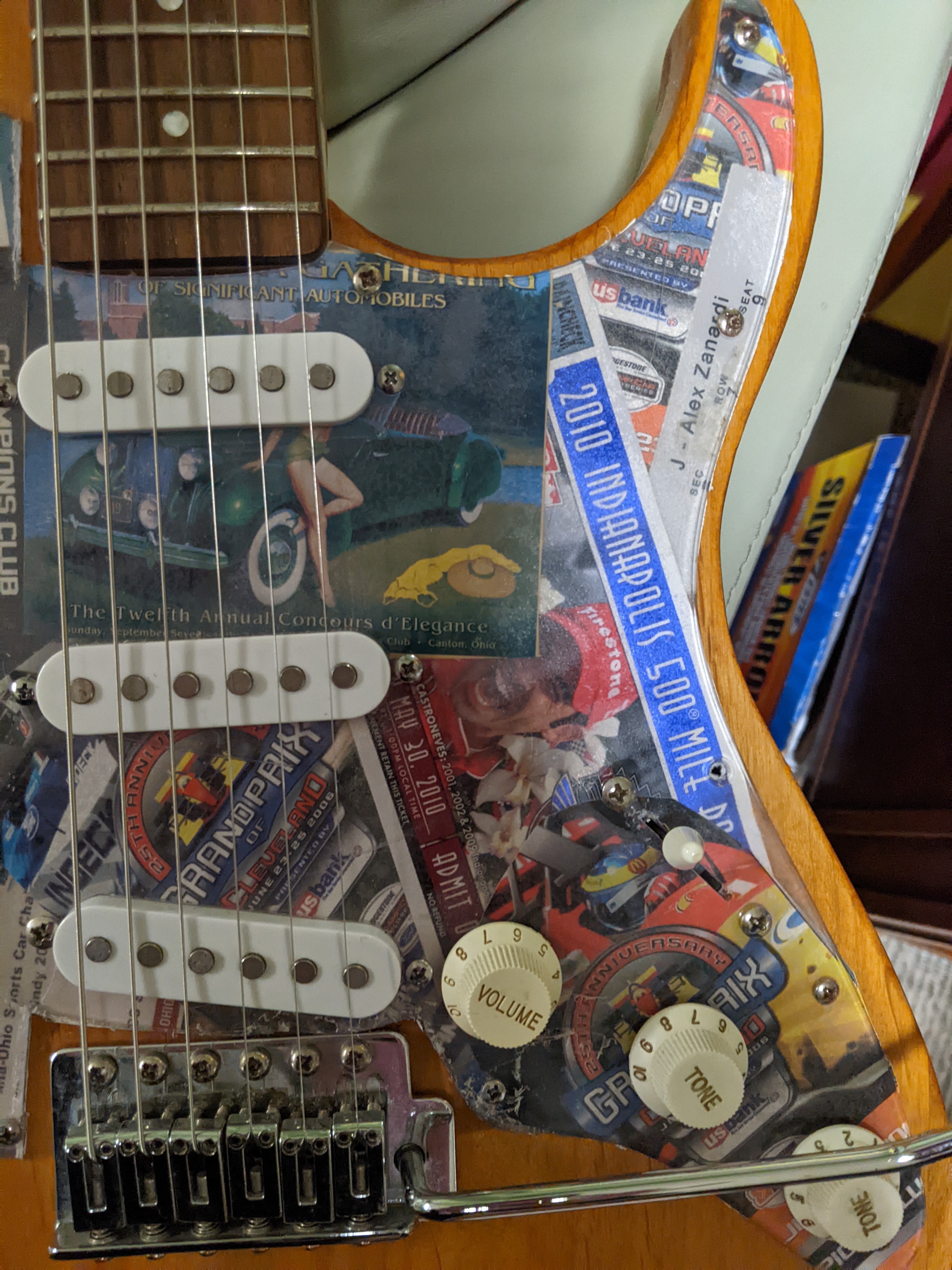 So, all y'all can all tee me up for random abuse over this one. The moral of the story is: "We all had to start somewhere".  . |
|
|
|
Post by newey on Dec 22, 2021 19:06:49 GMT -5
From your results, one might surmise that both wafers are facing in the same direction (say perhaps, track and wiper facing towards the switch). Can you verify this to be the case? I can't tell from an external view, with the 17mm footprint, the thing is mighty tiny. It is held together by fold-over steel tabs, so I suspect it could be fairly easily disassembled, but whether the element could be removed and fipped, I don't know, I'd have to (potentially)sacrifice one to look. I'm thinking it might not be do-able, given that the shaft has to hold the gangs while also moving up and down with the switch mechanism. |
|
|
|
Post by newey on Dec 22, 2021 8:52:19 GMT -5
I don't have an answer as to tapers or how useful the in-betweens may be. But I throw this out as I don't know if you saw this idea from ChrisK, using a 2-gang blend pot with a DPDT to select between series blending and parallel blending: guitarnuts2.proboards.com/thread/3863/series-parallel-blend-dpdt-switchThis could solve any issues with the blenders acting together. While shown as a blend of 2 pickups, it could just as easily blend one pickup plus the 3-way switch. The middle alone would be unavailable, though, without another switch or perhaps with using an On-On-On DPDT. Just a thought, anyway. |
|
|
|
Post by newey on Dec 21, 2021 21:52:48 GMT -5
frets: $5.53 USD at Mouser, plus tax. Measurement of the pots has been delayed by the need to acquire a new multimeter, the old one having exited the mortal meter coil . . . So, $37 later at Home depot, I got this one:  Commercial Electrics brand, which is (I believe) Home Depot's house brand. It is much more rugged than my prior meter, although bigger/heavier, but that's OK, I don't really carry it around much. It also has AAA batteries instead of the tiny button cells my old one used, a big plus when batteries need changing. And, although advertised as just an "auto-ranging multimeter", it also has a capacitance measurement function and a diode forward-bias voltage function. Anyway. here's the skinny: I first measured the total resistance across the outer lugs, top gang and bottom gang, to see if there was any significant variance. These are nominally 500KΩ, 20% tolerance. The top gang measures 460KΩ, the bottom gang is 464KΩ, so no significant difference and both within the mfr's tolerances. (P.S.- the switch works, too). At 50% rotation, on the top gang, between the CCW lug and the wiper, I get 24.96KΩ. Between the wiper and the CW lug, 432KΩ At 50% rotation, bottom gang, CCW to wiper is 23.97KΩ, from wiper to CW lug is 437KΩ These are the "dime-sized" 17 mm pots, and it's a bit difficult to be exact as to where 50% rotation is- I figured it as accurately as I could using the split in the shaft as a guide. Nonetheless, I was probably a mite off, looking at my measurements. But I trust that answers the question . . .
|
|
|
|
Post by newey on Dec 20, 2021 22:36:56 GMT -5
This started out as a thread about wiring this thing, but it's morphing into a build thread. Anyway, got the wiring to the half Superswitch done as far as I can go without working in the guitar. The big cap is C1= 0.015µf; C3 is 0.047µf; C4 is 0.0082µf. C4 was going to be .0015, but I had a bunch of the 0.0082s, so I went with that. 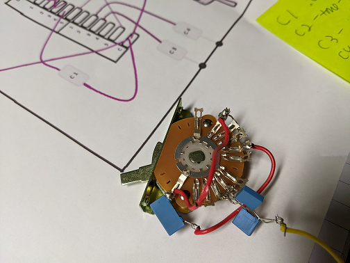 |
|
|
|
Post by newey on Dec 19, 2021 12:29:10 GMT -5
but you need to disconnect that connection to the volume pot and connect the LP switch to the toggle switch instead. Yes, I should have specified that. My diagram is just for the "middle pickup module" of this wiring,just showing how to incorporate it into the rest of the scheme. And, not knowing what pickups you had, I paid no attention to wire colors, I just made them different colors for sake of visibility. jhng's post above has the goods for you, easonsclassics. |
|


 )
)


 .
.