|
|
Post by ashcatlt on Mar 4, 2013 5:01:27 GMT -5
There's ratios all over the place! The ratio of one input to the other is 1:1 = 0db. I can call anything I want my 0db reference. It could be the voltage drop required to produce 1W through a 600Ω load. It could be 1V or 9V or 16V. But it's not. It's the Voltage of these identical inputs at this given frequency. As long as our circuits are linear the absolutes don't matter. Call it dbAsh.
Mixing the two inputs produces double the output. A 2:1 amplitude ratio is very close to 6db. It takes a small leap of faith to accept that -3 + (-3) = +3 unless you realize that you will be doubling whatever voltage -3db represents, so that the output has a 2:1 ratio to either of the inputs.
|
|
|
|
Post by ashcatlt on Mar 3, 2013 20:59:23 GMT -5
Let's say we have two identical signals. We assign a value to the energy in each at a given (low) frequency. Doesn't matter the actual V level, they're both the same, and this will act as our reference, so we'll call it 0db.
If we use an active mixing scheme to combine them without insertion loss, the output at that given (low) frequency will be +6db = double the V of either input. If we then apply a high pass filter (active again, because insertion losses will complicate the calculations) which is down -3db at that given frequency, the final output will be +3db at that frequency because +6 + (-3) = +3.
OTOH - If we apply the identical filters to each of the signals before the mixer stage, each signal will be at -3db. Mix them together and we get +3db again because -3db x 2 = -3db + 6db = +3db.
This implies that there will be no difference.
But it can't possibly be that simple. The interactions inside a passive guitar are pretty complex. Modeling (as JohnH suggested) will give more reliable answers.
|
|
|
|
Post by ashcatlt on Mar 2, 2013 22:27:25 GMT -5
You won't be able to check continuity through the caps because they block the DC voltage that your meter uses to test such things. If your meter does capacitance you could check that, else the best you can really hope for is to confirm that you haven't shorted anything you didn't mean to.
|
|
|
|
Post by ashcatlt on Feb 28, 2013 1:27:13 GMT -5
I guess I'm a bit confused there. I usually play the scale which fits the key. If we're in a major key, then I play the major pentatonic. Are we saying that country and southern rock are more likely than blues to be based on a major key? I guess that might be true in broad generality, but there are many exceptions on both sides. Robert Smith once told Guitar Player magazine that an important part of the Cure's sound comes from playing major scale melodies over minor keys, or vice versa, or something. He's kind of notorious for lying to and f  king with journalists, though... |
|
|
|
Post by ashcatlt on Feb 27, 2013 19:11:22 GMT -5
As long as all the "ground" wires meet it doesn't really matter where. You can do what you've described, or use a washer or big enough ring terminal around the shaft of one of your pots. Most blade switches (strat/tele style) have a case ground lug which can sometimes be convenient.
I (almost) never solder to the backs of the pots, but then most of my guitars don't have pots...
|
|
|
|
Post by ashcatlt on Feb 26, 2013 22:11:28 GMT -5
Now that is my kind of thing. I'm following you! You should check out [url=https://soundcloud.com/rob-fernquist/sets/shut-up-and-f k]some of my crap[/url] when you get a chance. |
|
|
|
Post by ashcatlt on Feb 23, 2013 23:56:08 GMT -5
Yes! An SPDT would do it. A center-off switch would also give you a No Load option!
|
|
|
|
Post by ashcatlt on Feb 23, 2013 14:32:23 GMT -5
Modern and 50's WiringThe sticky right above your post.  But the pictures don't seem to be coming up right now. JohnH, what's up wit dat?
|
|
|
|
Post by ashcatlt on Feb 8, 2013 23:15:25 GMT -5
Oh yeah! Sorry about that. Only three of the wires get to the guitar itself, so only one TRS jack there.
Seems it would be easy enough to put two TS or TRS jacks in the box for input, rather than looking for 4 contact alternatives.
Edit - You ninja'd me! The answer is no. There are several things not quite right, but ive kind of run out of time to go through it right now.
|
|
|
|
Post by ashcatlt on Feb 8, 2013 20:31:58 GMT -5
...unemployment line. Roughly translated, I believe that would be "Dole queue".  And I was just sure that cynical was going to chime in on the driving in snow thing seeing how he is a fellow rural Midwesterner. |
|
|
|
Post by ashcatlt on Feb 8, 2013 20:16:33 GMT -5
Wait! Back up a minute!
You (sort of) fixed the C3 thing, but that leaves C2 in the way.
That makes me look back at JohnH's diagram and his comments re: his original needing 3 wires and yours needing four.
THAT leads to the realization that the original doesn't have an INPUT jack!
Apparently the cable is meant to be permanently attached to the battery box, with the jack pictured acting as the OUTPUT.
You should have your INPUT RING connected in place of JohnH's OUTPUT TIP, but you still need a TRRS cable and matching jacks on both ends (one of which wants to also be N/O switched, for the battery thing) in order to get all four wires connected.
Are you up for a total of 3 jacks in the guitar? Since the 1/4" version of TRRS is elusive at best, I'm afraid that's where you're at. You could, I suppose, go with a 4-pin DIN cable, or those funky 4-pin XLR type things...
Or you could build the buffer into either the guitar or the box and use a simple TRS send/return deal...
|
|
|
|
Post by ashcatlt on Feb 8, 2013 16:30:18 GMT -5
Note that C3 needs to be parallel to the battery - between +9V and the input jack sleeve. As drawn the cap will block the DC voltage and leave the transistor unpowered.
Note also that JohnH's design uses the stereo input jack to disable the battery when the cable is unplugged. Since you're using the ring for other things, you've got it wired to be always on, so you'll either need a switch to turn the thing off (actually disconnect the battery, not just bypass) AND remember to use it, or a TRRS input jack. Never looked for a 1/4" TRRS jack. The 1/8" versions are out there (used in iphones and video cameras) but I just don't know about the bigger ones.
And speaking of switches you may think about a true-bypass stomp switch for the loop. While you're at it, why not stick a feedback knob in there too? I don't know what I ever did without my feedback knob! This might then lead to another switch for engaging the feedback. On mine, I just cut the track on the pot a la "no load", but find myself now sort of wishing I didn't have to bend over to go back and forth.
|
|
|
|
Post by ashcatlt on Feb 8, 2013 16:08:15 GMT -5
Now wait a minute here!
I took my driving test in a fricking blizzard. I've driven an 18 wheeler through Colorado in February, and through ice storms in Iowa. I've never been in an accident that caused real damage to people or property.
Not only do I know how to drive in the snow, I know when not to.
|
|
|
|
Post by ashcatlt on Feb 7, 2013 11:38:44 GMT -5
Hi AshCatlt, Q: I guess people always recommend putting the tamer cap between pickups as its easier to add it to the hot side of a pickup when you switch to a series configuration of pups? I guess I'm not aware of anybody "always" recommending anything re: a tamer cap. In fact, you're the only person I've ever seen use the term. A google search brings up 3 results, 2 of which are your posts on this forum. The order of passive components in series is arbitrary. All that really matters is the total impedance. If you start adding parallel components in between the series components, things get a bit more complicated, but for this thing with two pickups and a cap all in series, where you put what in the chain is a matter of convenience. Sure! Did I correct your question correctly? If so, then no...maybe...sort of...yes...  If the cap is connected to the same places that the T pot + cap are connected then it will act the same as if the T pot was at 0. But the V pot has two lugs which could be considered "hot", and it does make some difference which of these you use. (see 50s vs Modern wiring) Probably yes, for a number of reasons. First because the two pickups capture a different proportion of harmonics. Second because the two pickups will generally have different electronic characteristics, which will influence the response of the filter. Well, it was 03:30 my time when you posted. For me that's either "a little too late" or "way the f  k too early". |
|
|
|
Post by ashcatlt on Feb 6, 2013 23:33:05 GMT -5
I think the answer to all of those questions is yes. |
|
|
|
Post by ashcatlt on Feb 6, 2013 17:08:35 GMT -5
A high cut cap will be parallel to the pickup its meant to affect, and will be connected to both ends of the pickup.
A bass cut cap will be in series with the pickup. It will be connected to only one end of the pickup, and it doesn't really matter which end.
In your drawing any cap in circuit is in series with the pickup, and will act as bass cut. To get what you want I think you need to have the wire going from the left of the toggle to the rotary actually go from the right of the toggle (along with the wire that's already there, or just jumper from that rotary's left common to the right hand lug 3), ground the left hand toggle lug, and remove the jumpers on that left side of the rotary.
As JohnH said, though, the throws should be numbered the same for both poles. As you go around clockwise it will be either 5432154321 or 1234512345.
Most of the time rotary switches are limited to a total of 12 throws per deck. A single-decker can be 1P12T, 2P6T, 3P4T... But you aren't likely to find a 2P7T without adding a second deck, which will make it both deeper and wider.
|
|
|
|
Post by ashcatlt on Feb 3, 2013 15:07:22 GMT -5
My first "proof of concept" recording with the New Lorenzo's Tractor Live Rig in "one man band" mode was a late night, off the cuff cover of a Black Sabbath cover of an Aynsley Dunbar Retaliation song (Live at Five Miles from Nowhere on 12/9/12): One guitar and one voice. |
|
|
|
Post by ashcatlt on Jan 31, 2013 13:38:13 GMT -5
Well get on it there, mister! I was interested, but with only a minute of video it wasn't enough to really tell what it was all about.
Thanks for checking my stuff. "All Fall Down" is my departed brother's thing. There's more of that stuff - a lot of it much darker - but I haven't decide what to do with it yet.
|
|
|
|
Post by ashcatlt on Jan 30, 2013 18:42:50 GMT -5
...vibrato isn't tremolo... Tell that to Leo! |
|
|
|
Post by ashcatlt on Jan 28, 2013 18:32:37 GMT -5
That's pretty cool! Is there more?
I've watched your vid, now how bout you check out one of mine? Link's in my sig.
|
|
|
|
Post by ashcatlt on Jan 27, 2013 14:22:24 GMT -5
I've actually been holding out on this thread for a little while. Wanted to wait till I had really proven the concept and had everything together. Also wanted to have some pics to put up. I was going to just append another post to my other thread - the (current) Lorenzo's Tractor Live Rig. But then sg went and built a whole forum for it, so... Now, if you remember that thread, or if you click through enough links there, you'll find that we had been playing through this monstrosity:  I had, in fact, replaced the Dual MP with a Nady PRA 8: 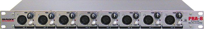 But the darn thing weighs as much as I do! I absolutely refuse to lift it. We talked about putting it on wheels, but that doesn't help getting it up the stairs and onto the stage. It also just makes it harder to fit it into anybody's vehicle on the way to/from gigs. On top of that, my signal sources (I tell them time and again that they are not "band members") are all caught up in married with children land and can't always get out to play whenever I find the opportunity. Now I can definitely find ways to make enough noise by myself to replace the rest of the band, but it does take a whole bunch of gear and only sort of does what I want sometimes. I've been playing around in the studio with guitar-to-MIDI stuff for the last year or so since I finally got a working hex pickup, and have gotten some pretty cool stuff using things like MIDI arpegiators and the like to generate "automatic" accompaniment from live guitar input. My studio machine is rack-mountable, and I've worked it out so that I can use VNC to control the thing from my Kindle Fire so that I don't have to carry a keyboard, mouse, or monitor with it. But it's still too big, and I just don't like the idea of dragging my main recording machine around to bars. So I went out and got an older Lenovo ThinkPad convertible laptop kinda like this:  and (thanks to jimmys69 at the homerecording.com forum) got the deal of a lifetime on a Tascam US1641 interface:  Stuck it, my Alesis D4, and my Roland GI10 into a 6 space Anvil case, and bought a standalone license for PodFarm2 and Reaper. Now I've got everything I had in the big rack and more! Lorenzo's Tractor is scalable from just me triggering drums, bass, and synth, like so: to the whole band, each with our own amp sim: As a full band the laptop does pretty much exactly what that whole rack of crap was doing. We still run all the pedals on the way in, except that the ring modulator has been replaced by a JS plugin that I coded my own self. The "Mr Rogers mic" function is also accomplished ITB, by sending the main mix through ReaTune, and having it generate MIDI notes. Right now I'm running the main guitar and bass inputs via DI into the mic pres, but I am not really happy about stepping down signals that are already not really hot enough, just to gain it back up at the pre or ITB. It's poor gain staging. But I just bought these DIs... Still a few things to sort out, but it quite definitely works as intended! I haven't taken any pics of the new setup. I can say that with the laptop in a bag jammed into the empty rack space, a rackmount power conditioner in the back, and the DI for the output, it's just about exactly as much as I'd want to carry at one time. And it slaps together in like three minutes and is mixed exactly the same as when we rehearsed last week. I tell the soundguy "Plug it in, turn it up, and blame me!" |
|
|
|
Post by ashcatlt on Jan 24, 2013 21:02:24 GMT -5
Apparently if you daisy chain the power off of a PSA adapter to both an ACA anda PSA pedal and also run your audio through both (doesn't matter which comes first), both will work just fine. This link talks about the difference and shows a way to mod your ACA pedal. I think just shorting the two wires together would have to be easier. |
|
|
|
Post by ashcatlt on Jan 21, 2013 1:16:51 GMT -5
Most of the active components - transistors, ICs, etc - can be considered purely resistive. Their reactive components are usually outside the scope of small signal, audio frequency circuitry.
A filter is a voltage divider. Consider the high-pass filter at the end of your circuit - C3 and R6. Picture C3 as though it were a variable resistor, only rather than turning it manually it automatically turns depending on the frequency it's fed. Higher frequencies turn the resistance way down. Lower frequencies turn it way up until you get to 0Hz - DC voltage - where it becomes an open circuit.
JohnH's suggestion that the out-Z is ~ 6.8K is only true for frequencies for which the cap is negligible. It's infinite at DC.
The connection between a source and a load (an output to an input) is also a voltage divider. Think of the out-Z as the "top" resistor, and the in-Z as the bottom and remember that both of these are "variable" by frequency.
Somebody on another forum once said "Everything useful is a voltage divider", and I'm still finding ways that this is true!
|
|
|
|
Post by ashcatlt on Jan 20, 2013 18:47:13 GMT -5
Impedance is frequency dependent resistance. Resistors and transistors have the same resistance no matter what frequency is going through. Capacitors have more resistance at lower frequencies (infinite at DC), and inductors have more at higher frequencies.
Bias usually is a voltage that we add to the signal in order to get it to swing in a range we can use in our circuit. Coming into the circuit usually the guitar signal swings around 0V. Given a single-sided supply (like a battery, or DC wallwart), the active portion of the circuit can not supply anything less than 0V, so the "bottom half" of the signal must be cut off. We add a DC voltage to make the guitar signal wiggle around the middle of the power supply so we can amplify the whole thing. It is sometimes also called a "reference voltage" (Vref), "virtual ground", or even "audio ground".
|
|
|
|
Zoom R8
Jan 17, 2013 8:23:16 GMT -5
Post by ashcatlt on Jan 17, 2013 8:23:16 GMT -5
I have no experience with the Zoom box, but I do have a PodStudio UX1. I won't take it off the desk in the studio. The R8 looks a lot more flexible. The faders alone have me thinking... Need to sell some crap before I can make that upgrade! Anyway,  |
|
|
|
Post by ashcatlt on Jan 10, 2013 23:28:05 GMT -5
Looks cool and glad its working out for you.
The noise comes from having the "hot" wire of the cable connected to the amp input and open at the other end. It acts exactly like an antenna injecting all the EM noise flying around the room directly into your amp. It would be much better to short the unused output hot to ground. The way you're switching the grounds doesn't really allow this without another pole on the amp select switch, and you'd need an on-on-on to short both in the middle position.
You don't actually have to switch the grounds, but the way you've got it now in a non-conductive box manages to avoid the whole ground loop issue.
|
|
|
|
Post by ashcatlt on Jan 6, 2013 19:31:04 GMT -5
I'm kinda tempted to invite myself to this party in Chicago. Come on down! This would be incredible. Anything I can do to raise that temptation, besides the obvious gas money? Oh if only... We're a little too late for me to get a three month LOA and still have a job to come back to. Then, I'd have to replace that income. You'd probably be surprised at how little that would take, but then I've got these short people who depend on me. It would be a great experience for them, but that's a whole different trip... Definitely keep me in the loop, though. Chicago is a little more than a "day trip", but I should be able to swing it given a little notice. |
|
|
|
Post by ashcatlt on Jan 6, 2013 2:43:29 GMT -5
I'm kinda tempted to invite myself to this party in Chicago.
I have an erratic schedule, but it's set 6 weeks out and I refuse to give those bastards any more of my time than absolutely necessary, which right now means I usually have four day weekends.
And yes, my email address has been the same since 1998. I've had several others on domains which no longer exist, but microsoft's free version which was the first I could check from anywhere in the world without proprietary software is the one I use.
Heck I'm half tempted to meet you in DC and escort you across this fine land of theirs! I am a professional driver...
|
|
|
|
Post by ashcatlt on Jan 3, 2013 21:52:02 GMT -5
I'm pretty sure Boss did this specifically so that they could sell proprietary power supplies.
There is no other good reason.
It goes along with that "polarity protection" diode reverse biased across the rails. If you connect the wrong polarity, the circuit is protected for a bit while the power supply and the diode battle to the death. If the diode loses (it always does!) then everything else in the pedal which is polarity sensitive starts popping.
When you send it back for warranty service they can say "You didn't use an approved Boss brand power supply, and we have the exploded diode to prove it."
|
|
|
|
Post by ashcatlt on Jan 3, 2013 19:39:33 GMT -5
Pretty much anybody who uses that kind of connector on a pedal for DC power uses the "Boss standard". If you had connected the wrong polarity wallwart you would have had nothing at all - no LED, no sound - until either the pedal or the wallwart let out their magic smoke.
You could open up the pedal, connect the wallwart, and measure DC voltage on the inside of the jack.
My completely way out guess is that for one reason or another your supply is coming in very low. This could cause distortion in the compression circuit, and dim LED, and (here's where I go out on a bit of a limb) possibly not allow the transistors which control the bypass scheme to completely open or close or whatever so that they are just halfway open and you're getting a mix of the clean bypass signal with the distorted comp signal. Maybe?
Corrosion on the power jack could cause this. It should be sort of self cleaning. Take that daisy chain thing (not connected to the wallwart, we want no power for this) and jack it in and out a few times. Maybe very gently push at an angle to force a bit more contact pressure. Don't break it loose from the PCB! You could help this along by first spraying a little electronic contact cleaner, some denatured alcohol, or even isopropyl (rubbing) alcohol.
HTH
|
|


