|
|
Post by ms on Nov 2, 2020 11:47:21 GMT -5
I would divide the inductor into two that sum to the original and put a capacitor across the break. I was thinking about this model, what should the value of a "break" cap value be, approximately? Depends on where the break is and how the pickup is wound. I think that is why the effect is not observed consistently. |
|
|
|
Post by ms on Nov 2, 2020 11:45:19 GMT -5
I have a 250K with a 47 capacitor, it sounds nice but is pretty bright and shrill when out of phase, maybe going to a 22 capacitor with 250k will work since the trisonics have a lower inductance. 250K 22 cap 250k 47 cap 500k 22 cap 500k 47cap(way to bright) So many options lol To make it less bright, you need to decrease the value of resistance across the pickup. You could use a smaller value tone or volume pot, or add some fixed resistance in parallel with the pickup. |
|
|
|
Post by ms on Nov 2, 2020 11:30:35 GMT -5
You might have some capacitive coupling across the break. This would work better at high frequencies. I see. Can you show me an equivalent pickup circuit when this happens? I want to understand it better. Thank you! I would divide the inductor into two that sum to the original and put a capacitor across the break. |
|
|
|
Post by ms on Nov 2, 2020 11:25:44 GMT -5
I have a 250K with a 47 capacitor, it sounds nice but is pretty bright and shrill when out of phase, maybe going to a 22 capacitor with 250k will work since the trisonics have a lower inductance. 250K 22 cap 250k 47 cap 500k 22 cap 500k 47cap(way to bright) So many options lol Someone said it before, and I will say it again: the capacitor only matters only when the tone pot is turned down, usually well below 10. In any case, a smaller value of capacitance would be expected to not cut so much high frequencies. |
|
|
|
Post by ms on Oct 30, 2020 19:04:26 GMT -5
You might have some capacitive coupling across the break. This would work better at high frequencies.
|
|
|
|
Post by ms on Oct 8, 2020 10:33:56 GMT -5
Sensible switching for a 3 pickup Les Paul is not so easy. You have two volume and tone controls. Maybe use one pair on the bridge pickup and switch the other pair between the other two pickups. The problem is to find a lever switch that will do this. A four pole rotary, sure, but you need a small one with a long thread. But it will only feel like an original LP if it has a lever switch BR-Mid-NK. The way it is now it is just an LP with a different kind of sound in the switch position that is normally for the neck pickup, which might be the best you can easily do, although some people might prefer to connect up the middle and bridge pickups instead. You can always use push-pull switches on the pots to do almost whatever you want, but that always seems messy, non-intuitive, and complicated to me. But it would be tempting to use such a switch to go between the neck and middle with the lever switch in the "neck" or "both" positions. I've been thinking about this ever since I received the guitar. I'm thinking about having the middle and neck pickups have on/off push pulls, with the neck pickup "on" by default, and the middle pickup "off" by default, so that that it behaves like a stock Les Paul with no middle pickup, but by way of the push pulls, any parallel pickup combination can be had. I was hoping to do an "all pickups in series" option, because I think that might represent the maximum output that could be achieve by any conventional electric guitar, but it would probably sound terrible. So if you are in the normal LP mode on the bridge pickup, to switch to the middle alone, you have to move the lever switch and both push/pulls. Depending on the order of the switching, you might have all pickups off during part of the switching. All three in series might work with huge gain and distortion. After the recently deceased guitar hero, you could call it "Van Halen". |
|
|
|
Post by ms on Oct 8, 2020 7:30:22 GMT -5
Sensible switching for a 3 pickup Les Paul is not so easy. You have two volume and tone controls. Maybe use one pair on the bridge pickup and switch the other pair between the other two pickups. The problem is to find a lever switch that will do this. A four pole rotary, sure, but you need a small one with a long thread. But it will only feel like an original LP if it has a lever switch BR-Mid-NK. The way it is now it is just an LP with a different kind of sound in the switch position that is normally for the neck pickup, which might be the best you can easily do, although some people might prefer to connect up the middle and bridge pickups instead.
You can always use push-pull switches on the pots to do almost whatever you want, but that always seems messy, non-intuitive, and complicated to me. But it would be tempting to use such a switch to go between the neck and middle with the lever switch in the "neck" or "both" positions.
|
|
|
|
Post by ms on Sept 21, 2020 7:00:15 GMT -5
The plated steel pole pieces on most humbuckers and cheaper strat pickups with bar magnets below the coil seem to be a major cause of loss of Q. There is a grade of stainless steel, 430FR that is magnetic and is used for solenoid cores. It has a resistivity about 4.6 times higher than mild steel and quite high permeability. It might allow a strat pickup with adjustable poles and high Q to be made.
The magnetic and electrical properties look great. I looked around a bit for screws made from it and did not find anything. It is machinable, and so maybe you could cut a thread on a rod for adjustability. But maybe chemical and/or heat treatment is necessary afterwards. That might be a problem. |
|
|
|
Post by ms on Sept 16, 2020 17:20:34 GMT -5
What a great resource1 And I see that individual parts can be directly downloaded from that page too. I find it remarkable how the Germans seem to have embraced the technical side of guitar physics more than any other race. There are a few cases where the testing results are not completely available in the free downloads. (At least this was so a few months ago when I last looked in detail.) You had to order printed versions. I would be willing to purchase, but I would prefer electronic format; for me, a good quality computer screen is easier on the eyes than the printed page. |
|
|
|
Post by ms on Sept 8, 2020 6:50:19 GMT -5
I actually had one of the long magnet copies and built it into an archtop, but this was long before I got involved in pickup measurements. What I remember most about it was the excessively loud B string, even with the notched pole, and the extraordinary susceptibility to magnetic hum.
I would guess that the long magnets might have a marginal effect on the linearity by reducing the rate of variation of the magnetic field with distance from the active pole but they were made that size because it was the only way of maintaining a decently strong field above the pole with the available magnets while leaving the space above the strings clear. Earlier designs had partially closed the magnetic circuit above the strings. I think it was originally intended for steel guitars and the industry abandoned it as soon as better magnets became available.
It was, however, the pickup on Charlie Christian's guitar so it still has an emotional pull for many jazz guitarists who think that it has a magical sound. As ms says, appearance is probably a major part of its appeal.
It would seem that the permeability of the cobalt steel magnets is very high, although I am not sure I have found info for the right material. If so then you have the double whammy of a material with both a very weak permanent magnetic field and a very high sensitivity to stray magnetic fields. The very large pieces attached to the steel core of the winding are a very efficient hum detector. It probably was not as much of a problem when it was first used as today. There was no switching equipment at the time, such as light dimmers and switching supplies, and so you just had 60 (50) Hz and low number harmonics. The speakers then probably had not much bass, but I bet it still required careful placement of the amp to minimize the effects of its power transformer. |
|
|
|
Post by ms on Sept 7, 2020 6:39:15 GMT -5
This is a copy of a CC pickup: www.ccpickups.co.uk/about.html. If you want to put one on a Tele, you would have to do a lot of work: route a huge hole and put on a spruce top. I doubt that the huge cobalt steel magnets as opposed to normal sized AlNiCo bar magnets do much to the sound, but if you pride yourself on making faithful copies, how can you call it a CC pickup copy if it does not have the correct magnets? If you can figure out what the frequency response of the original CC pickup is, then I think you can duplicate that in a single coil pickup without either making it a non standard size or making it have the appearance of a CC. But I think the appearance is 95% of what people want, which I think agrees with Antigua's opinion.. |
|
|
|
Post by ms on Aug 11, 2020 9:49:59 GMT -5
Yeah that's something I hadn't considered. We might expect people to say "it just sounds louder", but instead we say "it sounds better". And this is yet another example of how identical pickups can result in non identical listening experiences. I think that this listening test is telling us that there are enough variables in the process that controls how an electric guitar sounds so that really small differences in the pickups are swamped by other factors. This is pointing in this direction: you can make measurements that are more sensitive to pickup differences than matter in practice. I am not saying not to measure, but rather saying that in the design process, proceed with measurements for the best way to establish differences, and then see what really matters using good listening tests. |
|
|
|
Post by ms on Aug 8, 2020 5:54:57 GMT -5
When there were "stereo stores" where you could listen to different systems and pick out the best you could afford, a smart salesman knew that you played the one you wanted the customer to buy just a little bit louder while pretending to adjust the volumes the same.
And that is so simple compared to to a situation where distortion is intentional, and a player is adjusting to a given set of conditions.
|
|
|
|
Post by ms on Jul 22, 2020 6:18:37 GMT -5
This post and others you've written are dense with technical terms and I would guess some formal education is physics, so I tend to get lost. By "decreasing B" field, does this mean you're essentially measuring the effects of magnetic string pull? When I've tested string pull and harmonics, I found that where the pickup was located along the strings had a big influence on the how the higher harmonics were affected. Increased string pull was sort of like a soft pinch harmonic, it would weight harmonic amplitudes similar to if you were to perform a pinch harmonic at that location, but to a much lesser degree, since the magnetic pull is orders less disruptive than a finger touching the string. I am sorry about the confusion. I did not connect this up with previous discussions. It has been longer than I thought since they took place, and it has taken a long time to find the time to write up these measurements made a while ago. The magnetic field decrease here is the decrease of its strength with distance from the pole piece as the string vibrates in the direction towards and away from it. Using an actual pickup output, what you would measure given the effect of some assumed nonlinearity is predicted by computer program. |
|
|
|
Post by ms on Jul 20, 2020 12:40:54 GMT -5
|
|
|
|
Post by ms on Jul 20, 2020 12:35:58 GMT -5
Summary of the process: Sample and store the signal from a picked string. Integrate the signal to get the displacement. Input the signal to a non-linear function and get a modified displacement. Differentiate the result to get a modified velocity. Compare the spectra of the velocity signals (before and after the non-linear function is applied). First consider the non-linear function. In order to simulate the effect of a B field that changes with distance from the pole piece it needs to have a “gain” that falls off with positive string displacement. This could be characterized by a graph of displacement out versus displacement in. I prefer to use the slope of that curve, kind of a gain. The function used is the square root, after adding a constant to the input, and using scale factors before and after as necessary. The first plot shows this function; the gain varies by about a factor of 2.5. This corresponds to variation in B of 2.5 as the string moves from the most negative position (closest to the pole) to the farthest position during vibration. The displacement values are arbitrary, and a constant is added before the square root operation in order to get this curve.  The orange curve on the next plot shows the pickup output early in the excitation just after the pick releases the string. (The pickup output should already have some non-linear effect, but this does not mean we cannot add more.) This is a single coil type bridge pickup, E6 string, picked just on the neck side of the pickup. The pickup has a resonant peak and so its output differs from the velocity at the higher frequencies. (The blue curve is after the distortion is introduced, to be discussed below.) The next plot shows the same curves after about four seconds when the signal has decayed considerably. The orange and blue are almost identical, meaning that there is essentially no distortion (and that the gain in the software has been carefully adjusted).  It is necessary to integrate the measured velocity (pickup output) in order to get the displacement. This integration greatly increases the low frequencies in the beginning of the signal as a result of the string motion induced by the picking. Most of this can be eliminated by starting the analysis when the string is released. However, there still is still the matter of the constant of integration. This does not seem to be a problem because a constant is added to the signal as part of the input to the non-linear function generator. However, my sampling device is not dc coupled, and so the level introduced at the start of the string vibration becomes a decaying exponential as the coupling capacitor charges/discharges. I have subtracted out this exponential after finding its parameters using trial by error and visual inspection. It did not seem necessary to write a fitting program. The result of integration of the sampled pickup output (velocity) is the orange line in the next plot. (The blue is result of applying the non-linear function to the data shown in the orange curve.) The first msec or so is the result of the combination of the picked wave passing over the pickup and its reflection off the bridge, which is not far away. At about 12 msec we see the combination of that reflected wave and the original wave heading towards the nut after it reflects from the nut and passes over the pickup. And so on.  The distorted displacement is stretched in the negative direction significantly, but there is not so much difference otherwise. The distorted velocity shows that the large peaks have increased in size. The final plot shows the spectrum. (It is in the next post) Power in the lower harmonics relative to the fundamental has increased. Surprisingly, power in some of the higher harmonics has decreased. I would judge that the nonlinearity has a significant audible effect, but it is not an essential part of the electric guitar sound. |
|
|
|
Post by ms on Jun 8, 2020 13:19:00 GMT -5
I can see that I made an error in the Spice schematic for simulating the effect of the string magnetisation. Instead of treating the magnetisation as a multiplier of the differentiated sine output it should have been multiplied by the sine before differentiating. This steepens the slope but leaves the general character the same. With regard to the Hammerstein formula from the paper. The non linear part maps volt seconds to displacement from an origin at 5mm. Volt seconds is, of course, magnetic flux which when differentiated gives the pickup output in volts. The non linear formula, then, seems to be mapping how the flux in the coil varies with displacement of the string from the reference position. There will also be an added fixed amount of flux which is not included since its effect would disappear in the subsequent differentiation.
What I find curious is that the gradient of the curve increases at the extremes for both positive and negative excursions. I can't work out what causes that in such an obviously asymmetrical device as a strat pickup.
Arthur That does seem strange; surely the sensitivity must decrease with greater distance from the pickup, leading to asymmetrical distortion. |
|
|
|
Post by ms on Jun 6, 2020 14:24:51 GMT -5
Now consider holding the string in a half sinusoidal shape rather than a triangle and releasing it. This excites fundamental only. Then distort it and take the derivative. The result:  This is very different. I think we need to use a realistic waveform (that is, a realistic level of harmonics) and distort it in order to get a better idea of how the distortions appears. |
|
|
|
Post by ms on Jun 6, 2020 13:46:09 GMT -5
I thought it might be worth trying another more intuitive approach. Drive with a displacement wave, differentiate it and then multiply the output by the non linear displacement characteristic. Easily done in Spice. I chose the 1/(1+k*displacement) response from Zollner's article, which by the way is also a good fit for the total flux intercepted by the string. I was curious to know if this would give the same sort of pulse response. The drive is a simple triangular wave which differentiates to a square wave. The result should be obvious, on reflection.
Arthur
Yes, it is as simple this: if you reduce the sensitivity as the string goes away from the pickup, you get it back as the string returns towards it. |
|
|
|
Post by ms on Jun 6, 2020 5:58:16 GMT -5
Wikipedia: The Hammerstein model consists of a static single valued nonlinear element followed by a linear dynamic element.
That is, the first block is a function that gives an output for each input, but the plot of output vs input does not have to be a straight line. It is up to you to specify what it is. (I suspect that a specific parametrized non-linear static model contained a theMatlab Simulink package is sometimes associated with the term "Hammerstien".)
The following linear block does contain time, and in our case it is a differentiator, converting displacement to velocity.
|
|
|
|
Post by ms on Jun 5, 2020 11:36:25 GMT -5
Actually, the non-linearity is so large that it can be observed directly in the pluck response of the pickup and it explains a phenomenon that I found couldn't be modelled by any kind of pluck excitation of my delay line model. Note how, in the following waveform, the top and bottom of the square pulses both slope downward. I could find no pluck waveform that could reproduce that behaviour. This is the initial response of a strat fingerboard pickup.
.
Does this feature (both downward sloping pulses) decrease in relative importance when you reduce the intensity of the picking? |
|
|
|
Post by ms on Jun 5, 2020 11:05:27 GMT -5
As I understood their statement, the authors noted that there was an initial transient from the stimulus (like a guitar pick creates) and after that had decayed then they observed that the remaining generated pickup signal waveform, now with fewer transients and easier to observe, differed from the measured string movement as a result of non-linearities in the pickup response. The following are my thoughts, and not explicitly stated in the paper nor defendable with any measurements I have made: Assuming that the observed non-linearities are a property of the pickup response that is also present (but harder to observe visually) during the attack transient created by plucking the string, then it seems to me a reasonable inference that this generates harmonics (as any non-linearity would) during the transient, too. This would, to me, account for some of the tone of the pickup and could well be different between pickup designs and magnet materials used. OK, I can see you might want to avoid the initial transient. But it seems that they should compare the pickup output with an independent measure of string velocity (a linear measurement) in order to see the excess harmonics generated by the non-linearity. They mention a vibrometer (not sure what that is), and it seems to measure displacement. So in order to make a comparison, they have to differentiate the vibrometer output or integrate the pickup output. I wonder if this can be done accurately enough to get a good measurement of the harmonics due to the non-linearity. |
|
|
|
Post by ms on Jun 5, 2020 7:06:28 GMT -5
"As
expected, the string displacement is distorted just after the excitation.
It becomes less and less distorted as the harmonics of higher
orders fade with time. The output signal of the pickup exhibits the
same kind of behavior with time. One can notice that the output
voltage is more distorted due to pickup non-linearities...."
Can anyone explain to me how these non-linearities are observed? Higher harmonics decay naturally with time. I think it would be difficult to determine the level of harmonics due to non-linearity in a background of decaying string harmonics.
|
|
|
|
Post by ms on Jun 5, 2020 6:40:57 GMT -5
You have not shown that the non-linearity has any significant effect on the sound. Seems premature to suppose that there might be differences between pickups. The point is that harmonics are much smaller in amplitude than the fundamental (this is something I *have* seen myself) and that is where the difference between a guitar and, say, a trumpet exist if playing the same note. If that were true, then an electric guitar should would sound like a sine wave with a bit of distortion. The relative level of the fundamental varies with conditions and can sometimes be quite small on E6 open since the amp-driver-cabinet can attenuate bass a lot. |
|
|
|
Post by ms on Jun 4, 2020 19:23:47 GMT -5
it is quite reasonable to expect different pickup designs to introduce harmonics in slightly different ways and therefore to sound different. I am prepared to accept the possibility that these differences are subtle. You have not shown that the non-linearity has any significant effect on the sound. Seems premature to suppose that there might be differences between pickups. |
|
|
|
Post by ms on Jun 4, 2020 17:32:12 GMT -5
I could not tell the difference between a celtic harp compared to a guitar if I were to look only at waveforms and spectral measurements. The altering of the relative strengths of harmonics caused by sampling the string at one or a few narrow regions with one or two coils or multiple pickups has a definite audible effect and can also be observed in a spectral measurement. This differentiates an electric guitar from an acoustic stringed instrument. I agree wood makes a difference. The vibration of a string, what the pickup senses, is affected by its environment, and also there are various ways to enhance this effect. There is modeling that shows that non-linear effects can modify the ratios of harmonics. That must change the sound some, but is it really enough to matter when there are other ways that make larger changes? Also pickups with strong eddy current effects have an additional degree of freedom in the frequency response compared to those with small or no eddy current effects. With eddy currents, the damping is a function of something like the square root of frequency, and so the shape of the broad resonant peak is affected. I do not know if this makes a practical difference. |
|
|
|
Post by ms on May 31, 2020 6:08:48 GMT -5
The integral is a result of a calculation from the known velocity? Is the reason why the high E and the low E have a similar output/loudness because both strings displace at a similar velocity? Yes, the displacement is calculated from the measured velocity. Point zero in the displacement is point one of the velocity minus point zero of the velocity. (Should multiply by the time increment between samples, but that is just assumed to be one since we scale this to fit on the plot anyway. This simple process also does not properly center the results, but the sampling rate is high enough so that this is not too important.) Point one of the displacement is point zero of the displacement plus the difference between point 2 and point 1 of the velocity, and to get the next value of displacement we add to the current value the next velocity difference times the time increment. This is an approximate numerical integration. If we had the displacement, we would estimate the velocity by subtracting neighboring values and dividing by the time increment. (Or we could use a more complicated process using more than two values of displacement to get a properly centered velocity.) Integration just goes the other way to get displacement from velocity. The integration starts at some particular time, and we should use the value of the displacement in the calculation of the zeroth point. We do not know this, but assume it is zero. This is the reason for picking towards the nut end of the string so that the initial displacement over the pickup is not very large. This seems to work out: when the displacement is at an extreme (positive or negative), the velocity is zero. I think the high E and low E are very different. With the high E only a quarter as many harmonics fit into the bandwidth of the system, and the string is plain rather than wrapped. I used the low E (6) because the velocity has so much detail because of this. |
|
|
|
Post by ms on May 30, 2020 14:26:35 GMT -5
Actually, thinking a bit deeper about the Spice model, it models the transient behaviour OK and reproduces the sound of the string, but it doesn't consider the displacement of the string before the pluck release. This would have to be modelled as a charge distribution on the delay lines but there is no mechanism within Spice for doing that with the lossless delay lines.
There will obviously be distortion produced by the pickup non-linearity. Even the simple fundamental will be multiplied by a non-linear version of itself phase shifted by 90 degrees but this seems only to alter the shape from about half way up the sloping edges without compressing or expanding the peak.
Arthur
Just for fun, a measurement. The setup uses a short cable to the scope; the neck pickup of the guitar is heavily loaded to give response nearly flat passed 10 KHz. The E6 string is picked at the fifth fret, making the initial displacement over the pickup small. The blue line shows pickup output (velocity). The other is its "integral", the displacement, assuming zero initial displacement. Horizontal scale is time in seconds; vertical scale is arbitrary units, with data scaled so that both lines fit on the same arbitrary scale. 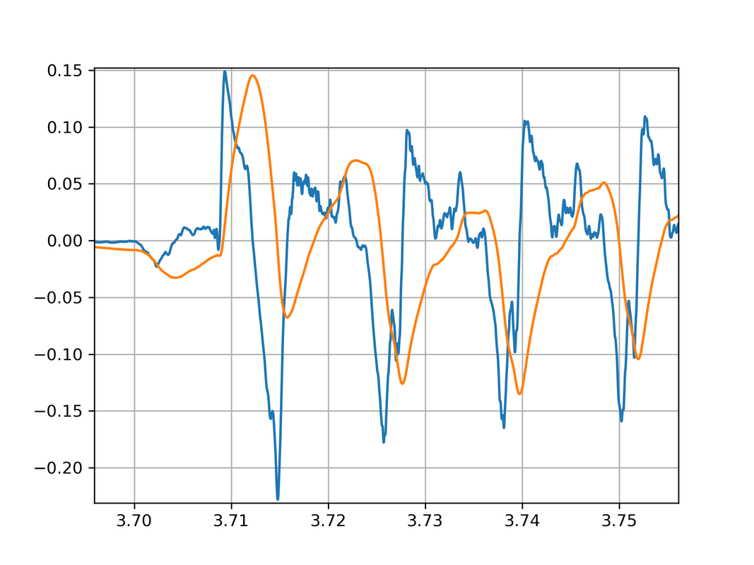 |
|
|
|
Post by ms on May 29, 2020 14:40:19 GMT -5
My understanding is this: The pick draws the string away from equilibrium. Assume the pick is at the middle of the string. Just before the pick releases the string, the displacement is maximum and the velocity is zero. The pick releases the string and the restoring force increases the velocity from zero in the direction of equilibrium. As the displacement passes through zero, the restoring forces also passes through zero and increases in the opposite direction. The string decelerates and the velocity goes to zero when the displacement is maximum in the opposite direction from the start. This is more complicated if you pick toward one end, but I think maximum displacement with zero velocity is an inevitable boundary condition. This is all happening on a transmission line. When the pick releases the string the restoring force due to the tension in the displaced string is no longer balanced by the pick force so there is an impulse of force at the pick position. The string impedance is essentially resistive so there is an immediate pair of acceleration spikes that travel down the string in both directions. These spikes reflect inverted from the bridge and nut because the impedance at those boundaries is much higher than the string impedance. This pattern of impulses travels up and down the string, diminishing and rounding off slowly as time passes because of slight imperfections in the reflections and frictional losses with the air and inside the string. The wave velocity on the string is also slightly dispersive, so the impulses tend to spread with time.
There is no way that the string can immediately respond as a whole to the pluck. There is a wave velocity sqrt(T/m), where T is tension and m the mass per unit length. This is equal to 2 * L * f0 (L = string length, f0 = frequency). No disturbance can travel down the string faster than that.
The Spice model reproduces much of this tolerably well and adding the extra integration step reveals how the displacement over the pickup changes during the velocity spike.
Arthur
Yes, I think looking at the problem as a transmission line is a great way to do it. But looking at the standing wave solutions should work as well. I considered only the fundamental in my previous post. Really you should represent the shape of the string stretched by the pick just before release as a Fourier series of fundamental and overtones and then run the solution forward from there. But either way, the relationship between an extreme of displacement and the velocity is the same: it is where the string stops and then starts moving in the other direction. And so this is where the pickup, sensitive to the velocity, has zero output. |
|
|
|
Post by ms on May 29, 2020 11:48:24 GMT -5
I have been looking at the delay line Spice model of the string, where the pluck is a burst of acceleration and we integrate to get the velocity for the pickup output. Adding a further stage of integration gives the displacement. In the early part of the waveform, the acceleration consists of pairs of spikes which, on integration give an alternating series of wider single spikes. Integrating these gives a series of double ramps. The sloping portions of the these double ramps coincide with the velocity spikes. In other words, the string displacement takes place during the velocity spikes and any variation in the pickup gain due to the displacement will modulate the shape of the spikes. This means that the pickup non-linearity will be manifest during the early few tenths of a second of the note, i.e. during the period that most defines its character.
Arthur My understanding is this: The pick draws the string away from equilibrium. Assume the pick is at the middle of the string. Just before the pick releases the string, the displacement is maximum and the velocity is zero. The pick releases the string and the restoring force increases the velocity from zero in the direction of equilibrium. As the displacement passes through zero, the restoring forces also passes through zero and increases in the opposite direction. The string decelerates and the velocity goes to zero when the displacement is maximum in the opposite direction from the start. This is more complicated if you pick toward one end, but I think maximum displacement with zero velocity is an inevitable boundary condition. |
|


