|
|
Post by ms on Apr 29, 2021 14:53:36 GMT -5
Thanks, That does clear it up quite a bit. So apparently the source of my confusion was that I ignored the pole pieces, and it's the pole pieces that are in an external magnetic field of the pickup magnet. It's been more than a decade since I studied this stuff at uni, and of course we didn't specifically look at guitar pickups. So I was thinking more about the more usual case of current in the coil inducing the magnetic field and how materials around the coil respond to it, obviously the field of the pickup magnet is much stronger. But am I right in thinking that it's the currents induced in the non-magnetized steel ruler which increase the inductance in that case? Also, if you or anyone else can provide more insight as to the results in the video, I'd be interested to learn more. Eddy currents reduce the inductance, not increase it. But if you make the measurement at 120 Hz, the frequency is too low for there to be significant eddy current effects in a pickup. The ruler just adds more steel to the system; exactly how this increases the inductance is a complicated question. I would model a 2D approximation in FEMM to find out. Maybe that guy really does believe what he is saying, but notice that when he told you that the strength of a magnet does not influence the inductance, and to prove that you demagnetize a magnet and then put it back in the pickup, he did not actually do that test. For example, a very strong magnet saturates the cores, or at least gets to a flatter part of the curve, reducing their permeability maybe to just about one, and thus decreases the inductance relative to a weaker magnet. It is all in the set of hysteresis curves. Certainly the strength of the field does influence the inductance, and by not understanding what he is doing and selecting results carefully, he can get results that reinforce his lack of understanding. This is, after all, a complicated subject. |
|
|
|
Post by ms on Apr 29, 2021 13:29:57 GMT -5
I am not sure how deeply you want to go into this, so I will give a short, general answer. The magnet does not alter the inductance because of its permeability. The permeabilities of the magnets are low compared to that of the steel in the cores; how could they have any such direct effect? Instead, the inductance is modified because magnetizing the steel alters its permeability, and this can be up or down depending upon the degree of magnetization.
|
|
|
|
Post by ms on Apr 28, 2021 18:34:01 GMT -5
So we have the unused coil (uuc) and used coil (uc). How does the uuc cause the changes in the frequency response of the uc? I see two possibilities, damping of the response of the uc from coupling to the uuc, and signal transfer from the uuc to the uc from the coupling. Let's define the meaning of these two possibilities by showing how to measure the effects. Use a tiny exciter coil that fits on top of a pole piece. This allows exciting one coil with almost nothing picked up in the other coil. So to measure damping we excite the uc and make measurements with the uuc open and shorted. (The uc has the usual 500pf cap to move the resonance down to something useful.) Significant damping would be indicated by appropriate differences between the measurements in the two cases. For the signal transfer case, we move the exciter coil over the the uuc, but continue to look at the output of the uc. With the uuc shorted, but excited, some current will flow in the uuc that will induce voltage in the uc. We look for a response, which, when added to the normal response of the uc, could cause the appropriate spectral changes. So the first two images are the damping test, uuc open and shorted. There is no significant difference, and so there does not seem to be any damping.   The next image shows the signal transfer from coupling. This looks like what we need.  |
|
|
|
Post by ms on Apr 2, 2021 13:04:51 GMT -5
Isn't there a risk that the potted inductor's permeability will interfere with the measurement? Generally, there could be, since inductors are constructed with different core materials. But this type uses a ferrite core, which has an exceedingly high permeability and so is effectively transparent as far as the measurement is concerned. I also A/B tested it with a full sized air-core test coil using the same pickup. The alignment of results was almost perfect, I can't find the plots right now because of all the PC swapping around I had to do recently. As I recall, as near perfect as two consecutive plots using the same test coil. The image shows that a very small ferrite core exciter coil has a small effect on the pickup impedance. The top left shows the test pickup and the driver coil. When placed on a pole piece, the coil becomes magnetized, and thus tends to stay in place. The coil has three turns and is apparently under 1 micro Henry in inductance. It is driven from the headphone jack of an element 24. I integrate for a minute or so to get adequate signal to noise ratio. A response measurement is shown to the right. The test wave form is a pair of complementary codes, together containing all relevant frequencies nearly uniformly. The processing uses a cross spectral technique and the output is a ratio in which any frequency variations in the spectrum of the test waveform are removed. The instrument input of the element 24 has a high enough capacitance to lower the inherent resonant frequency a lot. I did not use a low capacitance buffer for this measurement. The lower two plots show the pickup impedance without and with the driver coil in place. There is a small effect on the inductance and resonant frequency. The frequency measurement is very accurate since there is no significant loading effect. I think that a larger piece of ferrite would have a larger effect on the pickup. 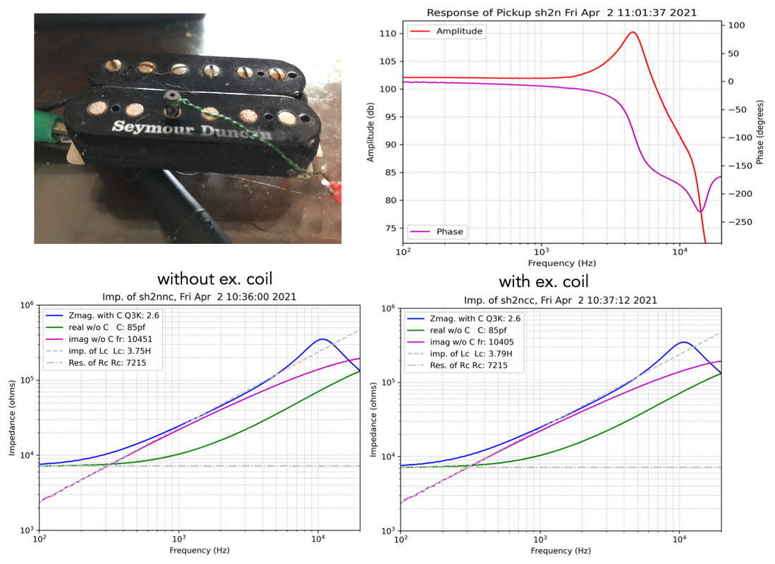 |
|
|
|
Post by ms on Mar 17, 2021 11:15:28 GMT -5
|
|
|
|
Post by ms on Mar 10, 2021 21:17:01 GMT -5
It appears that as the exciter coil is moved with respect to the slot, the Q of the resulting resonance varies. In a low Q system the frequency of the peak of the response changes as the Q varies, even if the defined resonant frequency, the boundary between inductive and capacitive, does not..
|
|
|
|
Post by ms on Mar 9, 2021 5:46:44 GMT -5
I have some designs on the Marshall forum for reactive attenuators where an air-core inductor is used to give it a varrying impedance to match that of a speaker. If you want to match the impedance of the speaker perfectly, you need some eddy current loss in your coil since the speaker coil has some such loss. The amount presumably depends on magnet material, etc. Probably not a big deal, but maybe there is no need to try to eliminate the accidental eddy currents. |
|
|
|
Post by ms on Feb 25, 2021 6:35:58 GMT -5
I think there is a limit to the localization. The current change due to the capacitance between turns a and b induces some voltages in all other turns because they are all magnetically coupled. It might be interesting to model a simple case, starting with low mutual inductance and increasing it until an effect is seen.
A single layer rf coil can be treated as a transmission line. The inductance and capacitance per unit distance determine the impedance. Its length is short compared to a quarter wavelength, and so it is capacitive, with the value computed from a very simple equation. I have read that this method works very well in many cases. I think that this works because the magnetic coupling is largest between turns that are close together, making this simple model possible.
But it does not work for a guitar pickup, a multi-layer coil with a huge number of turns. Perhaps a different approximation is possible taking advantage of a limit involving the large number of turns and the fact all the voltages resulting from magnetic coupling between turns appear in series.
|
|
|
|
Post by ms on Feb 24, 2021 12:28:01 GMT -5
I do not think that it is a anti-science to recognize what sets the overall frequency response of the system and not mess with it. Add a preamp and you can have whatever frequency response you want. This includes especially more high frequencies, almost certainly not what you want. Add a preamp and you have to include a way to keep the sound the way it was before you added it as one possibility.
Limitations in the system establish an essential part of its character, which of course you can achieve by other more complicated means if you want.
|
|
|
|
Post by ms on Feb 7, 2021 10:00:40 GMT -5
aq's model uses delay line elements to simulate the movement of a pulse on the string. The assignment here appears to approximate a delay line from each direction from the picking location using Ls and Cs; that is a kind of transmission line. You want the speed of propagation to match that of a guitar string. The L and C per unit distance determine that. So you have a little bit of playing around and simple calculation to do to get something that works.
|
|
|
|
Post by ms on Feb 3, 2021 14:22:34 GMT -5
Looks like a great meter. I like the way the display is set up. I have not located a source that will ship it to Puerto Rico, but that might happen in the future.
(Watch out for the 1832C, which does not have the higher frequencies.)
|
|
|
|
Post by ms on Dec 23, 2020 19:15:55 GMT -5
So basically, for a noob like me: Impedance is somewhat equal to the resistance at low frequencies (from what I could gather by reading up a bit). But, then the impedance increases at higher frequencies. Is there any rule of thumb on how much it increases? Does the impedance of a series humbucker increase more or less compared to the same pickup wired in parallel? Yes, the impedance of a pickup is just the winding resistance at very low frequencies. It is a resistor in series with an inductance, and the impedance of the inductor starts to matter as you go higher than the lowest guitar frequencies. The impedance of the inductor is the inductance value times the frequency times two times pi (3.14...). But the impedance of the resistor and the inductor are different kinds of quantities, and so you cannot just add them to get the total magnitude of the impedance. You have to square them, add these squares, and then take the square root. (Yes it is more complicated than we would like.) At higher frequencies, the capacitance matters, too. Antigua has a lot of plots of the frequency responses of various pickups on this site. This is controlled by these impedances. |
|
|
|
Post by ms on Dec 23, 2020 9:52:11 GMT -5
Thanks for your detailed response! Now it becomes clearer to me why the pickup in parallel tends to overpower the one in series in a dual humbucker guitar. The solution could be to run both in parallel and then filter out some of the highs (for me at least). A question though: Is the impedance of a pickup directly tied to the resistance, or are they completely independent? I noticed your estimated impedance values also match the expected resistance from a vintage tele or a dual PAF guitar. I do find it fascinating that a humbucker by itself loses output when wired in parallel, but gains perceived relative output when combined in parallel with a series humbucker. Impedance is the combination of DC and AC resistance, also stated as "resistance" and "reactance", also stated as "real" and "imaginary" resistance. DC resistance is what is obvious, the spec listed for every pickup, and then you add to that the "resistance" that comes from the inductance of the coil when the electrical signal is alternating, which can be as high as 50k ohms at the resonant peak. Let's look at this from the point of view of a meter, Extech or other. If you set it up to measure inductance, you get two numbers. One of them can be expressed as Q, D (dissipation) or R. The last is what some people mean by "ac resistance": it is related to power dissipation, but at the frequency of measurement, rather than at dc. The other number is the inductance, which is an impedance at the measurement frequency, but since the current is 90 degrees out of phase with the voltage, there is no dissipation of power, and it is better not to refer to it as a resistance, but as a reactance. For a pickup at resonance, the effect of the inductance and capacitance cancel, and the resulting high value of ac resistance can be as much as several hundred thousand ohms. But you might not measure such a high number unless you use a technique that removes (nearly) all the loading effect of the measuring instrument. |
|
|
|
Post by ms on Nov 17, 2020 5:54:37 GMT -5
All good points, thanks ! That being said if you compare the measurements to say the chopper here: guitarnuts2.proboards.com/thread/8502/dimarzio-chopper-analysis-reviewthan you can see the loaded alumitone still has a higher cutoff. I've used the chopper and it didn't have this issue at all. Admittedly the alumitone test was for a single coil version, it's possible the humbucker size measures differently but I doubt it would be drastic enough to explain the problem. Then this is a mystery! I would check the magnetic field along its length with a meter. Also measure the output from a tiny driver coil along the pickup (which should be the same even if the magnet varies). Somehow, I do not expect that this will be easy to find. |
|
|
|
Post by ms on Nov 16, 2020 6:13:39 GMT -5
Thanks for the reply ! I agree his writing is nonsense, though in practice the resistance is still lower than most other pickups including filtertrons. Good point regarding the filtering, the pickups indeed could do with more highs, but the high E is still far below the cutoff frequency of the pickups. It seems to be more an issue with the relative mass of the string compared to the others. Edit: either that or the magnetic field doesn't extend far enough but that would seem weird given that the magnet extends past the string by at least 1.5mm Perceived volume is to some extent a function of harmonic content. Have you measured relative string volumes (with careful picking), and compared to measurements made with your previous pickup? Harmonics that are low in actual power can have a significant impact on the perceived level because the ear-brain combination is very sensitive in the 2-3 KHz, or so, range. Pickup resistance is an easy measurement, but difficult to interpret. For example, a typical humbucker has high enough eddy current losses to make a significant difference in the tone near the resonance, which has a big impact on the sound. In the Lace AT you have some eddy losses, presumably, and the transformed up effect of the "coil" resistance. It would take careful measurements to separate out these effects. Edit: Antigua did his standard measurements and one conclusion was that when loaded as typical, they do not have much of a resonance peak, and thus they have quite a bit of loss. It seems to me that the loss is much higher than you would expect from the dc resistance alone. guitarnuts2.proboards.com/thread/7821/lace-alumitone-analysis-review |
|
|
|
Post by ms on Nov 15, 2020 11:40:52 GMT -5
Is it really the string volume that is less, or is it just lack of high frequencies, which affects the highest string the most? Lace avoids the issue of the spectrum of the pickup by saying that it has more bass and more mids, which is a way of saying that it has relatively less highs.
You need to look at anything Lace writes with caution. This is his basic "sell":
"This radical departure from pickup design is aluminum based, rather than copper. Result: less resistance, higher output coupled to a "current driven design" as opposed to conventional voltage based pickups.
The aluminum water jet cut exoskeleton is then matted to a micro winding using 90% less fine copper wire, a low impedance/high impedance pickup is then created."
Pure nonsense, right? Aluminum has a higher resistivity than copper. If he made that single turn coil out of copper, the pickup would have less AC resistance, not more. "Current driven design" has no meaning in this context. The coil has a very low output voltage because it has only one turn. The voltage is raised with a transformer to be similar in performance to a regular high impedance pickup. Whatever "voltage based" means, it is just like a conventional pickup in this sense. That is, they all work because of Faraday's law of magnetic induction.
I believe that the resistance he gives is just the resistance of the transformer. You need to add to this (for what counts, the total AC resistance) the resistance of the coil multiplied up by the square of the turns ratio. If the transformer has 5000 turns (it could be more), then the ratio is 25 million. So that very low resistance coil in effect is not so low.
|
|
|
|
Post by ms on Nov 8, 2020 15:50:02 GMT -5
The method I came up with several years ago is:
1. Make the dummy as near to identical to the pickup coil as possible. (This makes it easy.)
2. Make the dummy active. It feeds a FET source follower which can run on low current because it only has to swing the hum voltage, not the signal. (Although it does have to swing the signal current, but that is small for a H Z pickup.)
3. Connect the ground lead of the pickup to the source of the FET (AC coupled) instead of ground. It sees a very low impedance to ground.
So the voltage on the source is the hum voltage from the dummy coil, and it appears in series with the pickup and so it cancels the pickup hum. I forget the details, but it works fine and does not affect the sound from the pickup to a any significant degree. You do need a battery, but life is long since the current can be low. I forget how low.
|
|
|
|
Post by ms on Nov 8, 2020 5:56:31 GMT -5
It makes sense to adjust the relative number of turns for best hum rejection. As for sonic effects, the two coils are connected in series and act as a single inductor in the useful frequency range of an electric guitar.
|
|
|
|
Post by ms on Nov 2, 2020 11:47:21 GMT -5
I would divide the inductor into two that sum to the original and put a capacitor across the break. I was thinking about this model, what should the value of a "break" cap value be, approximately? Depends on where the break is and how the pickup is wound. I think that is why the effect is not observed consistently. |
|
|
|
Post by ms on Nov 2, 2020 11:45:19 GMT -5
I have a 250K with a 47 capacitor, it sounds nice but is pretty bright and shrill when out of phase, maybe going to a 22 capacitor with 250k will work since the trisonics have a lower inductance. 250K 22 cap 250k 47 cap 500k 22 cap 500k 47cap(way to bright) So many options lol To make it less bright, you need to decrease the value of resistance across the pickup. You could use a smaller value tone or volume pot, or add some fixed resistance in parallel with the pickup. |
|
|
|
Post by ms on Nov 2, 2020 11:30:35 GMT -5
You might have some capacitive coupling across the break. This would work better at high frequencies. I see. Can you show me an equivalent pickup circuit when this happens? I want to understand it better. Thank you! I would divide the inductor into two that sum to the original and put a capacitor across the break. |
|
|
|
Post by ms on Nov 2, 2020 11:25:44 GMT -5
I have a 250K with a 47 capacitor, it sounds nice but is pretty bright and shrill when out of phase, maybe going to a 22 capacitor with 250k will work since the trisonics have a lower inductance. 250K 22 cap 250k 47 cap 500k 22 cap 500k 47cap(way to bright) So many options lol Someone said it before, and I will say it again: the capacitor only matters only when the tone pot is turned down, usually well below 10. In any case, a smaller value of capacitance would be expected to not cut so much high frequencies. |
|
|
|
Post by ms on Oct 30, 2020 19:04:26 GMT -5
You might have some capacitive coupling across the break. This would work better at high frequencies.
|
|
|
|
Post by ms on Oct 8, 2020 10:33:56 GMT -5
Sensible switching for a 3 pickup Les Paul is not so easy. You have two volume and tone controls. Maybe use one pair on the bridge pickup and switch the other pair between the other two pickups. The problem is to find a lever switch that will do this. A four pole rotary, sure, but you need a small one with a long thread. But it will only feel like an original LP if it has a lever switch BR-Mid-NK. The way it is now it is just an LP with a different kind of sound in the switch position that is normally for the neck pickup, which might be the best you can easily do, although some people might prefer to connect up the middle and bridge pickups instead. You can always use push-pull switches on the pots to do almost whatever you want, but that always seems messy, non-intuitive, and complicated to me. But it would be tempting to use such a switch to go between the neck and middle with the lever switch in the "neck" or "both" positions. I've been thinking about this ever since I received the guitar. I'm thinking about having the middle and neck pickups have on/off push pulls, with the neck pickup "on" by default, and the middle pickup "off" by default, so that that it behaves like a stock Les Paul with no middle pickup, but by way of the push pulls, any parallel pickup combination can be had. I was hoping to do an "all pickups in series" option, because I think that might represent the maximum output that could be achieve by any conventional electric guitar, but it would probably sound terrible. So if you are in the normal LP mode on the bridge pickup, to switch to the middle alone, you have to move the lever switch and both push/pulls. Depending on the order of the switching, you might have all pickups off during part of the switching. All three in series might work with huge gain and distortion. After the recently deceased guitar hero, you could call it "Van Halen". |
|
|
|
Post by ms on Oct 8, 2020 7:30:22 GMT -5
Sensible switching for a 3 pickup Les Paul is not so easy. You have two volume and tone controls. Maybe use one pair on the bridge pickup and switch the other pair between the other two pickups. The problem is to find a lever switch that will do this. A four pole rotary, sure, but you need a small one with a long thread. But it will only feel like an original LP if it has a lever switch BR-Mid-NK. The way it is now it is just an LP with a different kind of sound in the switch position that is normally for the neck pickup, which might be the best you can easily do, although some people might prefer to connect up the middle and bridge pickups instead.
You can always use push-pull switches on the pots to do almost whatever you want, but that always seems messy, non-intuitive, and complicated to me. But it would be tempting to use such a switch to go between the neck and middle with the lever switch in the "neck" or "both" positions.
|
|
|
|
Post by ms on Sept 21, 2020 7:00:15 GMT -5
The plated steel pole pieces on most humbuckers and cheaper strat pickups with bar magnets below the coil seem to be a major cause of loss of Q. There is a grade of stainless steel, 430FR that is magnetic and is used for solenoid cores. It has a resistivity about 4.6 times higher than mild steel and quite high permeability. It might allow a strat pickup with adjustable poles and high Q to be made.
The magnetic and electrical properties look great. I looked around a bit for screws made from it and did not find anything. It is machinable, and so maybe you could cut a thread on a rod for adjustability. But maybe chemical and/or heat treatment is necessary afterwards. That might be a problem. |
|
|
|
Post by ms on Sept 16, 2020 17:20:34 GMT -5
What a great resource1 And I see that individual parts can be directly downloaded from that page too. I find it remarkable how the Germans seem to have embraced the technical side of guitar physics more than any other race. There are a few cases where the testing results are not completely available in the free downloads. (At least this was so a few months ago when I last looked in detail.) You had to order printed versions. I would be willing to purchase, but I would prefer electronic format; for me, a good quality computer screen is easier on the eyes than the printed page. |
|
|
|
Post by ms on Sept 8, 2020 6:50:19 GMT -5
I actually had one of the long magnet copies and built it into an archtop, but this was long before I got involved in pickup measurements. What I remember most about it was the excessively loud B string, even with the notched pole, and the extraordinary susceptibility to magnetic hum.
I would guess that the long magnets might have a marginal effect on the linearity by reducing the rate of variation of the magnetic field with distance from the active pole but they were made that size because it was the only way of maintaining a decently strong field above the pole with the available magnets while leaving the space above the strings clear. Earlier designs had partially closed the magnetic circuit above the strings. I think it was originally intended for steel guitars and the industry abandoned it as soon as better magnets became available.
It was, however, the pickup on Charlie Christian's guitar so it still has an emotional pull for many jazz guitarists who think that it has a magical sound. As ms says, appearance is probably a major part of its appeal.
It would seem that the permeability of the cobalt steel magnets is very high, although I am not sure I have found info for the right material. If so then you have the double whammy of a material with both a very weak permanent magnetic field and a very high sensitivity to stray magnetic fields. The very large pieces attached to the steel core of the winding are a very efficient hum detector. It probably was not as much of a problem when it was first used as today. There was no switching equipment at the time, such as light dimmers and switching supplies, and so you just had 60 (50) Hz and low number harmonics. The speakers then probably had not much bass, but I bet it still required careful placement of the amp to minimize the effects of its power transformer. |
|
|
|
Post by ms on Sept 7, 2020 6:39:15 GMT -5
This is a copy of a CC pickup: www.ccpickups.co.uk/about.html. If you want to put one on a Tele, you would have to do a lot of work: route a huge hole and put on a spruce top. I doubt that the huge cobalt steel magnets as opposed to normal sized AlNiCo bar magnets do much to the sound, but if you pride yourself on making faithful copies, how can you call it a CC pickup copy if it does not have the correct magnets? If you can figure out what the frequency response of the original CC pickup is, then I think you can duplicate that in a single coil pickup without either making it a non standard size or making it have the appearance of a CC. But I think the appearance is 95% of what people want, which I think agrees with Antigua's opinion.. |
|
|
|
Post by ms on Aug 11, 2020 9:49:59 GMT -5
Yeah that's something I hadn't considered. We might expect people to say "it just sounds louder", but instead we say "it sounds better". And this is yet another example of how identical pickups can result in non identical listening experiences. I think that this listening test is telling us that there are enough variables in the process that controls how an electric guitar sounds so that really small differences in the pickups are swamped by other factors. This is pointing in this direction: you can make measurements that are more sensitive to pickup differences than matter in practice. I am not saying not to measure, but rather saying that in the design process, proceed with measurements for the best way to establish differences, and then see what really matters using good listening tests. |
|