|
|
Post by ms on Feb 12, 2022 21:18:52 GMT -5
The physics tells you that the sensing width is something like a pole diameter. Why are you using 1 inch? A humbucker has two sensing regions, and that matters for measurements and for the sound on the lower three strings.
|
|
|
|
Post by ms on Feb 12, 2022 12:29:44 GMT -5
Here are three pickups in my test strat. The middle one is the one with the finished top described earlier. The other two just have the surface the printer made.
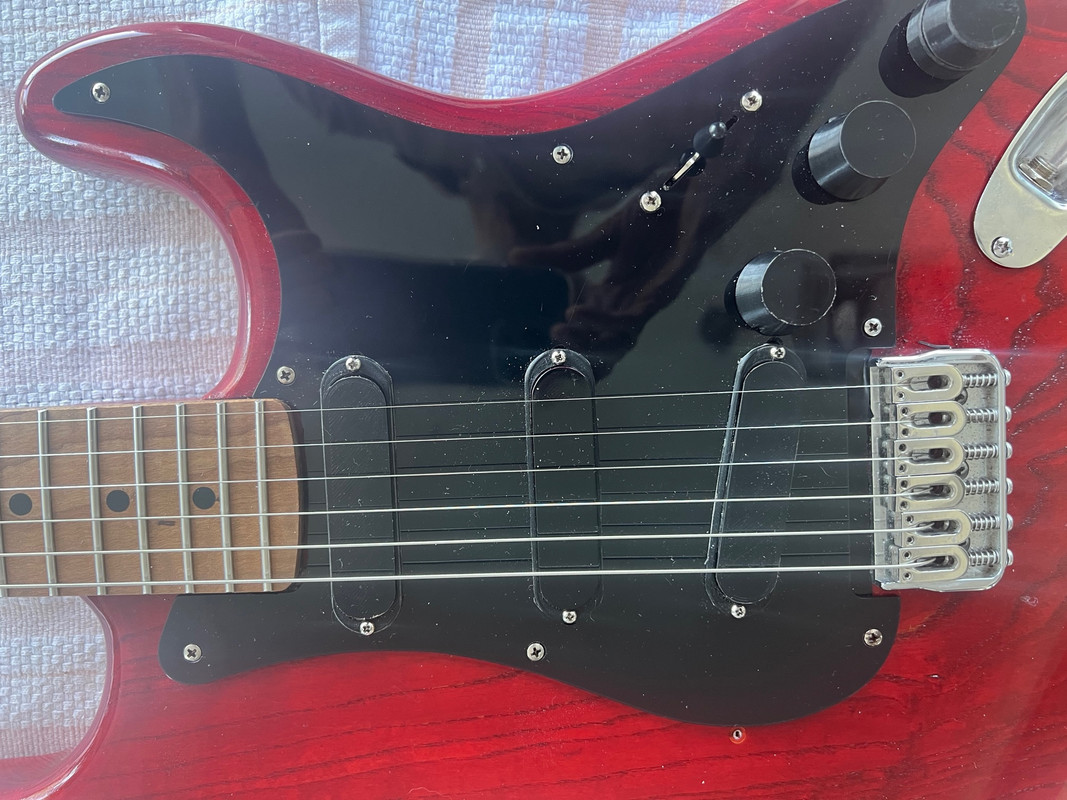
All three use #41 wire. @120 HZ: Inductance Resistance turns per coil Neck pickup: 2.49 H; 5.49 KOhms 4400 turns middle pickup: 2.79 H; 6.01 KOhms 4800 turns Bridge pickup 3.10 H; 6.41 KOhms 5100 turns On this guitar each pickup has its own tone control. (The dual shaft pot is like used on a Fender jazz bass. One element is 500K, the other 250K, but that works out OK.) I use pickup rings to help protect the windings. The Q is higher than standard, but this gives only a slightly brighter sound because the dominant damping in a strat is the circuit loading (volume control, tone control, and a lesser effect from the amp input impedance. This is well within the adjustment range of the tone controls, of course |
|
|
|
Post by ms on Feb 11, 2022 18:49:35 GMT -5
Innovative solution. So the Ferrite doesn't draw the opposing feilds down to create an area of cancellation in the middle? Suppose we have N against the face of the top coil, and S against the face of the bottom coil. The bottom coil is upside down, and so the field direction is continuous through the ferrite. This is the way I prefer to do it, but it works the other way too. This is because the field from the thin magnets decays quickly with distance, although the permeability of the ferrite extends it a bit. Remember, the purpose of the permanent field is to magnetize the strings, and we want to avoid "side effects", such as altering the permeability of the coil, or if we cannot avoid the effect, we want to cancel out its effect. |
|
|
|
Post by ms on Feb 7, 2022 18:38:48 GMT -5
Traditional materials limit the achievable performance of guitar pickups because you have to make tradeoffs among the various desirable properties. The family of pickups described in this discussion use non-traditional materials that allow a much better compromise. The technology and techniques used here allow the experienced hobbyist to make them. Fender’s construction techniques make it easy to swap or replace parts. But strat pickups are excessively narrow, constraining changes and improvements when leaving the body and pick guard in their original forms. They are noisy and low output, but have low inductance and losses, and so they have a frequency response that is very useful for some purposes. We want to make a more capable pickup for the strat and similar guitars that still fits into the pick guard and/or body rout. So we want a pickup that is hum bucking and has higher output than a traditional strat pickup, while maintaining the low inductance and low electrical losses (high Q) that enable the traditional sound. Also, we want the design of the core and bobbin to allow higher inductance (but not necessarily retaining such low losses) so that we can wind a pickup that sounds similar to a jazzmaster or P-90 pickup if we want. Why not expand the usefulness of the most available “parts” body to include all the most useful single coil pickup sounds in the same narrow format? By hum bucking we mean that it cancels hum from magnetic fields; this requires two coils, but we want string sampling like a single coil pickup in order avoid the filtering introduced by, for example, a Gibson type of side-by-side humbucker. Often a stacked design is implemented to make a hum bucking strat pickup since we have some extra space in depth but not width. So that is what we use in this design, using non-traditional materials to improve the efficiency of the magnetic circuit. The first picture shows the final prototype (meaning it is not in a guitar and can be photographed easily). The two coils are essentially identical except for connections; the bottom coil is flipped over so both coils mate with a ferrite cross piece (not visible, covered by plastic) that shortens flux return paths. With mounting in the middle and coils that are less deep than standard, the pickup can stick through the pick guard just enough. (For the strat I will show later, I use short tubing on the neck and middle pickup screws, but none on the bridge pickup, which is screwed directly to the pick guard).  Why improve the efficiency of the magnetic circuit? We have two coils instead of the single coil of a standard pickup, and so resistance and inductance might get too large. Also, although he depth of the pickup (one coil on top of the other) can be more than a standard pickup, we want to keep it less than twice. So the top coil, the signal sensor, must do more in less space, and the bottom coil should be the same thus, we need high sensitivity without making the inductance of each coil too high. This is not quite as hard as it might seem for two reasons. First, the turns near the bottom of a strat pickup contribute almost nothing to the output, but do contribute to the inductance, and so shortening the coil loses less output than you might expect, and lowers the inductance. Second, two coils phased for hum bucking in a stacked design have negative mutual inductance, and so we get less than twice the inductance of each coil when we put two in series, but we still need better magnetic material to get as much improvement as possible. So we use a material for the core with higher permeability than AlNiCo, but we cannot use steel because of the losses from eddy currents. So we need to use a ferrite, an electrical insulator, or near insulator, depending, with high permeability. Why don’t pickups in general uses ferrites for pole pieces? I think that the answer is that when decent quality ferrites became available in the 1960s, pickup design was already done, while some later “improvements” were just minor changes made to define a product. Also, really good magnets combined with ferrites make the full improvements possible. Such magnets did not become readily available until the 1980s. In this design tiny neo magnets are located on top of the ferrite, close to the strings, leaving as much room as possible for the ferrite and wire. This is useful. For example, we can use slightly larger wire so that the resistance of two coils in series is less than or equal to a standard strat pickup. I use #41 for inductances up to about 3.1 H, and 42 or 43 for higher inductance, lower Q pickups. The next attachment shows how to make a coil, and how to assemble and wire two coils. A cover is not used so that there is a bit more space for wire. The ferrite blade is thinner than the diameter of a pole piece, also leaving more space for wire. The two ferrite pieces are Amidoncorp.com part numbers DC-43-15A and DC-43-25A. The bobbins are made from a premium grade of PLA, produced on an inexpensive 3D printer. Super glue makes an extremely strong bond because it softens the surface somewhat, and so it should be applied to both surfaces before assembling them. Super glue also produces a strong bond between the pieces of ferrite, but only if they are extremely clean and the surfaces very flat. These pickups are not intended to be taken apart and repaired.  The magnets make a thin layer of magnetic material on top of the ferrite blade; that is, they are the closest element to the string. Since they are thin, the permanent field falls off quickly with distance. The field is stronger than A5 pole pieces when both are measured at the magnets, but a bit weaker at the distance I use them from the string. It is possible to adjust the field strength without changing the pickup height very much. I think I can hear a difference in the sound produced by the pickup with very small changes in the height, but I have made no serious attempt to verify this. Since the magnets have some (small) effect on the inductance (affecting core permeability), magnets are used in both the top and bottom coils to get the best match for hum bucking. If the top coil has north out of the closed face, then the bottom coil has south out of its closed face. Another reason for doing this is that there is almost no permanent field in the cross piece, assuring we have very pure single coil string sampling. I have put these pickups on two guitars; the next post will look some of the pickup characteristics. Later, a discussion will appear in the the testing and modeling sub-forum with some more detailed measurements made on a prototype. (Sometime I will clean up the freeCAD files and post them, along with the .stl files.) |
|
|
|
Post by ms on Jan 27, 2022 10:20:32 GMT -5
Consider one pole of a strat pickup with N facing upwards. The flux in the coil consists of the flux in the magnet going up and a smaller flux in the coil outside the magnet returning down. What happens if you introduce an unmagnetised string from infinity to the normal working position? The flux in the magnet increases and the returning flux decreases. There is a net gain in flux within the coil. The magnet flux increases because the space near to the magnet has a marginally lower reluctance than before so the mmf of the magnet can produce a larger flux. The return flux in the coil windings decreases because the return path including the string now has a slightly lower overall reluctance near the N pole. The lua program www.aquinaudio.co.uk/DD/plate.luawill run on any FEMM installation and illustrates this, albeit in 2D. Download and run from the bottom selection in the file menu of FEMM The results appear in the lua console which the program opens.
The plate mu is set at 10 so that it doesn't intercept too much flux. Perhaps 1.1 would better represent
the effect of a thin string. At 1.1 the increase in flux is still there but the change in the flux lines is no longer perceptible.
Yes, it runs as it should. The 5+% change in flux through the coil with a plate permeability of 10 is a bit more than I would have expected, even with a plate replacing the string, but I am sure that it is right. If you increase the plate permeability to 500, then you get a 15% change, and the plate becomes a really good magnetic shield with very low field above it. You can reduce the permeability in the y (vertical) direction to unity and still get a big effect, as one would expect from the plate geometry. What is the physical explanation? For that we have to drop a level below material permeability, which is a convenience introduced into the macroscopic Maxwell equations too allow easier mathematical solutions to problems involving magnetic materials. High permeability in a ferromagnetic material means that the tiny magnetic domains can be moved towards alignment with a small applied field. That is, it is easy to magnetize the material. Thus the physical explanation is that the system composed of magnet and plate reaches its lowest energy state when the plate becomes magnetized in such a way that the B field above the plate is almost canceled. |
|
|
|
Post by ms on Jan 27, 2022 5:51:26 GMT -5
The sensing width is somewhat wider than a pole diameter. I believe that Zollner shows this (https://www.gitec-forum-eng.de/the-book/). I am not sure that link gets you all the pdf files, but you can find them.
|
|
|
|
Post by ms on Jan 25, 2022 7:34:19 GMT -5
A point of view: while accepting the magnetised string pickup model, it is just a model. A guitar pickup is a hybrid of variable reluctance and moving magnet but for the sake of convenience it is useful to consider only the variable part of the flux and model it as a moving magnet system. If the string were made of a soft magnetic material, then the only magnetisation would be that immediately caused by its immersion in the static magnetic field. In this case we would have a pure variable reluctance pickup in which the string causes a flux change in the coil by variably re-routing a small part of the magnetic flux from the static field set up by the magnets. I think that there is a very real difference between variable reluctance and moving magnet. I do not think it has to do with whether we have a permanent magnet or not, but a lot to do with how much the flux changes around the whole path of the magnetic circuit. I think a variable reluctance system must use a "closed versus nearly closed" magnetic path with high permeability material to get enough reluctance change so that the dominant flux change through the sensing coil is the result of the flux change around the whole path. The magnetic circuit associated with the guitar pickup is nearly all high reluctance (or maybe I should say " high reluctivity" in analogy to "high resistivity"). Moving the string results in extremely little change in the field far from the string, while in a true variable reluctance system, the flux changes significantly around the whole path. |
|
|
|
Post by ms on Jan 25, 2022 7:05:12 GMT -5
The thing is that magnetic resistance happens just by having air gap, but with direct current and voltage the losses are minimal so long as the copper wires are all connected. When people think about direct current in wire, the air around the wire matters a whole lot less than air around a magnetic path. With a magnetic field, it extends though air, but when you snip a wire and create and air gap, the direct current stops flowing. There's capacitive coupling, but most people just think in terms of DC current and touching wires, imagining water in pipes. So then I suppose you have to talk about how the air in the magnetic field is like lots of resistors, and that gets more confusing than things have to be. I think that FEMM model is a good way to show someone how the string relates to the pole piece, for all the people who believe it's work is done once it magnetizes the guitar string. Yes, that is important. The ratio of high to low conductivity can be very high in typical problems, while the ratio of high to low permeability is not so high. This means that you must be very careful how you apply the analogy. It is easy to come to false conclusions. |
|
|
|
Post by ms on Jan 24, 2022 18:54:44 GMT -5
I think the reluctance model is useful when thinking about the relative voltage output of a single coil with steel poles versus AlNiCo, as was being talked about in the other ongoing thread.... The reluctance method depends on two things: 1. The same mathematical form applies to 1.) current density equals conductivity times E field and 2.) magnetic flux density (B) equals permeability times magnetic field (H). 2. The magnetic problem is equivalent to a network of resistors driven by a voltage. The first applies here, but the second does not. The plot below is of a tiny neo magnet (simulating the string, almost a simple dipole field) over a pole piece, showing two different permeabilities. It is in the cylindrical symmetry mode, and so the plots are of just the right half. When mu equals one, the pole piece does nothing. The flux falls off quickly as expected. Note that the flux is heavily clipped near the magnet; that is, we would need a lot more colors to show how strong it gets near the magnet. When mu = 500, it does not fall off so fast. So, do the plots look right for mentally replacing the small magnet with an electric dipole, replacing the spatial variation of permeability with conductivity, and getting current density instead of flux density? They do to me, and so this analogy helps me to decide that the Femm result is useful.  |
|
|
|
Post by ms on Jan 23, 2022 14:03:32 GMT -5
Hi aquin43. Another point of view: We have physics, and we have methods for solving physics problems. The physics is that the string becomes magnetized. This can be by one or more means, and the magnetization can change with time. The concept of variable reluctance is part of a method for solving certain simple problems involving magnetic materials. As you point out, it is not simple to apply to a guitar pickup. Thus the concept of variable reluctance is useful only as an analogy, not a method of solution. I think it is a dangerous analogy that can hide the physics.
|
|
|
|
Post by ms on Jan 23, 2022 9:42:25 GMT -5
Oh, I see. I was using the output of one coil as a reference. Series makes the output go up, doubling into an infinite load. Parallel with identical coils, sampling, and an infinite load should stay the same as a single coil. Parallel has lower impedance than single coil and therefore can drive a given load harder. Of course, the resonant frequency might be too high with parallel, putting the peak above the desired frequency/
|
|
|
|
Post by ms on Jan 22, 2022 12:04:25 GMT -5
The strength of the magnetic field affects the operating point on the hysteresis curve, and thus the permeability, and therefore the inductance and the resonant frequency. The Q is a function of the losses in the resonant circuit, and one factor in that is the conductivity of the pole material. But the Q has little to do directly with the permeability or the strength of the permanent field. Yes, the strength of the permanent field affects the relative levels of the string harmonics, and thus the frequency response of the instrument. (Here I am using "frequency response" in a more general way than just the response of the electronic filter made by the pickup circuit. Sorry if that is confusing.) More flux from the vibrating string through the core does not do that. (I do not think that Scott Lawing can give you a more definitive answer.) A stronger magnetic field affects how the string vibrates; that is the source of the change in harmonics. There is no analogous effect in the core. Check out his blog on pickup function. He specifically models the string flux line paths of an A5 vs higher permeability pole. There will simply be more V If more of the lines from the string pass though more of the coil. How is that controversial? I can't say if that will increase stronger vibrations more than weaker ones, but it sems like it might. Yes, there is more voltage when the relative permeability of the core increases from unity (more changing flux, more voltage: law of magnetic induction), although if you continue to increase the permeability, the increase slows down and stops. But you seem to be saying you think that when the permeability goes up the ratio of different harmonics might change. I do not think that this possible. Maybe I am misunderstanding what you mean? |
|
|
|
Post by ms on Jan 22, 2022 9:51:33 GMT -5
I am confused. If there is a significant difference in Q, you hear it. But why should there be very much difference in Q between A5 and A3? It is the conductivity of the material that matters for the Q, and I suspect that it is not all that different. I do not understand how drawing flux lines into the coil increases lower harmonic strength. Why should it have any effect on the frequency response? I think the Q of a coil is a bit lower with A2 or A3 than A5, but I don't know if permeability or Gauss is the cause. Again, the relative difference in the resonance peak is much less after it's damped by the total resistance load. It's not the freq response, but the relative difference of the stronger vs weaker string vibrations for each note that is accentuated by coil proximity. I'm speculating that roughly the same thing happens when the flux lines are pulled deeper into the coil, but it might just increase overall output for a given Gauss level. Scott Lawing might know a definitive answer. The strength of the magnetic field affects the operating point on the hysteresis curve, and thus the permeability, and therefore the inductance and the resonant frequency. The Q is a function of the losses in the resonant circuit, and one factor in that is the conductivity of the pole material. But the Q has little to do directly with the permeability or the strength of the permanent field. Yes, the strength of the permanent field affects the relative levels of the string harmonics, and thus the frequency response of the instrument. (Here I am using "frequency response" in a more general way than just the response of the electronic filter made by the pickup circuit. Sorry if that is confusing.) More flux from the vibrating string through the core does not do that. (I do not think that Scott Lawing can give you a more definitive answer.) A stronger magnetic field affects how the string vibrates; that is the source of the change in harmonics. There is no analogous effect in the core. |
|
|
|
Post by ms on Jan 22, 2022 7:17:19 GMT -5
Are you sure you have all that right? There is no doubt that a higher Q gives a brighter sound. I am not saying that a stronger field does not have do it, too by increasing harmonics. Lower permeability can lead to a brighter sound by lowering inductance and raising the resonant frequency. The Q makes much less difference when the total resistance on the pickup is factored in. There may then be less than 1dB difference in the peak of a coil going from A5 to A3, but less than half the Gauss has a big affect on how string pull affects the harmonics and how the attack hits the amp input stage. The higher permeability of A3 would only slightly increase inductance, but the affect of drawing the string flux lines down more into the coil is likely what increases lower harmonic strength. It should be akin to raising the coil closer to the string in a respect. I don't know if anyone has a definitive answer on that. I'd ask Scott. I am confused. If there is a significant difference in Q, you hear it. But why should there be very much difference in Q between A5 and A3? It is the conductivity of the material that matters for the Q, and I suspect that it is not all that different. I do not understand how drawing flux lines into the coil increases lower harmonic strength. Why should it have any effect on the frequency response? |
|
|
|
Post by ms on Jan 22, 2022 6:04:06 GMT -5
an offtopic question kind gentlemen as far as output goes parallel wiring should be like for example if humbucker in series is 16ohm parallel would be around 4 right? but that's not the only thing right (considering gauss, indurance, etc) ? so my question is does volume "technically" drops when in parallel mode ? or gainwise ? i know dumb question but ... it cuts the mids ... sounds more like p90ish like people say (never tried it myself in bridge position). well the thing is i don't like humbucker midrange at all ... so that's why i became curious about paf-ish pickups (i think lower output should push down mids a little) edit: p.s. i remember having phat cats with alnico 2 magnets ... and as i remember i hated the sound of a2 ... was too woobly, but in humbucker case my friend has gibson les paul 1960 traditional with '57 Classic Plus Pickups (a2) and that's the only les paul i like ... not a gibson guy by any means and i just found the very same donlis pickups with alnico 2 magnets ... so my another question is would it have less mids and more bottom end? by the way the model number and description is the same DHN22 which seems kinda shady but anyway here they are : www.aliexpress.com/item/32725181955.html?spm=a2g0o.store_pc_groupList.8148356.27.6ab470e8tqbl1PYeah in parallel, the output drops. The amount of voltage being produced by each coil is the same, in series it would add together, but in parallel, each coil acts as a load upon the other, dropping the overall voltage output. The funny consequence of that, is that whichever coil would be louder in series, due to having more turns of wire on it, becomes the quieter coil in parallel, because it's more loaded down by the quieter coil, than the quieter coil is of it. That's why parallel mode is about the same output as using any one of the coils alone. There's technically no mid scoop, the resonant peak just increase and adds more treble while also dropping in overall output, which people perceive as a drop in the mids. I don't think a humbucker in parallel sounds anything like P-90, they're not even technically similar. A P-90 has an inductance of around 7 henries, a parallel PAF around 2 henries, so they're on opposite ends of the spectrum. A P-90 sounds much fatter and thicker. Because a P-90 only has one coil and one row of pole pieces, it pickups up more harmonics than a PAF's two coils, and that lends it brightness a 7 henry PAF doesn't have (like a JB for example) but I don't think the tone is comparable. The P-90 picks up mids through physical means, where as a parallel PAF picks up treble through electrical means, and it's a different sound profile. If the two identical sources are put in parallel, the output should not drop. Into an infinite load, its should stay the same. When loaded, it should go up since a lower impedance source is driving the load. With hum bucking pickup coils it is a bit more complicated since they do not sample quite the same signal from the string, nor are they exactly identical. But I would not expect the output to drop much, if at all. |
|
|
|
Post by ms on Jan 22, 2022 5:56:54 GMT -5
You can find some examples of Bode plots plus a lot more relevant & accurate information from Dr. Scott Lawing on the Zexcoil site. FI, the magnetized string doesn't so much "excite" the magnetic field around the pickup as the flux lines coming from it simply oscillate through the coil. It's also not the sharper peak (higher Q) of AlNiCo V that makes it sound more snappy/brighter than AlNiCo II, III or IV, but the effect on the string harmonics from the stronger pull combined with how the lower permeability doesn't attract the flux lines as much into the coil. Scott covers all that and more in his Blog. Worth reading if you want the real story. Are you sure you have all that right? There is no doubt that a higher Q gives a brighter sound. I am not saying that a stronger field does not have do it, too by increasing harmonics. Lower permeability can lead to a brighter sound by lowering inductance and raising the resonant frequency. |
|
|
|
Post by ms on Jan 2, 2022 10:41:37 GMT -5
A regular humbucker does not reject electrical noise. You can think of this as a reversal of connections introducing two new paths which have opposite voltages across them.
How can an aluminum plate replace magnetic hum bucking? What are you trying to do with it?
If I were making a low impedance hum bucking balanced pickup, I would use a stacked or sidewinder design for single coil sampling, wind both coils with center taps, and connect the coils in parallel (so that both center taps can be grounded). Each coil should be twice the target impedance, and I would just accept some signal loss from paralleling the coils, counting this as part of the cost of obtaining very good cancellation of both magnetic and electric interference. No shielding should be necessary because of the good cancelation, but I would probably shield anyway because I think that the effect of eddy currents would be much reduced in a low impedance non-resonant design. To that end, I would make sure that the coil impedance is correct so that the load introduced by the mic input has sufficient damping so that there is no resonance peak.
|
|
|
|
Post by ms on Dec 31, 2021 19:55:05 GMT -5
The current Les Paul Recording guitar (http://legacy.gibson.com/Products/Electric-Guitars/Les-Paul/Gibson-USA/Les-Paul-Recording.aspx) uses a transformer to achieve "balanced" output at low impedance and also high impedance (presumably single ended). It is not clear whether the pickups are inherently high or low Z.
One relatively simple project would be to wind a balanced pickup that could drive a microphone input on your recording interface. Is this what you have in mind?
|
|
|
|
Post by ms on Nov 24, 2021 12:18:49 GMT -5
Heo gnuts folks Does anyone have experience in winding Pbass 5 strings pu? Typical Fender have 6 and 4 polepice per coil. This makes the coil shape uneven. When wound with the same turns, 6polepiece will result to a higher resistance and inductance. Hum cancelling will also not be perfect. If wound in such a way that dcr is same, the 6 pole output will be weaker I suppose due to less winds. What's the best solution to match them in terms of output and hum cancelling? How do Fender usually do it and how's your expwrience? This is an interesting problem for a 5 string bass. You want to keep the responses of all the strings equal, but increase the response to hum of the 4 pole coil to match the other. I would try adding some small ferrite pieces towards the back of the 4 pole coil. If this works, it would require a great deal of experimentation that would need to be done outside the bass in a test setup. In other words, this would not be a quick fix, but it might be successful with enough work. (Remember, most of the signal response comes from the part of the coil closest to the string, while the hum response comes from all along since the hum field changes slowly with distance. Therefore, magnetic material near the back of the coil away from the strings does not affect the string output very much, but does increase sensitivity to hum. Or so the theory goes!) |
|
|
|
Post by ms on Nov 17, 2021 18:20:38 GMT -5
Using your base data, I get a dead-nuts accurately matching result for actual L, being 2.922H where you measured 2.923H. I think there is something anomalous in the measured DCR value and the real DCR. The measured 6097 ohms, being in parallel with the volume pot 0f 260500, implies 6243 unloaded instead of 6327 as you measured out of circuit.  That was quick. The measurement is made at 120HZ, and so the the tone part pf the circuit has some effect, too. Not sure if this takes care of the problem, but it should do something. |
|
|
|
Post by ms on Nov 17, 2021 7:15:40 GMT -5
Let's look at the effects of varying the value of the capacitor in the calculations; that is, make the capacitor in the calculations different from that in the circuit. This is what we have with the correct values:
In [10]: getIt(2.626, 6097., 286.5e3, 255.1e3, 0.02076e-6 , 120.)
Out[10]: (2.914556831284993, 6318.391288711246)
If we make the capacitor very large (very close to shorting it out), we have:
In [11]: getIt(2.626, 6097., 286.5e3, 255.1e3, 10.e-6 , 120.)
Out[11]: (2.8798175215176367, 6352.08498429158)
Not dreadful, but a bit more error than I would like to see. Now if we make the capacitor very small (very close to just taking it out):
In [13]: getIt(2.626, 6097., 286.5e3, 255.1e3, 0.0000001e-6 , 120.)
Out[13]: (2.741306235580041, 6214.974859869338)
The inductance error is too big. Now bump up the capacitance value by about 10% over the original, and then reduce it:
In [15]: getIt(2.626, 6097., 286.5e3, 255.1e3, 1.1*0.02076e-6 , 120.)
Out[15]: (2.9124558956741238, 6321.82244457613)
In [16]: getIt(2.626, 6097., 286.5e3, 255.1e3, 0.9*0.02076e-6 , 120.)
Out[16]: (2.9168231071782236, 6314.163986064261)
Probably good enough, and so I would conclude that if it is not convenient to find out the actual value of the tone capacitor, then just use the nominal value.
|
|
|
|
Post by ms on Nov 17, 2021 6:53:06 GMT -5
Ypu is the admittance of the pickup, found by subtracting off the admittance of the resistor. Zpu is just the inverse. Then we have to interpret the imaginary part of Zpu as the inductance of the pickup. It agrees with the original measurement of the pickup alone to about 1 part in 3000. The resistance agrees to about 1 part in 2000. These are close enough to be useful. This method works to "unparallel" any impedance, the difference with my method is that I (like an LCR meter) assume that the pickup coil is just and ideal inductor & ideal resistor in series. I originally was going to make a more of a point about this, but deleted that paragraph before posting — the fact that my results differ suggests that even at 100Hz the simple series LR model the meter assumes is far enough from the truth that even the unloaded measurements are affected and thus somewhat inaccurate. For anyone else who has python installed, but not numpy (e.g. a system install), you might wish to grab pi from the math module instead, rather than installing numpy just for one constant. That's potentially where some of my error comes from, but won't account for all of it. For ±10% pot value I get a maximum of -1.7% to +1.4% variation of the calculated inductance. I also don't include the tone cap but even at 100Hz that only represents an increase in magnitude of the impedance of the tone pot of roughly 1%. It is interesting that there could be a deviation from assumed simple b behavior at 100 Hz. This might be worth quantifying ion the future. Yes math module pi is just fine. My assumption is that if you are doing any engineering or scientific calculations in Python, you want numpy there in case you want to quickly check something, and so on. |
|
|
|
Post by ms on Nov 16, 2021 7:36:32 GMT -5
So I wrote this Python code:
import numpy as np
# Invert impedance of guitar to inductance of pickup and series resistance assuming load
# consisting of volume and tone controls.
# Lm: measured inductance of guitar (pickup loaded by vo.ume and tone controls)
# Rm: measured series resistance
# Rv: resistance of volume control
# Rt: resistance of tone control
# Ct: capacitance of tone control
# fm: frequency of measurement
def getIt(Lm, Rm, Rv, Rt, Ct, fm):
Zg = Rm + ind2Zl(Lm, fm)
Zc = -1.j/Ct/2./np.pi/fm
# print('Zc: ', Zc)
Zload = 1./(1./Rv + 1./(Rt + Zc))
# print('Zload: ', Zload)
Ypu = 1./Zg - 1./Zload
Zpu = 1./Ypu
Lpu = Zpu.imag/2./np.pi/fm
return Lpu, Zpu.real
# impedance of inductance from inductance value
def ind2Zl(L, fm):
return 2.j*np.pi*fm*L
The file name is Zg2Zpu. I put a load across the pickup consisting of a volume control of 260.5K, and a tone control of 255.1K with 0.02076 microf in series. I measure 2.626H and 6.097K in series. Without the load it measures 2.923H and 6.327K in series.
I run iPython and do this:
In [1]: from Zg2Zpu import *
In [2]: getIt(2.626, 6097., 260.5e3, 255.1e3, 0.02076e-6 , 120.)
Out[2]: (2.9274282865935883, 6330.636151926141)
That is acceptable.
Next, we need to see how much the results degrade if we have some errors in the measurements of the parameters of the load.
|
|
|
|
Post by ms on Nov 15, 2021 10:53:00 GMT -5
Let's first do a test case to see how well we can "unparallel" a resistor from a pickup coil. I have here a strat-sized stacked bucker using ferrite, neo, and #41 wire. It measures 2.923H and 6.338K with an Extech at 120Hz. Next I put a 100.1K resistor in parallel and measure 2.585H and 6.004K. The meaning of "measure" is that the Extech finds the real and imaginary parts of the impedance (equivalent to amplitude and phase) and then interprets them as an inductor in series with a resistor. The first step is to "uninterpret" in order to recover Zp, the impedance of the resistor in parallel with the resistor. I do this in Python, which supports the necessary complex arithmetic, as do many languages and applications. The first line finds the impedance by converting the inductance to the magnitude of the imaginary part of the impedance using the frequency of the measurement.
In [42]: Zp = 6004. + 2.*np.pi*2.585*120.j
In [43]: R = 1.001e5
In [44]: Ypu = 1./Zp - 1./R
In [45]: Zpu = 1./Ypu
In [46]: Zpu
Out[46]: (6341.43031321018+2204.75939319565j)
In [47]: Lpu = 2204.75939319565/2./np.pi/120.
In [48]: Lpu
Out[48]: 2.924152964628128
Ypu is the admittance of the pickup, found by subtracting off the admittance of the resistor. Zpu is just the inverse. Then we have to interpret the imaginary part of Zpu as the inductance of the pickup. It agrees with the original measurement of the pickup alone to about 1 part in 3000. The resistance agrees to about 1 part in 2000. These are close enough to be useful. Next post we look at the case where we have across the pickup a volume control and a tone control in series with a capacitor.
|
|
|
|
Post by ms on Oct 31, 2021 18:46:01 GMT -5
Hi all. I’m new here and thanks for having me. I hope I’m posting in the right place. I was reading a post about building guitar pup and there was mention of a person trying to mix ferrite with neo together in 1pup. How can you mix the 2 without degaussing the neo? Im pretty sure putting lead between the 2 wouldnt shield it enough to help. Plus it wouldn’t last long because of the degaussing. I’m I missing something here. I dont have software anymore to sim it. Thanks for looking. The ferrite in question is just a highly permeable material; it has no power to degauss neo. |
|
|
|
Post by ms on Oct 22, 2021 10:37:08 GMT -5
As ashcatit said the small cap is just across the pickup when the tone control is connected, and therefore its function is to lower the resonance frequency a bit. Why would you want to do that? If it was too high, you would expect the pickup maker to wind on more turns, lowering it and increasing the output. I think the real question is why anyone uses the big cap. It has no function until the pot gets most of the way to zero and then it produces a very low resonance frequency. This makes the guitar sound sort of like a bass, and maybe in the very early days it replaced the instrument that Leo had not yet invented.
The big cap can be replaced with a resistor (10K, 20K, whatever). From 10 on down the circuit first behaves in the normal way, reducing the Q of the resonance, but then it transitions to an almost a pure LR filter. IMO, useful for setting overdrive tone.
|
|
|
|
Post by ms on Oct 21, 2021 10:02:22 GMT -5
Guys, I may have asked this a long time ago. I dunno, don’t remember; but, I’ve been strongly considering adding pickups to the things I do. And I want to get my hands on a book that describes the process of making single coil pickups. I’ve looked and am not coming up with anything very professional. I plan on buying a high quality winder, etc.; but, I know not where to start. I also need to know where I can buy materials at a reasonable cost, not StewMac prices. A lot to ask, but I figure some souls on here have gone done this road. If you want wind pickups with the intent to make things your way, then understanding how they work, as best you can with your background, is very important. Relevant chapters of Zollner's book (translated; www.gitec-forum-eng.de/the-book/) are fully understandable only with a physics and engineering background, but introductory material and conclusions are accessible. Some topics might need further explanation, so discussions here can be useful. |
|
|
|
Post by ms on Oct 18, 2021 7:19:49 GMT -5
Hello! Does anyone know what type of epoxy resin are used for pickups like EMG81 and Musicman Bass pickups? I'd like to try a repair but I'm not sure about the epoxy potting part. Not sure which solution and curing method are safe/recommended. Will appreciate if you share info or product links. Thank you! There can be thermal issues with some epoxies. Any number of places carry stuff for potting, even Walmart on line! (https://www.walmart.com/c/kp/potting-epoxy, after the first one on the list). |
|
|
|
Post by ms on Aug 31, 2021 13:08:36 GMT -5
Yeah decades of experimentation has seems to suggest that there is an optimum flux that saturates the guitar string without causing excess pull, most have a measurement of 300 to 600 guass at the pole tops, except AlNiCo 5 Strat pickups measuring over 1000 gauss. Nevertheless a lot of people like the sound of the AlNiCo 5 Strat pickup, and I suspect that is' because the harsher sound (short of causing wolf tones) in that particular context has become familiar and appreciated after years of being heard on famous recordings. On the other hand, humbuckers with ceramic magnets have not been especially popular, and historically they've not been common in recordings, so there's no reason for people to feel accustomed to, or nostalgic over, that sound. Pickups involving neodymium magnets have also fell flat in the market. So the string is saturated, or nearly so, from a field pointing along the string, resulting from the component of the field in that direction from the magnet. (A long thin piece of permeable material magnetizes much, much more easily along its axis than perpendicular to it.) The sign of the axial field flips as you move from the neck side of the pole piece to the bridge side, since the field from the magnet points in opposite directions on the two sides. This means that there is a transition region over the pole piece where the string is not saturated. aquin observed that the pickup works the same if the magnet is below the string or rotated around 90 degrees so that the field comes from the side rather than below. This means that the source of the field that makes the signal is the axial directed magnetization, which has the implied symmetry. A significant component of the field from the string perpendicular to the axis (that is, that passes through the coil along its axis) occurs only where the magnetization changes rapidly with distance, that is, centered over the pole piece. The length of the transition region should be an inverse function of the magnet field strength, but the strength of the field through the coil should be a linear function. The product of the two is roughly constant. Thus, I would expect that the output level of the pickup is nearly independent of the magnet field strength when it is strong enough to cause saturation except at or near the pole piece. |
|
|
|
Post by ms on Aug 23, 2021 12:57:39 GMT -5
It's good that there is more than one way to look at it. One way: Assume that you do not know the pot value, (Rpot = 1/Kpot), K for conductance. Then we have switch positions to determine Kn + Km + Kpot and Km + Kpot. Subtract and you get Kn. The others are found the same way from other switch positions.
|
|


