anders
Rookie Solder Flinger

Posts: 9
Likes: 1
|
Post by anders on Oct 21, 2023 19:18:51 GMT -5
Hey guys!  I'm trying to make a super strat (HSS), and I'm having some issues with the wiring. I was lucky enough to find a perfect match, on the 'Gear Page Forum', for the very specific schematic I'm looking for. Unfortunately, I wasn't smart enough to read through the rest of the thread to find out that it doesn't work. The problem I, and other people on the forum who tried it out, have is that both volume pots work in all positions. I am unable to figure out how to fix the issue and don't know if it's even possible. I was wondering if someone here has any ideas for a solution. I must admit that I'm not the best when it comes to electronics, so any form of visual help, like a schematic, would be greatly appreciated. But all help is, of course, more than welcome. This is what I'm tryinng to do: - Two Volume (250k Neck/Middle+500k Bridge) - One Tone (250k 47uF Neck/Middle) - Auto split the humbucker in postion 2 - Treble bleed for both volumes - Im using an (OAK 5 WAY LEVER SWITCH DOUBLE WAFER (OUTSIDE TERMINALS)) This is the Scematic I tried to use (top one) 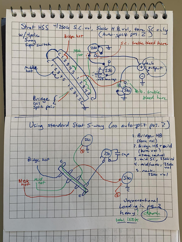 |
|
|
|
Post by newey on Oct 22, 2023 7:54:50 GMT -5
anders- Hello and Welcome to G-Nutz2!A couple of issues here. First off, the diagram that you didn't build, the one with the standard Strat 5-way, has no output from the common lugs so there would be no sound. It may be that the author of that just didn't include that connection as being assumed, but the diagram is incomplete as it is. With the 4-pole Superswitch version that you did build, because both volume pots are connected to the output jack at all times, they are wired together in parallel at all switch settings, and you will have both volumes at all times. The solution is to wire the output jack + to the common lug of the lower right-hand pole of the Superswitch instead of wiring it off the pots. But there is a better way: JohnH's Strat With 2 Volume ControlsFirst off, you can see what I mean about your wiring if you look at the first diagram JohnH has in that thread. See how the jack tip is connected to the commons of the 5-way? Second, JohnH's version also has a dual-gang pot for the master tone control, giving you a tone control for all 3 pickups. A "dual gang" pot is simply 2 pot elements mounted on a single shaft, so turning the knob moves both pot elements. John's HSS has some other bells and whistles which you may not want to implement, but a HSS version of his idea could be easily worked out so as to give the coil cut in position 2 on the HB. Also, it is probably possible to use a regular 5-way switch to do the "auto-split" at position 2. Fender's "Fat Strat HSS" guitars did this by moving the tone control wiring to the pickup side of the 5-way, and using the middle lug of the other pole to ground the HB series connection at position 2. But I'm not sure if that could be worked out given the 2 volumes. In any event, JohnH's thread above is required reading . . .
|
|
anders
Rookie Solder Flinger

Posts: 9
Likes: 1
|
Post by anders on Oct 22, 2023 12:19:45 GMT -5
Thanks for the response.  I'm not sure about the bottom diagram, but fortunately, no one tried to use it as far as I know. And the original author has since taken it down from the forum to avoid confusing any more people. It makes a lot of sense that wiring both volumes together in parallel would have them work all the time. But if I wire the (jack out) to the common lug, then where should I add the 'output' lugs from the volume pots if the rest of the wiring is exactly as shown in the diagram? I've also looked at the thread you referenced, and I'm having a hard time translating the 'regular five Fender switch' to the '4-pole superswitch.' I think I'm lacking some understanding of how the two switches work. Also, I rarely/never use the tone control for the bridge, so having it work for only the neck/middle isn't an issue.  |
|
|
|
Post by newey on Oct 22, 2023 16:07:44 GMT -5
Let's use JohnH's diagram from the link I posted as an example. I used a yellow highlighter on the signal path for the bridge pickup and Bridge volume. Obviously, your diagram will be different with the N/M tone. So ignore the tone controls in JohnH's diagram, and ignore the trable bleeds (the cap/resistor combo across each of the volume pots); just follow the signal path. You'll see how the bridge pickup "hot" wire goes to the Vol pot first, then to the 5-way switch lug #1. With the 5-way switch in positions 1 or 2, lug #1 is connected to the common lug, which is connected to the jack tip. That all happens on one pole of the switch, the other pole is used to switch the neck and mid pickups. 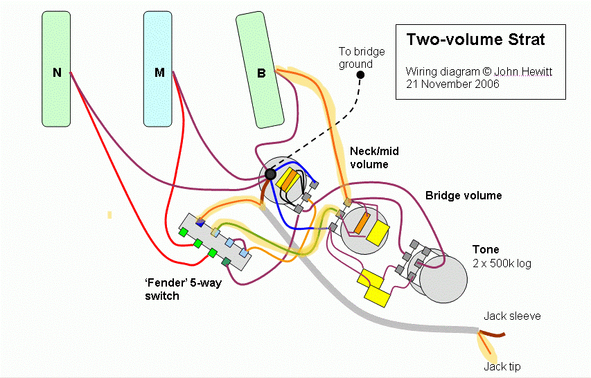 For the neck and mid pickups, it's a bit different. They get their hot wires connected to lugs 2 and 3 of the 5-way, and the common lug then goes to their shared volume pot. The "hot" output from the V pot then goes back to the 5-way, lugs 2 and 3, which then get connected to the jack tip in those positions of the switch. Now, on to your needs here. This is undoubtedly the crudest drawing I have done 'round here, but in a bit of a rush today. I hope you can follow it. Probably best if you redraw it just to be sure you're reading it right, and that'll give someone else a chance to check my work just to be sure. But this should work. You will have all 3 pots in play at position 2, that's just the nature of the beast. 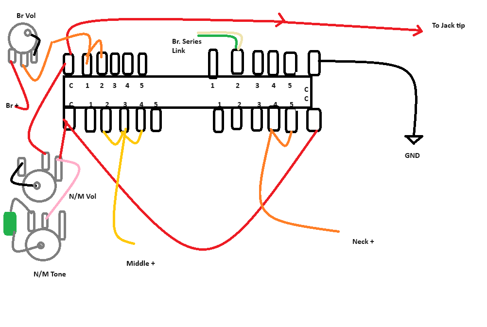 |
|
|
|
Post by sumgai on Oct 23, 2023 12:02:57 GMT -5
anders , Hi, and  to The NutzHouse!  The diagrams you posted both suffer from having the two volume pots connected directly to the output jack - that's why both Vol pots control the output level regardless of where the pup selector sits. Technically speaking, this could easily be rectified by merely reversing the Vol pot connections - what we call "backwards wiring". In fact, such a scheme is common for guitars like the Les Paul, the SG, and a myriad of other copy-cat guitars. This is used where a player might want to significantly reduce the volume level of only one pickup when there is a combination going on (a poor man's blend control, so to speak). It means that one pot won't be able to kill the entire signal, but the drawbacks are numerous. I suggest you use Search from the menu above, if you're curious. newey is correct in showing you how these things are assembled together so that it all works as (most) players expect - signal from the pickup to the Volume pot first, then to the switch, then to the output jack. (Ignoring the Tone control for a moment.) However, do take note that in his admittedly rushed diagram, the Neck and Middle pups are not heard when not selected, but the N/M pots are still connected directly to the output jack, so they will control the output signal at all times. Essentially, it looks like he ignored his own advice and put the switch first for those two pickups, but in actuality, he simply forgot to show you the rest of the switching arrangement. Not his usual kind of mistake, I assure you. Instead of providing a corrected diagram for you, I'm going to suggest that you take his advice and redraw the whole thing yourself. But now I'll caution you that I'm giving you a test that won't be easy to pass!    Even given the clues I just mentioned, this will require some thinking "outside of the box". Post whatever you come up with, and we'll vet it for you.  HTH sumgai
|
|
|
|
Post by newey on Oct 23, 2023 14:00:35 GMT -5
anders- Yeah, sg is right, I rushed the drawing. But you should try to redraft it as he suggested, and as I suggested as well.
|
|
anders
Rookie Solder Flinger

Posts: 9
Likes: 1
|
Post by anders on Oct 23, 2023 23:39:51 GMT -5
Thank you so much, both of you, for all of the advice!  I'm currently trying to redraw the schematic as you suggested and will be posting as soon as I have something I think might work. |
|
|
|
Post by sumgai on Oct 24, 2023 10:38:49 GMT -5
Take your time, we're not going anywhere in the foreseeable future.  |
|
anders
Rookie Solder Flinger

Posts: 9
Likes: 1
|
Post by anders on Oct 25, 2023 0:16:09 GMT -5
I've now redrawn the schematic, and I think I actually understand how it works now. But that being said, the only thing I could come up with is connecting the output of the 250k volume to lug 234. But I'm pretty sure it has the exact same problem as it did before, due to lugs 1 and 2 being jumpered. Am I on the right track? 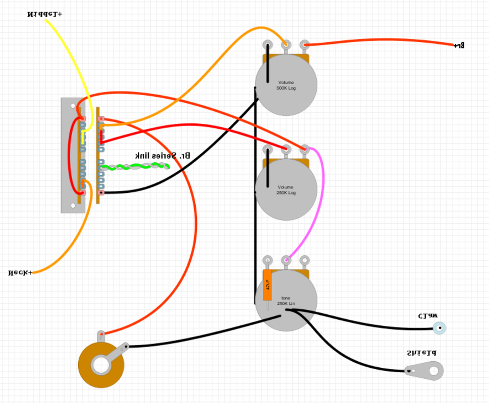
Or maybe something like this 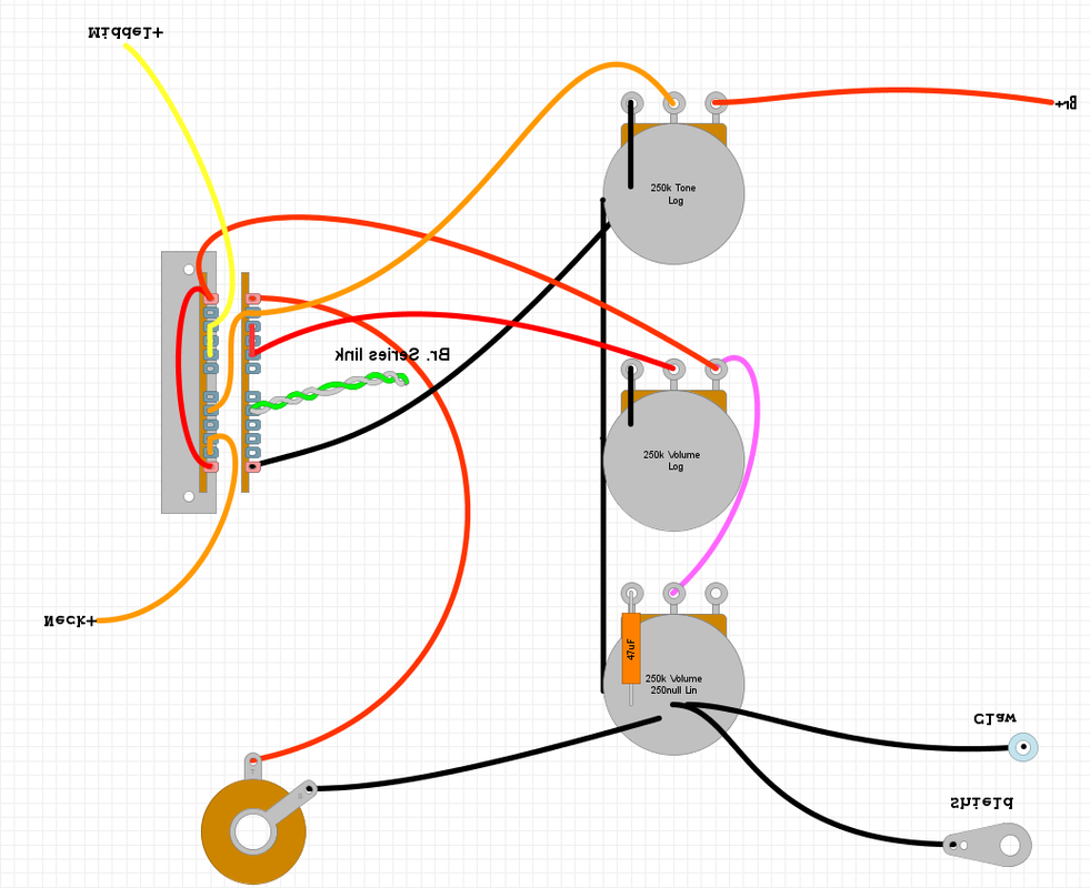 |
|
|
|
Post by sumgai on Oct 25, 2023 12:38:23 GMT -5
anders , You're actually getting closer than I had imagined you might on your first outing. So you're on "sort of" the right track, which earns you a clue: The link that selects 'auto-split' in Position 2 does not need to go to ground, it can go to Hot just as easily. (More on that in a moment.) Now, looking at that idea, you can move the link to some other pole of the SuperSwitch, thus freeing up a pole for use as a control to switch in or out the Neck/Middle pickups and their controls. Run with that, and see what you get. (And please don't reverse or flip portions of the image, reading those labels made my brain hurt.  ) As to the effect of splitting the humbucker, you need to pay attention to the following: 1) Polarity, as in hum is either reduced or enhanced. This can be easily solved. 2) Tonality of the selected coil. The coils (properly speaking, their magnetic fields) are so close to the end of the string as to make no practical difference in the resulting tonality. It is my opinion, but not necessarily that of other Nutz, that when combing either coil with another pickup, the resulting tones will be indistinguishable from each other, especially in a live gig setting. For that reason, hum cancelling should be your primary concern. If you truly want to have the selected coil nearest to the bridge but it now hums, you can simply rotate the entire pickup. Yes, it's that easy. Don't get into slug versus screw, that's a vanishingly small difference, and only an OCD-class individual will want to invest that kind of time and effort for so little return. Best to get on with the assembly, and get back to playing that much sooner.  HTH sumgai
|
|
anders
Rookie Solder Flinger

Posts: 9
Likes: 1
|
Post by anders on Oct 25, 2023 23:44:38 GMT -5
I see how freeing another pole would solve my issues, but I don't think I quite understand how the auto split works. I thought it worked by grounding out one of the coils, thus eliminating it from the circuit? If I could get a clue as to what the faults of the circuit I drew would be, and maybe an explanation of how the auto split works, I think I might be able to figure it out. And when it comes to the labels, I use the DIY Layout Creator, which mirrors the labels as a default, without any way of changing it...  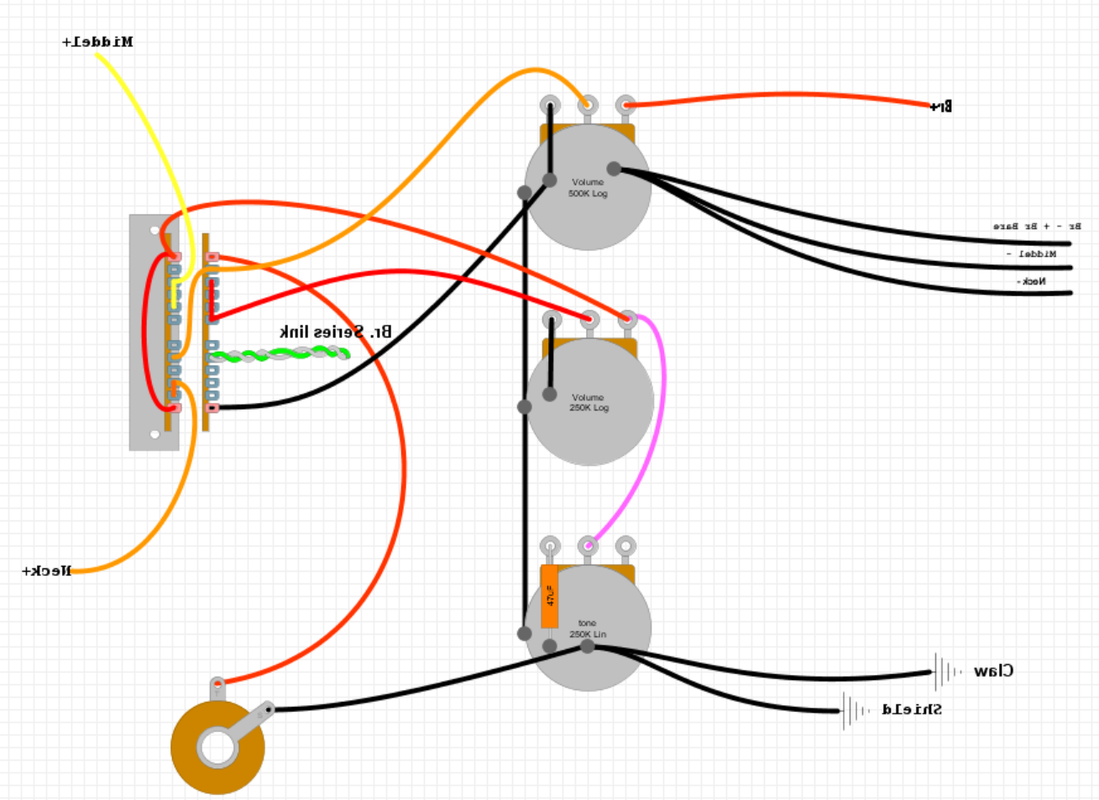 |
|
|
|
Post by newey on Oct 26, 2023 5:07:16 GMT -5
but I don't think I quite understand how the auto split works. I thought it worked by grounding out one of the coils, thus eliminating it from the circuit? So, a brief primer on splitting coils. I'll use Seymour Duncan wire colors as the example, since you didn't specify the pickups you are using, and I don't know if your latest diagram is using the actual colors of your HB's wires. For an SD pickup, the color scheme is that the N coil is the black and white wires, the S coil is the green/red pair. In typical wiring, the black is the "hot" output, the green is the ground, and the blackred/white pair form the "series junction" between the 2 coils. If one is not splitting the coils of the HB, the white/red pair is simply wired together and not attached to anything except each other. If we want to split the coils, we can (as your diagram shows) ground the series junction wires. When we do so, the black wire is still connected to the output, the white wire is now grounded, the red wire and green wires controlling the S coil are both grounded. So, the N coil is still connected to output via the black wire, but the white wire is now grounded, so we hear the N coil. Both ends of the S coil are grounded, shorting that coil to itself and we don't hear it. Thus, if we want to split an SD pickup to the N coil, we ground the series junction. But what if we want the S coil to be the operable one instead? Easy enough, now we simply wire the series junction to the hot ouput instead of grounding it. Thus, the black wire is still connected to the output, but now so is the white wire. The north coil is now shorted to itself and we don't hear it. The S coil now has the red wire connected to the hot output, the green wire remains grounded, so we hear the S coil only. So, what sumgai is suggesting is that, if you want to auto-split the HB at position 2, you can wire the series junction to ground, as your diagram shows, but you could also split the coils by wiring that series junction to the hot output- it just splits it to the other coil instead. As he says too, if it matters to you which coil is the active one, inward or outward, you can just rotate the pickup 180°. But, particularly at the bridge position (and assuming the HB has 2 identical coils) which coil is active won't make a big tonal difference. More useful is to pick the coil so as to have hum-cancelling with one or more other pickups- we can help with this but we'd need to know more info about your pickups- coils, wire colors, polarity- to sort that out for you. And, as sg also notes, you have empty lugs at position 2 on one or more of the poles of your superswitch which are already connected to the hot output . . . Now, to complete the thought on splitting a HB. In some wiring schemes, we may want to split to a particular coil but, because of other aspects of a particular scheme, be unable to wire that series junction to the hot output without messing up other parts of the scheme. If so, we can also wire a HB "inside out" (as our member wolf terms it) to split to the other coil. To do so, again using my SD example, we wire the white wire to the hot output instead of the black, and make the red wire the ground instead of the green. The green/black pair now becomes the series junction. Wiring that junction to ground, instead of giving the N coil as above, now gives us the S coil instead- the N coil is now grounded to itself. But in your scheme, you can just split the coils the "easy way" without wiring the HB "inside out". But, if getting the N versus S matters as to the hum-cancelling, the opposite coil can be the split one by wiring the pickup in the opposite fashion as described. Hope that helps! |
|
anders
Rookie Solder Flinger

Posts: 9
Likes: 1
|
Post by anders on Oct 26, 2023 7:49:05 GMT -5
Ah, I see. If both sides of a coil is going to the output, it has the same effect as if both are going to ground, of course. Would this work, then? 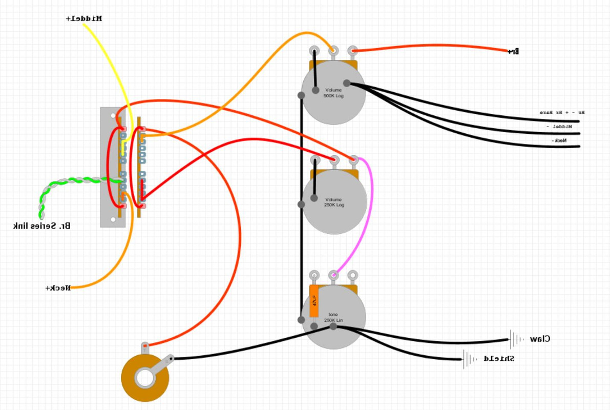 Or maybe just like this, so as not to have the bridge series link go through the 250k volume control. 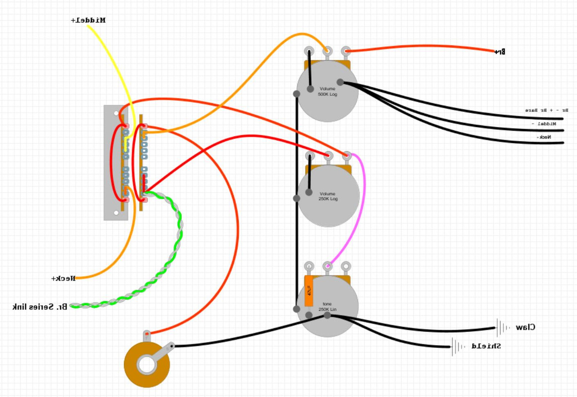 |
|
|
|
Post by sumgai on Oct 26, 2023 11:48:14 GMT -5
If I could get a clue as to what the faults of the circuit I drew would be, and maybe an explanation of how the auto split works, I think I might be able to figure it out. has covered the auto-split portion, and we've both given you the low-down on the fault of your original diagrams - that being, both Vol pots go to the output jack. Here's how that plays out, to your detriment: Imagine an output jack with a resistor (a plain, ordinary, garden variety resistor) connected from the tip to ground. If that resistor is a small value, it will greatly interfere with the signal, but if it's a large value, then it won't do too much damage to the signal at all. Now, imagine that this resistor can be changed in value, from a high value to a low value. This variable resistor is our Volume pot, and it's physically connected at all times. By turning down the amount of resistance to zero (or very nearly zero), we are shorting the tip of the jack straight to ground, aren't we? And that happens regardless of whether a signal is actually passing through the pot, what counts is the fact that the pot is connected in that manner in the first place. Does all that make sense? Good. So the net effect is that we don't want Neck/Middle Vol pot to work when in Bridge only mode (Position 1). To do that, we need to control when the N/M Vol pot is going to the output jack, don't we. And that requires the fourth pole of the SuperSwitch. (The upper-right, in your provided diagram.) And that's why I said we can change the series link (the auto-split) from ground to the hot line - the effect is the same, we get one coil instead of both, as explained in detail by newey . And as he also explained, we can now move that N/M pot-controlling sub-system to somewhere that already has a hot connection on the common terminal. Now, in a post above, I alluded to your using three terminals to get somewhere close to the objective. I think you can now see that if you connect the N/M Vol pot to Positions 2, 3, 4 and 5 of the upper-right pole, and the common to the hot line, you will be controlling the N/M pot so that it is on in Positions 2, 3, 4 and 5, and off in Pos 1. Et Voila, goal achieved! And at no additional cost in parts, only a few wires moved around - how neat is that?  Simple, eh?  HTH sumgai |
|
|
|
Post by newey on Oct 26, 2023 12:17:35 GMT -5
Your first diagram looks good to me, but let's get a second opinion before you begin surgery.
No, sorry, the second diagram is not correct, as it shows the series junction going to lug #5 instead of lug #2, which is what you need to get the coil split with the B + M setting. But you are also thinking about this wrong. At position 2, the M and Br pickups are on in parallel with each other. Given that, you can't avoid having both volume controls (and the tone, as well) in the circuit- they're all connected together at that setting anyway you slice it. SO, you really only have 2 choices here: First, you could just learn to live with the 2 duelling volumes (and one tone) at position 2. This would really be no different (ignoring any differences in pot values) than the situation with any LP-style guitar with separate V and T pots, when both pickups are selected (i.e., center position on the 3-way toggle on an LP). Yes, the controls will interact, but people have been playing (and in many cases, fanatically loving) their LPs for years with complaint. The dulling of the tone by having 3 pots in the circuit won't be any worse than what Strat players encounter at position 4, when all 3 pots are in the circuit- and the Strat guys don't seem to mind that much, either.
Option number 2 would be to disconnect the N/M V and T pots at position 2. This would just leave you with the Br V pot only at that position, avoiding both the extra loading and the control interaction. But then of course you can't control the Mid V or T at position 2. Before you, or anyone, says they don't care about losing those controls, keep in mind that splitting the bridge to a single may result in a mismatch of output with the middle pickup- and you wouldn't then be able to reduce the middle to match the bridge. If you wanted only a single control at #2, it would be better to lose the N/M vol and Tone, keeping the Bridge Volume- but that would mean a complete rethink of this scheme
|
|
|
|
Post by Yogi B on Oct 26, 2023 13:30:39 GMT -5
that's why I said we can change the series link (the auto-split) from ground to the hot line There's only one place on the "hot line" that would unconditionally shunt the 'upper' bridge coil: the bridge hot wire / terminal 3 of the bridge volume pot — notably connection which is not currently involved in any switching! Any other 'hot' would be fine with both volumes fixed at 10 — however, when reduced they would introduce series resistance to what ought to be a direct short, leading to all sorts of weird behaviour. The best way I can currently see that this scheme could be made to work (with the available switch) is to remove the permanent connection between neck pickup 'minus' and ground, and instead have the neck pickup 'plus' permanently hang from lug 3 of the M+N volume pot. Then we can use just one pole of the super switch to ground the neck 'minus' in positions 4 & 5, the bridge series link in position 2 & bridge 'minus' in position 1. This will leave the neck 'hanging from hot' in position 3, but I don't see a better alternative. And when it comes to the labels, I use the DIY Layout Creator, which mirrors the labels as a default, without any way of changing it...  I don't know what version of DIY-LC you have but the latest ( v4.37.0) has normal (non-mirrored) labels in addition to mirrored "PCB Text", both under the "Misc" category. However, the "Common Node" object (also in the same category) seems a better fit for the purpose of labelling connections. |
|
|
|
Post by sumgai on Oct 26, 2023 15:36:40 GMT -5
anders , Yogi B is correct, in my version of the circuit, the "shorted" coil will indeed be brought back into play as you reduce the volume of the N/M knob. In point of fact, at the lowest volume (N/M completely off), it will "choose" the other coil! This is because the series link is no longer pointing to the hot line, instead it is grounded. Following the signal path, that means that we've shorted the desired coil, and unshorted the remaining coil - it now sounds out. Not quite what we wanted. Now to be fair, I did anticipate this. It is my observation, over the years, that most players don't blend two volume controls by twisting one more than about 30% or perhaps 40%. Effectively, the pickup remaining at full volume simply swamps the reduced pickup, and that's not doing anything for one's tone. However, even at this small of a reduction, the no-longer-shorted coil is now in play, and will likely contribute some small amount of signal to the overall mix. (And remember, we're speaking only about the combo in Position 2, none of the other positions will suffer this malady.) What I've just described can only be named "dial-an-unsplit". (Search on "dial-a-split" to see what I mean.) So what I "forgot" about, and I have to admit that I ignored it, is that at the point where the pot is showing equal resistance to both halves (i.e. it's about 50% of the total resistance on each leg (regardless of taper)), the two coils of the Hb will be in series, but each coil will be in parallel with their associated resistances. The final result will be that the Bridge pup will sound out at a much reduced volume. This is because in Pos. 2, both Vol pots are in the circuit, so regardless of where the Bridge volume sits, the N/M Volume pot will control everything, just as it did before, when you first started this thread. Not a nice result. Yogi's suggestion of having a hanging hot for the Neck pup 'hot' and controlling the Neck minus lead is not a bad one. If you understood what he meant by that, then try to draw out a new diagram incorporating that suggestion. The reason I did not go for it is that it involves much more wire moving-around, thus increasing the risk of errors creeping in. But the idea has merit, and it's worth testing for yourself. (Actually, Yogi is rarely wrong when it comes to circuit design, so forge ahead with full confidence.) HTH sumgai
|
|
anders
Rookie Solder Flinger

Posts: 9
Likes: 1
|
Post by anders on Oct 26, 2023 23:55:25 GMT -5
Thanks for all of the input!  This is also sort of what I meant by not wanting the series link to go through the 250k volume pot, as it would control which coil is shorted. But I didn't realize that in my second diagram, I was just moving it to the other side of the pot and thereby not changing anything. I've tried to incorporate all of Yogi's input, and this is what I could come up with: 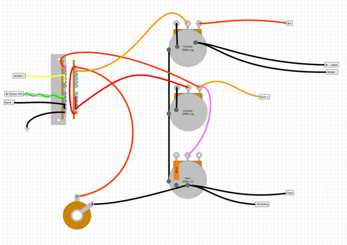 |
|
|
|
Post by unreg on Oct 27, 2023 15:29:54 GMT -5
I've tried to incorporate all of Yogi's input, and this is what I could come up with:  hi anders, You seem to be grounding middle pickup on 500K vol case, then 250K vol pot is grounded to itself. That ground path travels to your tone pot case, where it seems to be accepting a shield ground. Pickups and pots are signal grounds, and signal grounds should be kept separate from shield grounds until the jack’s ground; at least the two shouldn’t be combined on the electronics. That combination of signal and shield grounds on your tone pot is sure to create noise. And, the middle pickup ground relies on a solder spot on both vol pot cases and the tone pot case; so, if you implement this diagram, be sure to solder those spots perfectly.  If you choose to implement a “star ground”, that would be beneficial if you want your guitar to not produce noise. If you just keep your signal and shield grounds separate until the jack’s ground, that could be perfectly ok too. 👍 I just used a star ground bc that seemed easier to me. (A star ground can be any conductive piece not currently in your circuit, like a washer or a paperclip. All grounding wires are soldered to a star ground, including the most important jack grounding wire.) EDIT: perfectly doesn’t mean lots of heat or lots of solder. Newer pots are made from cheaper materials; their insides are more prone to being ruined by heat. Another benefit of star ground is being kinder to your pots. Noise does also happen if their insides melt a bit… don’t ask me how I know this.  |
|
anders
Rookie Solder Flinger

Posts: 9
Likes: 1
|
Post by anders on Oct 28, 2023 10:21:54 GMT -5
I had no idea that ground placement had any effect on noise. Good to know.  I'm guessing something like this might be better then? 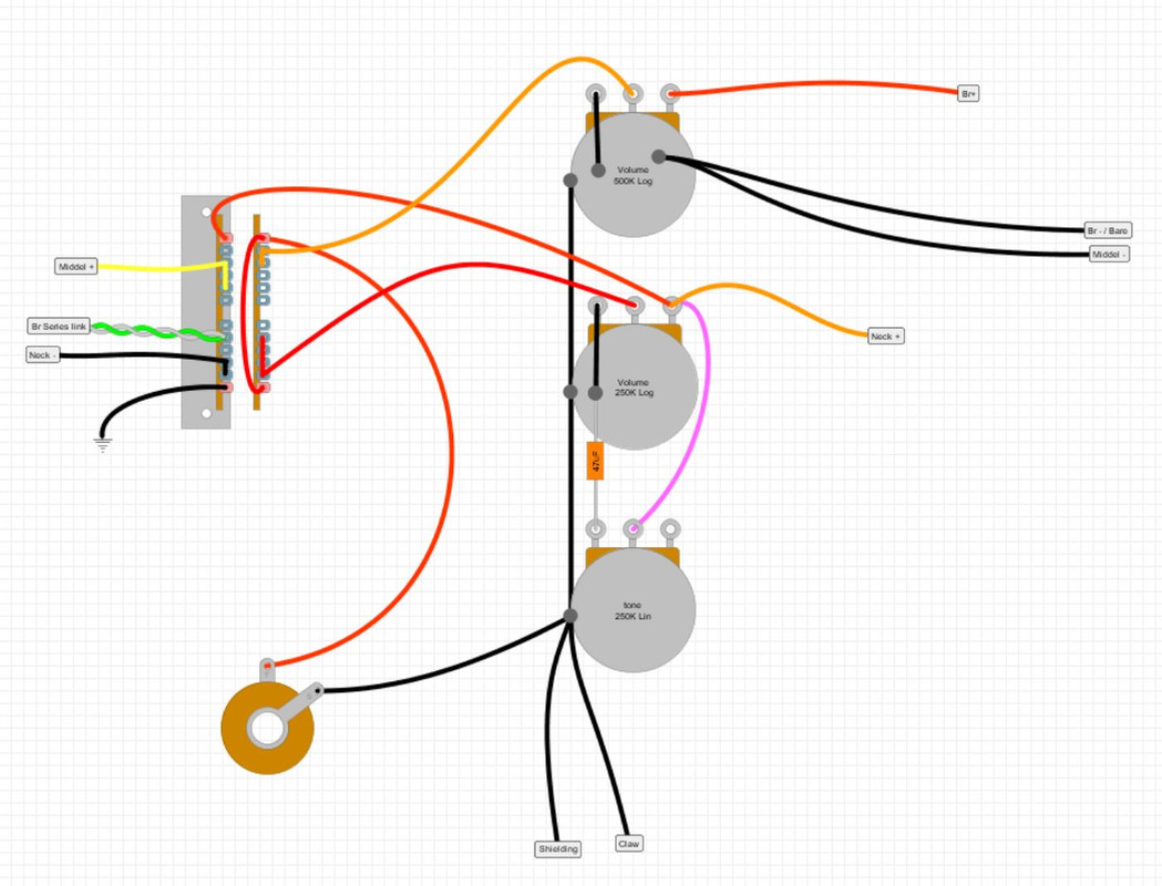 I'll do my best when soldering, but I'm not the most experienced, so I can't promise anything. Is the schematic otherwise okay to try and implement?" |
|
|
|
Post by sumgai on Oct 28, 2023 13:05:37 GMT -5
anders , Well, that didn't take long, nor too many 'updates' - you're golden!  Between the four of us ( newey , Yogi B , unreg and myself), you've managed to successfully design a circuit that will fit your desires. Now all you need to do is put it together physically. However..... the bit about grounding. You show (again) the several ground points for both signal and noise abatement as being mixed on the back of pots. For all the pickup minuses (the Neck being switched), you should take those leads directly to the output jack's ground terminal, and not to the back of any of the pots. That will truly isolate as much as possible the signal grounds from the noise shielding grounds. We call that a "best practice". HTH sumgai
|
|
|
|
Post by unreg on Oct 28, 2023 13:48:28 GMT -5
Ahhgh, have to write this again… will try… …show (again) the several ground points for both signal and noise abatement as being mixed on the back of pots. For all the pickup minuses (the Neck being switched), you should take those leads directly to the output jack's ground terminal, and not to the back of any of the pots. That will truly isolate as much as possible the signal grounds from the noise shielding grounds. We call that a "best practice". HTH sumgai Maybe I’m confused… but, it seems, from past advice/instruction given AND personal experience following that crucial instruction, that we should keep signal and shield grounds separate until the jack’s ground. Sir sumgai, if anders moves all pickup minuses over to the jack’s ground, won’t he still be mixing signal with shield grounds since, grounding a pot to itself is signal ground and those signal grounds are meeting shield ground still on the back of his tone pot? Ok, I bet I missed something, but I don’t want to retype this again.  |
|
|
|
Post by newey on Oct 29, 2023 7:14:04 GMT -5
unreg- First off, none of this is "crucial", as sumgai said, it's a "best practices" thing. The possibility of extra noise being introduced is just that, only a possibility (and probably a long odds situation most of the time). won’t he still be mixing signal with shield grounds since, grounding a pot to itself is signal ground Not really. The latest diagram above shows the Br - connection going to the pot. I'd move that ground over to the common lug of the 5-way switch, where the neck - is connected, but I wouldn't worry about the pots being grounded to each other or about the third lugs of the pots being grounded to the shells. If one were to implement a star-grounding scheme, it would be different. And it is helpful to avoid too much soldering to the backs of pots (which a star ground does). But there's nothing inherently "noisy" in doing it as shown above.
|
|
|
|
Post by unreg on Oct 29, 2023 7:16:51 GMT -5
For all the pickup minuses (the Neck being switched), you should take those leads directly to the output jack's ground terminal, and not to the back of any of the pots. That will truly isolate as much as possible the signal grounds from the noise shielding grounds. We call that a "best practice". HTH sumgai Ah, yes… I did miss sumgai’s boldened-by-me text. I’m sorry for my distressing post. |
|
|
|
Post by sumgai on Oct 29, 2023 11:47:27 GMT -5
unreg As it happens, there's a definition of separate grounding, and it boils down to simply isolating the signal grounds from the shielding grounds for as long as possible. What John Atchley did (you remember him, the original GuitarNuts operator) was to use a washer as a localized point of contact, and then run a single wire from there to the output jack sleeve. In fact, it makes no difference if you use that intermediate point or not, the idea of the effect is the same - isolation. newey says 'use the common terminal where the N- is connected', and that's just as good as any other method of centralizing a bunch of connections headed for the jack sleeve. I do agree, running wires all over creation is messy, and can be difficult to diagnose when problems arise. But the other side of that coin is an increased risk of poor or bad solder joints if too many wires are hooked together at one terminal - thus the idea of a washer. Nice and large, lots of room for individual wires to get soldered on to it without the increased likelyhood of disturbing other connections. In short, it all depends on one's proclivities - make it work for you, as you see fit. We're only suggesting guidelines. --------- Now to speak to the idea of 'back of the pot' grounding. As it happens, the problem of overheating the back of the pot and causing internal damage is only one factor in the discussion. The other is that by doing so, we're depending on the mechanical connection between that pot back and any shielding that the pot contacts when mounted. I'm speaking of copper foil, tape, paint, whatever. So long as it's supposed to shield the components from external interference (hum), then depending on it to do anything else, such as carry signal ground from the pickups, is folly. It may work, and it may do so without noise, but that's not a "best practice", that's simply being lazy. In my book of course, others may feel differently about it. But if it's folly as I suggest, then one needs to ask a tough question: just why did John A. start up his own website in the first place, with the singular goal of curing the hum problem for good? And lastly, if you open up a quality guitar, you find that the pot backs are hooked together with soldered wires, they don't necessarily depend on contact via the mounting point, etc. That's because they're bending over the third terminal and soldering that to the pot back.  I've never done that, I've always used a wire to get from there to a common ground point. But a big exception would be that when I was in the repair business, I'd leave a customer's guitar alone, unless it came in with a complaint about hum or noise - then I'd revise it to my standards. IOW, I didn't fix what the customer didn't claim was broken.  HTH sumgai
|
|
anders
Rookie Solder Flinger

Posts: 9
Likes: 1
|
Post by anders on Nov 1, 2023 12:31:09 GMT -5
Just wired it up, and it works perfectly!! And with minimal noise. Thanks to all of you for the help. What an amazing forum with great people  |
|
|
|
Post by sumgai on Nov 2, 2023 11:39:15 GMT -5
Just wired it up, and it works perfectly!! And with minimal noise. Congratulations! This is exactly what The NutzHouse is all about, no exceptions. Stick around, you'll soon find yourself offering help to other newcomers!  sumgai |
|