|
|
Post by JohnH on Sept 6, 2020 18:28:13 GMT -5
JohnH have you posted your update schematic? Sorry I haven't. I intend to do it, but itz been more a bucket-list objective than an urgent item high on the 2-do list. If theres interest I can raise it up. |
|
|
|
Post by neophytebuilder on Sept 6, 2020 19:30:03 GMT -5
JohnHI am looking to build it in October :-)
|
|
|
|
Post by neophytebuilder on Sept 7, 2020 8:47:25 GMT -5
JohnHI can see where the 220k resistors need to be dropped down to 150k. No questions there, but why is there a ground on only one pot body? Also, where do the dotted lines from that ground, that go off towards the pickups, where do they get soldered to? The bare ground wire I assume? (Silly question yes, but just confirming)
|
|
|
|
Post by JohnH on Oct 10, 2020 21:43:36 GMT -5
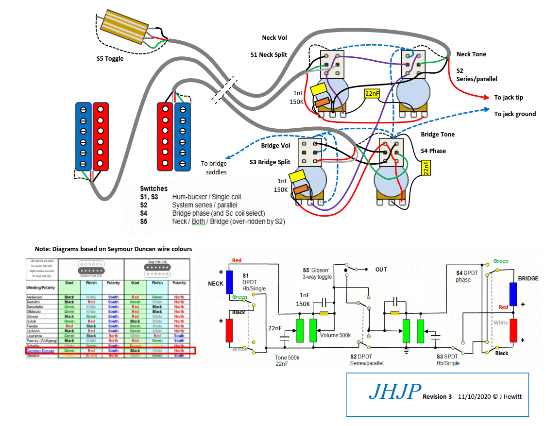
Ive been meaning to do this for at least 10 years. It's to update the wiring on this LP Jimmy Page version that I posted in 2007 so it aligns with the classic positions of LP controls and the most common placement of the switches for JP wiring:  The schematic is essentially unchanged from the original passive version of this scheme, with SD colours and also an update to treble bleed components based on later studies. I've also tried to capture the real orientations of pickups, polarities, poles and wires, so hopefully it would be easy to configure in practice. Push-pull pots usually have a handy solder lug to the case, at the top of the switch, so that's where all grounds get connected. The wires from the control cavity up to the main switch should be shielded, as they are in classic LP wiring. I show it here as a multicore screened cable, but it could also be divided into two or three separate cords. This new drawing is mostly a do-over and hasn't been built from yet, so it may need a check, but the schematic should be OK. JH |
|
|
|
Post by frets on Oct 11, 2020 23:27:20 GMT -5
John,
The wire crosswalk is the icing on the cake 🧁
|
|
|
|
Post by neophytebuilder on Oct 14, 2020 14:12:21 GMT -5
You're a star JohnH Thank you |
|
maxk
Rookie Solder Flinger

Posts: 11
Likes: 0
|
Post by maxk on Nov 15, 2020 0:22:33 GMT -5
JohnH , in preparation for my next wiring job, I've been lurking around this thread and staring at your schematic for way longer than i would like to admit. I'm happy to see you've returned with an updated diagram. Does this make "Mk1 passive output" diagram obsolete? I'm seeing alot more differences than just pot orientation. To add to the challenge, I want to do this scheme with reverse taper (lefty) pots. Will i be in serious trouble if i merely take your plan and mirror the lug wiring?
|
|
|
|
Post by JohnH on Nov 15, 2020 4:07:20 GMT -5
JohnH , in preparation for my next wiring job, I've been lurking around this thread and staring at your schematic for way longer than i would like to admit. I'm happy to see you've returned with an updated diagram. Does this make "Mk1 passive output" diagram obsolete? I'm seeing alot more differences than just pot orientation. To add to the challenge, I want to do this scheme with reverse taper (lefty) pots. Will i be in serious trouble if i merely take your plan and mirror the lug wiring? Hi maxk, thanks for your interest. I thought through the wiring again to suit the layout, so the old version can probably be filed away. I think, for a lefty, you could print out a left-right mirror image, which would give you a reference with the pots in the correct lefty places and the lugs adjusted too? The pots will all want to be reverse log taper ie type 'C' instead of 'A'. Can yoh get those as a long-shaft push pull? |
|
maxk
Rookie Solder Flinger

Posts: 11
Likes: 0
|
Post by maxk on Nov 15, 2020 12:46:23 GMT -5
Yes JohnH . The good people at RS Guitarworks custom make by hand 500K "reverse taper" CTS long shaft push pulls, even short shaft if requested. So with these push pulls i thought initially that only the input/output lugs need to be reversed. Are you saying that the wire placement on the 6 pins also need to be mirrored? |
|
|
|
Post by JohnH on Nov 15, 2020 14:01:31 GMT -5
The 6 lugs on each switch don't need to be flipped left-right, but its OK if they are. I just thought it might help to have a diagram where all the pots are where youll want them for a left handed layout, eg the neck volume is upper, nearest the neck
|
|
maxk
Rookie Solder Flinger

Posts: 11
Likes: 0
|
Post by maxk on Nov 15, 2020 14:23:10 GMT -5
Oh its not a problem, JohnH . I'll be taking your schematic into photoshop so i can do the pot mirroring and wire color converting to Dimarzio before i heat up any soldering iron. Thanks for clarifying everything! |
|
maxk
Rookie Solder Flinger

Posts: 11
Likes: 0
|
Post by maxk on Nov 16, 2020 18:31:42 GMT -5
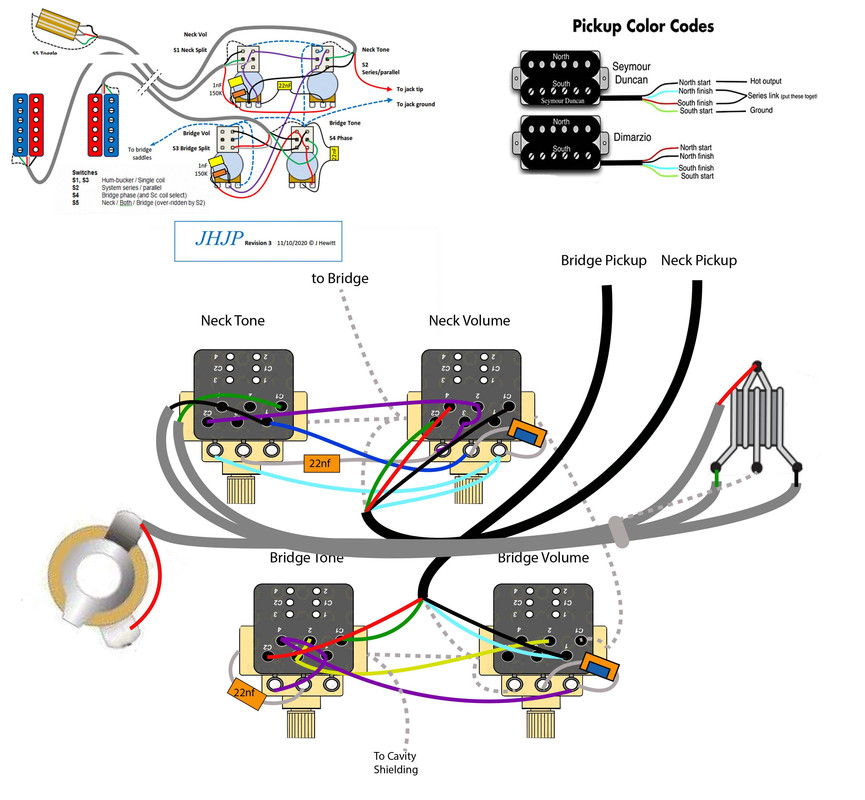
To JohnH and all my fellow solder soldiers. If you have some spare time, i could use another set of eyes to proofread my mock up for the lefty JHJP with reverse-tapered CTS push pulls and DiMarzio pups. The layout is in the view of the back of the guitar. Wires from the toggle switch will be the Gavitt braided cables which will be individually grounded. I would appreciate any critique, call outs for any undotted i's and uncrossed t's. Thank you.  |
|
|
|
Post by JohnH on Nov 17, 2020 6:15:09 GMT -5
Im having trouble relating your diagram to mine. The push/pulls look quite different, and I've seen what seems to be different wire connections. Can you not just do a left-right mirror of mine?
|
|
maxk
Rookie Solder Flinger

Posts: 11
Likes: 0
|
Post by maxk on Nov 17, 2020 14:07:51 GMT -5
It essentially is a left-right flip of your model. I just flipped the 3 lugs wiring but left your original 6 pin wiring unchanged. The CTS push pulls look different from the alpha/bourns model. However on each pot it shows the original 3 x 3 layout as a reference to the new inputs. Also to note, the wires are DiMarzio color layouts so maybe you are seeing more discrepancies.
|
|
|
|
Post by JohnH on Nov 17, 2020 15:02:24 GMT -5
These pots? - thanks I hadn't seen them before  On your diagram, Im seeing there's no purple wire from the bridge volume pot centre lug. The main toggle has center and top lugs reversed (unless you have a different switch). Also, the screened grey wires merge into one so are hard to check, maybe make them different shades? There may be other things since Im not used to looking at those switches. But Ill look again at the next version. |
|
maxk
Rookie Solder Flinger

Posts: 11
Likes: 0
|
Post by maxk on Nov 17, 2020 17:49:17 GMT -5
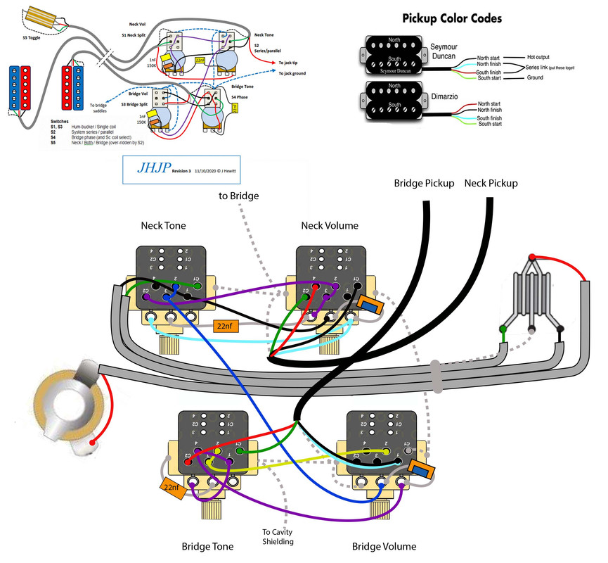
Okay. I slightly modified my schematic to address the missing jumper wire in the middle lug of the bridge volume, and improve overall legibility. My particular toggle switch has the ground and output to jack reversed so the picture reflects that.  |
|
|
|
Post by JohnH on Nov 18, 2020 14:40:14 GMT -5
Thanks Ill review it over the next couple of days. Do you have those pots in your hand now? I was wondering what you think of them in terms of general robustness, smoothness, switch feel etc. Are they based on a 16mm diameter pot?
|
|
maxk
Rookie Solder Flinger

Posts: 11
Likes: 0
|
Post by maxk on Nov 18, 2020 15:55:57 GMT -5
Yes i have it in hand. The pot is closer to 22mm in diameter. Its a quality pot and feels more rigid than bourns/alphas when turning the knobs, which many people prefer for precise dialing in. However, I think the bourns have a better, more graceful feel when using the push/pull feature. I like how smooth they click into place when pulling the knob out. The CTS pots, on the other hand, doesn't feel as great in my opinion.
|
|
|
|
Post by JohnH on Nov 18, 2020 16:10:41 GMT -5
Sounds like they are decent units.
It might also be worth checking with a meter, what lugs are connected when in normal pushed-in position. The usual push-pulls have the middle lugs connected to those furthest from the pot body in this position. Based on how these are labelled, Is that the same here?
Its worth a check, since switches can be constructed either way. eg with toggle switches, mostly if the lever is down, the connections are up, except for some that work the other way, but look the same.
|
|
maxk
Rookie Solder Flinger

Posts: 11
Likes: 0
|
Post by maxk on Nov 19, 2020 22:33:20 GMT -5
|
|
|
|
Post by JohnH on Nov 22, 2020 1:37:52 GMT -5
a couple more pick ups:
grounding of neck tone lug 4
main ground wire to jack
That's all I can spot though, good luck!
J
|
|
maxk
Rookie Solder Flinger

Posts: 11
Likes: 0
|
Post by maxk on Nov 22, 2020 22:10:22 GMT -5
Great catches. Thank you so much for your time and wisdom!
|
|
maxk
Rookie Solder Flinger

Posts: 11
Likes: 0
|
Post by maxk on Nov 25, 2020 22:11:52 GMT -5
Hey JohnH, Im about halfway soldering this spaghetti and praying i didnt fry anything but im curious what would you recommend I do about the unused lug in the bridge tone and neck tone pots? should i cut them off? |
|
|
|
Post by JohnH on Nov 25, 2020 22:44:04 GMT -5
usually you can just leave them as they are, assuming they aren't in the way of anything
|
|
maxk
Rookie Solder Flinger

Posts: 11
Likes: 0
|
Post by maxk on Nov 25, 2020 23:07:06 GMT -5
OK good to know. One more question. I shielded the cavity with copper tape. Would i run into issues if any leads i grounded by soldering to the side of the pot comes into contact with the shielded walls? should i cover the solder connection with electric tape to be safe?
|
|
|
|
Post by JohnH on Nov 26, 2020 1:30:31 GMT -5
I wouldn't think there'd be any issue if a grounded wire touches another ground.
|
|
JD
Apprentice Shielder
 
Posts: 29
Likes: 2
|
Post by JD on Feb 13, 2021 16:07:42 GMT -5
So, recently I have bought myself a couple of new guitars and I figured I could start experementing on my good old trusty Epi LP which 20+ years old pots are now basically on/off switches anyway. I Then started digging into possible upgrades for LP type wirings whitch led me to Jimmy Page's wiring and eventually, after a tons of wiring diagrams, I stumble upon John's design. I found it very clear (maybe because it was the only one I found with a circuit diagram which, from an engineering standpoint, is far easier for me to understand) and, according to comments here, had lots of qualities. I should mention at that point that this is my first step in the world of guitar circuitry so I had a lot to learn and understand before starting this project, and still do, hence my reason posting here. So I wanted to tackle a JP wiring with a few minor modifications. First of all, I am going for a P90 neck and HB bridge configuration. I will point out now that the P90 has been modded to have a 2 wires and 1 shield connections. I also wanted to add a treble bleed module on both pups. At that point, I started adapting John'sdesign to fit the P90 and I realized I was going to end up with a free DPDT switch. Re-reading this thread, there was a mention on local/parallel configurations on a HB. So obviously I had to add that on that free switch. You know, why make it simple when you can make it even more complicated... So here I am with this circuit diagram. I would love to have some comments or corrections ! I have moved around some of the push pull functionalities, like OOP is now on the neck volume (P90) which freed the bridge tone (HB) for the local serie/parallel switching. I'm not completely confortable with hum cancelling configurations (so far all I've got is south parallel to north) and pups polarity, and, as I mentioned before, this is my first attempt at modding a guitar wiring. So to sum up: LP Type Jimmy Page Wiring Based on JohnH’s design 2 Pick Ups: Neck P90 (2 wires + Shield) + Bridge HB (4 wires + Shield) 4 Push Pull Pots A 500K - Neck Volume : Out of Phase - Neck Tone : Global Parallel / Serie - Bridge Volume : HB Coil Split - Bridge Tone : Local HB Parallel Serie Please let me know what I've done right or wrong with these mods and thanks to John for his original design ! |
|
|
|
Post by JohnH on Feb 13, 2021 21:33:43 GMT -5
Hi JD, welcome to GN2 and thanks for your interest in this, and the nice diagram.
it looks basically fine to me, and a good candidate for the build. But there's one opportunity missed in the translation, and its not too important, but you might like to see if you can figure it out:
In the full HH version, humcancelling is maintained as well as possible when single coils are combined. So when you do coil cuts, and combine the two pickups, you'll get a north and a south coil, which is humcancelling in phase. When you reverse phase and do both coil cuts, you get two coils of the same polarity out of phase, which is also humcancelling.
So the puzzle for yours is, if you move the phase switch to the bridge and do it like on mine, can you deliver the north coil in phase and the south coil out of phase, so it humcancells with your neck P90 both ways, and also do the local series and parallel connections?
If not, proceed, it'll still be good!
|
|
JD
Apprentice Shielder
 
Posts: 29
Likes: 2
|
Post by JD on Feb 14, 2021 0:28:47 GMT -5
Thanks for your quick feedback!
Challenge accept... Wait, let's not get ahead of ourselves just yet.
I knew there were some details about hum cancelling that I was missing, so thanks for the explanation!
I had moved the OOP on the neck P90 for lisibility but in doing so I removed the subtility of your circuit of changing coils while going OOP...
I am going to try to put it back on the HB which may give something harder to read but it might very well be possible with the local parallel/série capability.
Just a quick question about hum cancelling whith 3 pups (either SC + HB or split HB + Full HB): the HB in itself is by definition hum cancelling, the SC is hum cancelling with one of the coils of the HB but not with the other or am I getting something wrong?
Anyway, I'm going to scratch my head on your puzzle and I'll post a new diagram if I get to something that seems right.
|
|
|
|
Post by JohnH on Feb 14, 2021 1:29:08 GMT -5
That all sounds right. And humcancelling is a bit moot with your set up anyway. But a P90 neck and a bridge HB would be a great combo.
The P90 will hum, as part of it being generally bad-a$$! The HB won't hum, and the simple combo of both will have a bit of hum.
Singles cut from the HB mixed with the P90, should have reduced him but probably not zero since they are very different coils.
But if you can solve the puzzle, there's no down-sides, so might as well.
|
|