JD
Apprentice Shielder
 
Posts: 29
Likes: 2
|
Post by JD on Feb 15, 2021 23:04:05 GMT -5
All right, I may have something, with some weird configurations...
1st of all, now that I know a bit more about humbucking, your design is even more clever than I thought!
So I've scratched my head quite a bit, and a lot of rejected designs later, I've ended up with 3 versions for the local parallel/serie configuration with HB split:
1) in phase it shorts the HB (with global parallel it shorts everything and in global serie I only have the P90 neck) and OOP the split is cancelled
2) in phase it shorts the HB (same as before) and OOP I have a single coil (Humbucking with the neck)
3) in phase it opens the circuit (global parallel gives Neck only and global serie circuit is open) and OOP single coil, still humbucking but with the other coil hanging from hot.
I'm tempted by the 1st one, and not sure the 3rd one's "hanging from hot" is advisable...
I'll try to make a circuit diagram by tomorrow.
I don't want to think about the mess of the wiring diagram just yet...
|
|
JD
Apprentice Shielder
 
Posts: 29
Likes: 2
|
Post by JD on Feb 16, 2021 17:02:44 GMT -5
And Here's The diagram !
I went with the 1st version (in phase it shorts the HB (with global parallel it shorts everything and in global serie I only have the P90 neck) and OOP the split is cancelled).
Ideally i would have made it so that when splitting the HB nothing would have happened at all while in local parallel, and that's the closest I could get for now, even though I still have the second half of the BV switch, I couldn't figure out where to put it...
Next step: wiring diagram ?
 |
|
|
|
Post by JohnH on Feb 18, 2021 16:08:00 GMT -5
I had a look at the diagram.
There's one issue that could be fixed if you wish:
When the bridge is in parallel mode, and you activate the single coil switch, it shorts out both coils giving no sound. If fully mixed in parallel with the neck, it shorts that out too.
All that doesn't detract from achieving all the sounds, its just that certain redundant switch positions cut the signal, which can be an annoyance if you didn't want it to happen.
Given there's a spare pole on the single-coil switch, it should be possible to improve on that, maybe just to deactivate the single coil function when in parallel mode.
A stretch target is; can we do all that and also avoid shunting the coils? Ill try some sketches too.
|
|
JD
Apprentice Shielder
 
Posts: 29
Likes: 2
|
Post by JD on Feb 18, 2021 16:28:22 GMT -5
Given there's a spare pole on the single-coil switch, it should be possible to improve on that, maybe just to deactivate the single coil function when in parallel mode. Yes that is exactly what I couldn't figure out. Not that I'm giving up just yet, but that's what I've got so far. Out of 24 configurations that gives me 8 redundancies and 2 switched off mode, so 16 configurations in total. I can't reach the 21 of a classic JP wiring with a single coil anyway. |
|
|
|
Post by JohnH on Feb 19, 2021 2:58:39 GMT -5
I have a schematic sketch It fixes the dead spots and also stops the coil shunting. There's just a minor issue with out of phase, single coil bridge, if the bridge series/parallel switch is set to parallel. you get one humming combo with neck. But the same if you set to bridge series is humcancellimg. so not compromising any needed setting. You can also get either bridge coil as a single on its own.
Ill post tomorrow.
|
|
JD
Apprentice Shielder
 
Posts: 29
Likes: 2
|
Post by JD on Feb 19, 2021 15:06:46 GMT -5
I may have circled around that kind configuration but chose the one that was giving me either no change or shunting the bridge when coil splitting since the no change at all was my goal. I only got half way ^^
|
|
|
|
Post by JohnH on Feb 19, 2021 22:44:55 GMT -5
Here's what I was thinking, drawn as a full module for the bridge circuit: (EDIT this one has problems! see below)  |
|
JD
Apprentice Shielder
 
Posts: 29
Likes: 2
|
Post by JD on Feb 20, 2021 0:57:50 GMT -5
Thanks!
I'll take a look after some sleep, at the moment I see one thing then another, so better start with fresh eyes...
|
|
|
|
Post by JohnH on Feb 20, 2021 1:10:07 GMT -5
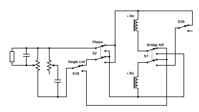
I think its all OK. This is a drawing app Ive recently started using. So joins are all dots, crossings are wires that cross without dots, no connection. S3A and S3B are parts of the same switch, but they do different things and aren't connected. S3A grounds the series-mode centre connection, so only the coil on the hot side works, and that changes when you pull the phase switch so you have access to each bridge coil S3B works only in parallel mode, cutting one coil.
I wish there was a free App that drew not only the connecting dots but also the crossing loops that we were taught in school.
|
|
JD
Apprentice Shielder
 
Posts: 29
Likes: 2
|
Post by JD on Feb 20, 2021 1:12:43 GMT -5
Sorry I edited my post while you were replying,
And as I was saying I realized I was wrong tight after I posted so tomorrow I'll get right back on that ^^
|
|
JD
Apprentice Shielder
 
Posts: 29
Likes: 2
|
Post by JD on Feb 20, 2021 11:07:59 GMT -5
I am still confused about the split + local parallel mode..
S3A and S1 are on the down position 1nd I don't see how the ground (minus) wire connects to either coils of the humbucker
|
|
|
|
Post by JohnH on Feb 20, 2021 14:03:14 GMT -5
Thanks yes you are right! Ill try some more....
|
|
|
|
Post by JohnH on Feb 20, 2021 16:11:54 GMT -5
Im glad you checked, seems it cant do all i was trying for. So here's a proposal  The blue wire should hopefully preserve some grounding for parallel mode if you engage single coil. But now single coil mode is done by shunting. Its actually OK, and very common, but not shunting is better. But it offers a new opportunity, to do a partly shunted version via a cap, which is in red. Bridge humbuckers cut to singles are sometimes very thin sounding, so tis preserves some bass from the bypassed coil. I have it on my own LP instead of full bypass. So now there are three single sounds just from bridge, being two with one coil cap-bypassed and also a pure non-bypassed single available in parallel mode with coil-cut Better check it though, I could be out to lunch still! |
|
JD
Apprentice Shielder
 
Posts: 29
Likes: 2
|
Post by JD on Feb 20, 2021 17:54:37 GMT -5
Interresting! I didn't know split could be done like that. It looks like a LC type low pass filter on the first coil into the second coil. Only active in local serie HB mode.
in local parallel in phase it's a classic single coil, but if I got it right, in OOP the single coils configuragion is not hum cancelling (P90 South with HBSC North OOP) and the South coil is hanging from hot.
|
|
|
|
Post by JohnH on Feb 20, 2021 18:15:44 GMT -5
yes i agree with all that.
The cap bypass sound is an interesting one, and you can try different caps 10 to 100nF. The bigger the cap, the more its like a full coil cut. It keeps the treble edge of the main coil, while adding that bit of added weight.
If you try something like this, it needn't be the end of the story since an LP is easy to get access to and rewire.
|
|
JD
Apprentice Shielder
 
Posts: 29
Likes: 2
|
Post by JD on Feb 21, 2021 0:44:32 GMT -5
Well if shunting a coil (with or without cap) is an option, there are more design opportunities . With a quick mod to my last circuit I think I may have something.
In local parallel mode, splitting the coil would give either a complete shunt or a coil and a cap in parallel... At least phase and out of phase, would be consistent.
I'll sleep on it and come back with a circuit ASAP.
|
|
JD
Apprentice Shielder
 
Posts: 29
Likes: 2
|
Post by JD on Feb 21, 2021 18:35:23 GMT -5
So I was messing about with your coil tapping idea with a shunt/Cap in my design and I think I've reached something with a new configuration. Diagram: So, in Local Parallel and coil split I have, in phase, a single coil Hum-cancelling with the neck single coil or OOP, the part on the right of the diagram below. I've read that a cap in line with a pickup is high pass filter this time. So the bridge HB in this config would sound very trebly but It's a LP we're talking about, how bad can it be....
But I'm not sure how it will react with the Neck engaged either in series or in parallel (see diagram below for config)
All that work for a local parallel config ^^
|
|
|
|
Post by JohnH on Feb 22, 2021 7:34:39 GMT -5
Looks like that will do as described.
I've never really investigated nor tested that parallel with cap setting. You may find that the ideal cap for it is a different value to the ideal one for the series bypass cap, which I do know well.
So I wonder if the cap for series can be in a different place to thst for parallel, so it can be a different value ?
|
|
JD
Apprentice Shielder
 
Posts: 29
Likes: 2
|
Post by JD on Feb 22, 2021 19:49:39 GMT -5
|
|
|
|
Post by JohnH on Feb 22, 2021 20:25:29 GMT -5
Sure! you'll have to try it, it's easy to change.
|
|
JD
Apprentice Shielder
 
Posts: 29
Likes: 2
|
Post by JD on Feb 23, 2021 11:53:46 GMT -5
Any opinion on the resistor inline with the cap to shunt the unwanted coil ?
|
|
|
|
Post by JohnH on Feb 23, 2021 16:33:59 GMT -5
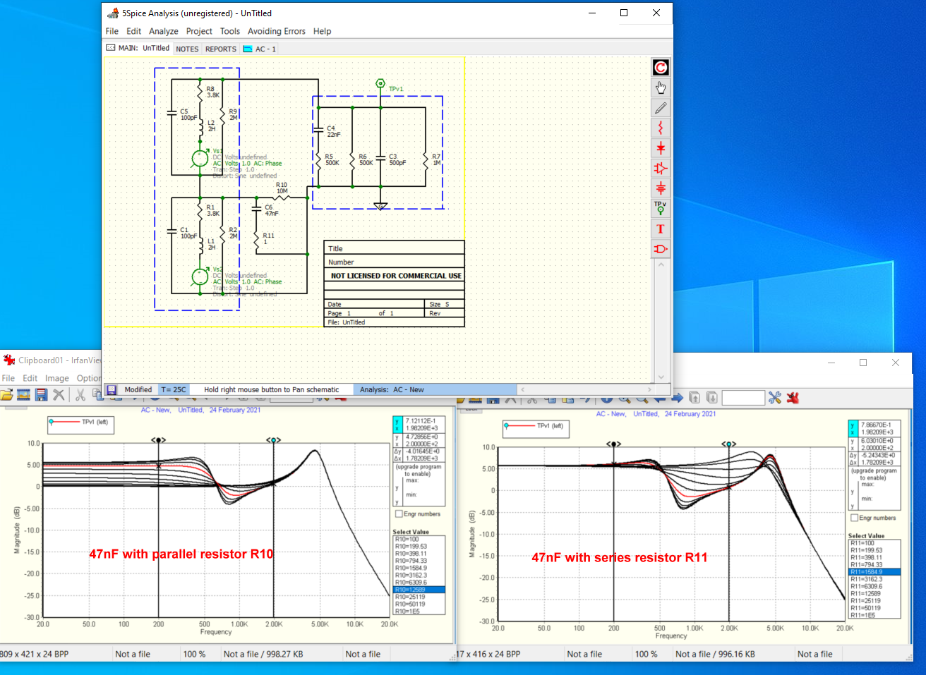
Any opinion on the resistor inline with the cap to shunt the unwanted coil ? When i was testing my own LP (with PAF type humbuckers), I liked the bypass sound with just a 47nF and no resistor best, and i liked a pure coil cut on my neck pu. I tried a few resistor variations. But heres something to look at:  Its an approximate Spice model of a SD59 pickup, split in two, connected to volume and tone circuits, and then via a cord to an amp. I have the two coils with one bypassed by a cap with either a series resistor or a parallel resistor. The two plots show sweeping the values of one of the resistors with the other made negligible (ie to negate one, a very small series resistor or very large for parallel). The full humbucker tone is represented on the right by the top line, ie, a very large series resistor, effectively negating the cap. And you can see how the cap can scoop the mids and extend the treble peak on both graphs. You can see the complete fully bypassed single tone on the left, with a basic flat response along the bottom, rising up to the high peak Apart from more bass, and a higher frequency peak, all the interesting action is around the mids. Either resistor scheme somewhat smoothes this zone. To do this but not affect high and lows too much, it looks like around 1.5k to 2.5k in series, or, 10k to 20k in parallel might be good. The red lines are at about 1.5k and 12k respectively. Change the cap and the midrange 'wiggle' will move to higher or lower frequency. (halve the cap, wiggle will raise to frequency x 1.4) But you can't really tell how things will sound, or whether youll like them, by looking at charts. So its best to set up so that you can test a few variations. That should be easy enough o do and if you try it, it will be intersting to see what you think. Also, it was interesting to see how in your blog link above, he also used 47nF, which is where I got to just by listening. Its interesting anyway. If you want to do runs like this yourself, there are various SPICE programs freely available. This one is 5Spice, but its discontinued. Most people use LTSpice which is very powerful but a bit more clunky to use. |
|
JD
Apprentice Shielder
 
Posts: 29
Likes: 2
|
Post by JD on Feb 23, 2021 17:17:01 GMT -5
Man I was hoping I could never have to use spice ever again!
Probably some PTSD from my studying years... I quickly moved to digital electronics rather than analog ^^
Anyway I was thinking along the same line about wiring the thing with connectors for the shunt module.
I've already wired the pups like that on the old controls so I might as well use the same connectors for that module and prepare a few to test.
So wiring diagram now and then... It's going to be hell to solder all that in tiny spots... I was never going to be a surgeon...
|
|
JD
Apprentice Shielder
 
Posts: 29
Likes: 2
|
Post by JD on Feb 25, 2021 15:13:50 GMT -5
And here's The Config Table ! There are 19 distinct configurations out of 25 possible.
Legend:
0: Push Pull down (default)
1: Push Pull Up (active)
N: Neck B: Bridge Bsc: Bridge Single coil Hum Cancelling B//: Bridge in parallel mode B//*: Special config mentionend in a post above
-X: Pickup out of phase (only effective in either series or parallel mode with Neck) X+Y: pickup X and Y in parallel (Normal Setting) X -> Y: X and Y in line (Series mode)
PS: I've started working on the wiring, it's going to take some time... ^^'
|
|
|
|
Post by airistubolis on Feb 25, 2021 18:28:27 GMT -5
 A blank canvas for ya. lol |
|
|
|
Post by airistubolis on Feb 25, 2021 19:28:04 GMT -5
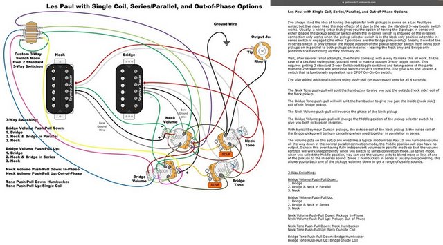
How does the JHJP compare to this? other than modified switch and no treble bleeds.  |
|
|
|
Post by JohnH on Feb 25, 2021 20:13:10 GMT -5
Hi aristubolis, welcome to GN2
Can you please post a link to that wiring diagram? its not coming through clearly to me, I cant read the wording
|
|
|
|
Post by airistubolis on Feb 25, 2021 20:16:58 GMT -5
|
|
|
|
Post by JohnH on Feb 25, 2021 21:04:51 GMT -5
Ah thats one of Phostenix' designs. It will be very good. Main differences are:
He makes a special 3 way switch of out parts from two, so he can have B and N with series just in the middle. My one goes all to series disabling the toggle in series mode, using a normal toggle. Also, in series mode, mine lets you mix the contributions from each pickup, whereas I think his does not.
Im not sure if he's taken all humcancelling optimisations and avoiding coil shunting as I have.
|
|
JD
Apprentice Shielder
 
Posts: 29
Likes: 2
|
Post by JD on Feb 26, 2021 14:54:59 GMT -5
And you can't even build it from the closed switch that you find sometimes, in my Epiphone for instance...
Any advice on how to render the wiring on a computer ? I have it drawn by hand on paper but how to make beautiful twisted wire ? photoshop ? vector graphic software ?
once I have everything, should I start a new thread ? or post everything here as final design ?
|
|