|
|
Post by ChrisK on Dec 3, 2008 19:15:07 GMT -5
Wiring diagrams are great if one wants to see how it's implemented (external view/plumbing/instantiation). For simple things these are fine.
Schematics are required to "see" the logic flow and theory behind the design, and to see how it can be transposed(concept).
I speak schematic, wiring diagrams are just local dialects.
In this case, enough theory was dispensed (sans schematics) such that all "saw" the solution.
|
|
|
|
Post by angelodp on Dec 3, 2008 19:45:05 GMT -5
Well ok then seems like it has the seal of approval. Another thanks to all and I will report back when the guitar is closer to playing status.
BTW Instantiation ... great word.
best Ange
|
|
|
|
Post by angelodp on Dec 3, 2008 23:01:17 GMT -5
Sorry to dither a bit but i thought I would try out a plan that uses the GuitarNuts method for grounding and DC cap .... what do you think... still kosher?? best Ange 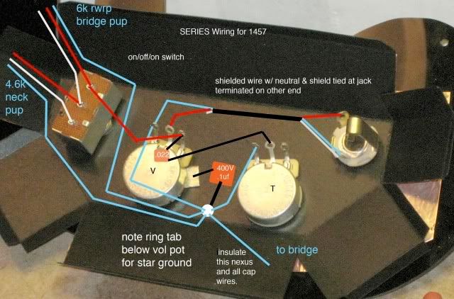 |
|
|
|
Post by pete12345 on Dec 4, 2008 3:35:18 GMT -5
By all means use the isolation capacitor- how you have it will be fine. The shielded wire between the volume and jack isn't necessary though- it's contained within the faraday cage box. It's only needed on strats etc where the output jack is away from the main cavity. It won't hurt to use it of course, but regular wire would be fine here, as with everywhere else.
|
|
|
|
Post by angelodp on Dec 4, 2008 3:44:44 GMT -5
Can you explain how the signal travels from the 4.6 pickup to the jack... for the life of me I cannot understand that path. I wish someone would do a diagram of the signal path a typical three pickup strat or les paul.
thanks A
|
|
|
|
Post by ChrisK on Dec 4, 2008 12:42:14 GMT -5
|
|
|
|
Post by ChrisK on Dec 4, 2008 12:58:26 GMT -5
Yeah, we use them there neat words in the modern software/embedded world. You know, like taxonomy, coercion, enumeration, heterogeneous, framework, use case, encapsulation (a specific instantiation of a thing or group of things, sometimes in an actual real thing).  Then there are words like homomorphic, which is a real word and related to mathematics theory (i.e. the four color theorem), but try explaining that to the company VPN IT Nazi's when you get caught trying to surf a web site while doing research on homomorphic behaviours. ;D   |
|
|
|
Post by angelodp on Dec 4, 2008 13:35:24 GMT -5
Ok, that helped, I wish I could have seen that myself. Being a visual person I can make sense of things when i see it, but I just don't get electronics at times. What i was asking for was not just a diagram of the circuit but a graphic for the flow in that circuit. Just a few arrows that show the path of electrons if you will. Anyhooow thanks for getting me on path here. That extra wire is now shown and it does make more sense to me. 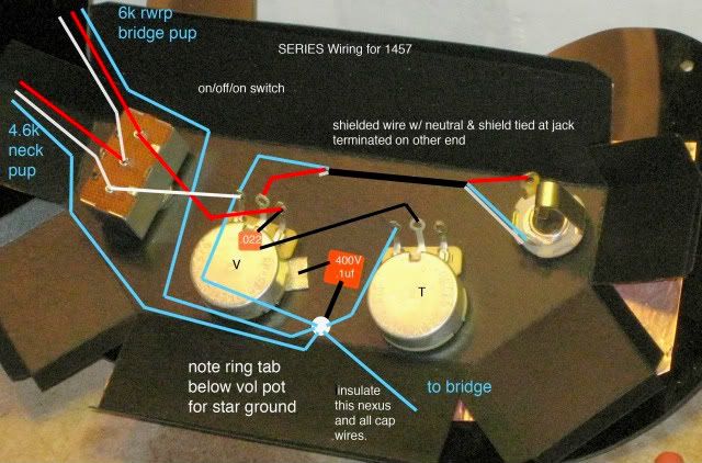 |
|
|
|
Post by newey on Dec 4, 2008 13:55:47 GMT -5
Since guitar circuits are AC, it would simply be a two-headed arrow pointing in both directions, since the "flow", if you will, reverses direction several times per second (with the rate varying with string vibration).
|
|
|
|
Post by ashcatlt on Dec 4, 2008 15:28:47 GMT -5
While newey is technically correct, I think we all know what you're talking about. I find it helpful sometimes to try and trace through the wires like a maze. I usually start at ground and see if I can find a path through to the hot output. This particular wiring is deceptively simple. That is, there isn't much going on, but it's a bit counterintuitive. We'll ignore the pots, they really are just tacked on at the end. Follow the blue lines...  Does that help? |
|
|
|
Post by angelodp on Dec 4, 2008 16:37:49 GMT -5
Ok, its wired and tested and works. Whew!! I will install in the 1457 once its finished up. Have some painting to do, make an aluminum nut, dress some frets, etc. and I am almost there. Once again thanks to this marvelous community and your patience and experience. Cheers Ange 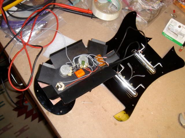 |
|
|
|
Post by ChrisK on Dec 4, 2008 19:09:06 GMT -5
|
|
|
|
Post by angelodp on Dec 5, 2008 4:03:52 GMT -5
very helpful.... thanks
|
|
|
|
Post by angelodp on Jan 18, 2009 23:20:50 GMT -5
Something weird with this wiring I think. These pups are much higher impedance than the vintage pups and they sound very thin in the position that selects either pickup. In the middle position of the switch I do get a nice strong tone from the series signal. I am wondering if I have a problem with this wiring set-up. Its wired just as the last diagram shows. Any help trouble shooting is appreciated. This took a while as I initially tested the rig to see if it worked while I finished the neck but never really did a tone test.
|
|
|
|
Post by ChrisK on Jan 19, 2009 1:54:17 GMT -5
Is this how it's wired?  If so, I think that there are some isolation safety issues. The bridge and pickup cases are connected to the output jack (and hence amp) ground. The 0.1 uF 400 VDC (?0.33 uF 400 VDC?) cap only isolates the volume pot shell from the ground nexus. If the Faraday cage is conductive, nothing is isolated from anything and the cap is just excess baggage.  |
|
|
|
Post by angelodp on Jan 19, 2009 16:16:22 GMT -5
Yes this exactly how its wired. The faraday cage is conductive there is continuity through the hex nuts at the switch, volume and tone as well as the jack. Is this causing the sound problems?? What do you recommend?
A
|
|
|
|
Post by ashcatlt on Jan 20, 2009 0:02:20 GMT -5
What ChrisK is talking about there probably won't cause the issues you mentioned with the sound.
It's more that you've defeated the point of the isolation cap, at least where the pickup covers are concerned. You've attempted to create the star ground topology described in QTB, but misinterpretted. The "nexus" which should be insulated from the shielding should collect all signal return points. All "shield" connections - including pot shells, etc - should be on the other side of the cap.
The pickups in the QTB instructions do not seem to have the 3rd, seperate shield wire that yours do, so they are not accounted for. Your scheme is as star grounded as it's going to get, collecting all signal returns at the left lug of the V pot.
For the issue you actually asked about, have you adjusted the height of the pickups themselves? This is always my first quesion because it's the simplest to remedy, and so trivial that it's often overlooked.
|
|
|
|
Post by angelodp on Jan 20, 2009 17:24:58 GMT -5
Ok I did adjust the heights and that helped. I will post a diagram for the re-wire regarding the nexus issue.
Thanks A
|
|
|
|
Post by ChrisK on Jan 20, 2009 21:01:39 GMT -5
In essence, the ground connection from the amp (the cord shield) is capacitor isolated from anything "touchable" by humans.
On the amp ground side of the cap one would connect the signal returns from the pots, pickups, and any circuit signal return point.
On the other side of the cap one would connect the pickup cases (any touchable metal cover), the pot shells (especially if metal knobs are used), the bridge/string ground, any exposed metal plates, and essentially any humanly touchable, electrically conductive things.
|
|
|
|
Post by angelodp on Jan 21, 2009 17:36:52 GMT -5
|
|
|
|
Post by ashcatlt on Jan 21, 2009 23:09:41 GMT -5
Again, those pickups don't have the third shield wire to deal with. The wires you see collected at that star ground are signal return wires. Your pickups' signal return wires are collected at the switch.
|
|
|
|
Post by angelodp on Jan 22, 2009 17:31:27 GMT -5
Could anyone suggest the proper wiring diagram then.
|
|
|
|
Post by ChrisK on Jan 22, 2009 20:57:49 GMT -5
The link that you posted is correct. i260.photobucket.com/albums/ii9/angelodp1/1457comp.jpg?t=1232577299Your wiring does not match it. The ground connection from the amp (the cord shield) is capacitor isolated from anything "touchable" by humans. On the amp ground side of the cap one would connect the signal returns from the pots, pickups, and any circuit signal return point. This is the "north/top" end of the cap in the link. It's labeled "signal return". On the other human touchable side of the cap one would connect the pickup cases (any touchable metal cover), the pot shells (especially if metal knobs are used), the bridge/string ground, any exposed metal plates, and essentially any humanly touchable, electrically conductive things. This includes any internal shielding that might touch any of these things. This is the "south/bottom" end of the cap in the link. It's labeled "to ring terminal on pot mounting shaft". For the isolation cap to be isolating, the jack/amp ground must not be in contact with any point in this group. |
|
|
|
Post by angelodp on Jan 23, 2009 1:11:08 GMT -5
Chris, I am not getting my brain around this.... any chance you can pencil this out on the blank slate.... forever thankful ange 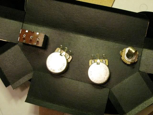 |
|
|
|
Post by ChrisK on Jan 23, 2009 21:04:00 GMT -5
If I were to draw it, you would not learn the rational behind this, and likely might implement such isolation circuitry in other instruments to no avail or safety.
It will also take about 1 hour.
I've exactly explained this.
Your statement before of:
indicates that the jack sleeve (the hex nut and hence the amp ground connection) has electrical continuity to the Faraday cage shield which also has electrical continuity with the 3-way switch housing, pot shells, bushings, shafts, knobs (if metal), the metal pickup covers, and the bridge/strings, thus completely defeating the isolation cap.
You also have several of these points hardwired together.
THIS IMPLEMENTATION PROVIDES NO SAFETY ISOLATION.
The isolation cap is pointless here.
The guitarnuts drawing is correct. You need to make yours match it electrically. You must not connect the Faraday cage to the output jack sleeve bushing if it is in contact with any of the electrically conductive, humanly touchable parts of the guitar.
For the output jack sleeve/bushing, you must make a cutout in the Faraday cage approximately 20mm in diameter concentric with the bushing hole thru the body, ensuring that the jack HAS NO CONNECTIVITY TO THE CAGE.
You must connect the two disparate circuit sections as I have indicated, to match the guitarnuts drawing.
procedure
1. Make a cutout in the Faraday cage approximately 20mm in diameter concentric with the bushing hole thru the body.
THE AMPLIFIER CIRCUIT GROUND NEXUS
2. Connect all of the pickup wires, pots, tone cap and output jack wires as you had them before, BUT DO NOT CONNECT ANY POT SHELL, THE FRAME TERMINAL ON THE 3-WAY SWITCH, THE BRIDGE/STRING GROUND WIRE, THE METAL PICKUP COVER WIRES, OR ANY EXPOSED, HUMANLY-TOUCHABLE CONDUCTIVE OBJECTS TO ANY POINT IN THIS CIRCUIT NODE.
The nexus of this circuit node should be the volume pot "0" terminal (the left fully anti/counter-clockwise) one in your drawing).
This nexus amplifier ground terminal will have one wire from the 3-way switch,
a wire from the tone circuit,
the ground wire to the jack sleeve/bushing,
and one wire lead from the isolation cap.
THE ISOLATED GUITAR SAFETY GROUND NEXUS
3. Connect the points specifically directed to not connect to the above as follows:
Solder to the back shell of the volume pot a wire soldered to the back shell of the tone pot (do not depend on the Faraday cage to do this, it's a shield, not a conductor).
Solder to the back shell of the volume pot each shield wire from the pickup covers.
Solder to the back shell of the volume pot the bridge/string ground wire.
Solder to the back shell of the volume pot a wire from the frame terminal on the 3-way switch.
Solder to the back shell of the volume pot the other wire lead from the isolation cap.
/procedure
Done is.
If you draw it, you'll "see" it.
|
|
|
|
Post by angelodp on Jan 24, 2009 0:54:21 GMT -5
You are most kind and yes I will draw it out.
Thanks Ange
|
|
|
|
Post by angelodp on Jan 24, 2009 14:02:01 GMT -5
|
|
|
|
Post by ashcatlt on Jan 24, 2009 23:11:27 GMT -5
I had missed the fact that your jack was connected via the cage. What you've drawn looks much better to me, except that the wires connecting the switch and tone pot bodies to the volume pot are redundant with the faraday cage. This might be a ground loop, and should be avoided for "best practice" reasons.
|
|
|
|
Post by ChrisK on Jan 25, 2009 0:55:17 GMT -5
Since I don't know what material the Faraday cage is constructed of, I suggested the wire between the pot shells. Since these are both shielding points rather than signal points, ground loops will not be of concern.
Pretty darn good.
With the exception that you are missing a wire from the left terminal on the tone pot to the left terminal on the volume pot (the return from the tone circuit to the signal/amp ground).
I am concerned about what a "20 mm bushing" really means. Does it insulate along the threaded part of the output jack (the amp ground) that passes thru the cage as well as the surface against the Faraday cage?
This is why I suggested that a 20mm concentric hole (the diameter of the jack body) be cut in the shield to eliminate any possible contact with any part of the Faraday cage to the jack.
|
|
|
|
Post by angelodp on Jan 25, 2009 16:07:02 GMT -5
Ok added that tone wire. The Farady cage is made of cardboard and has copper foil on the outside which completely encases the innards. I will be sure that the threads on the output are not touching the copper in any way. The switch, and Volume and Tone pots are linked via the threads to the F-cage ( is that ok ?? ). So is this looking like a go yet. thanks A 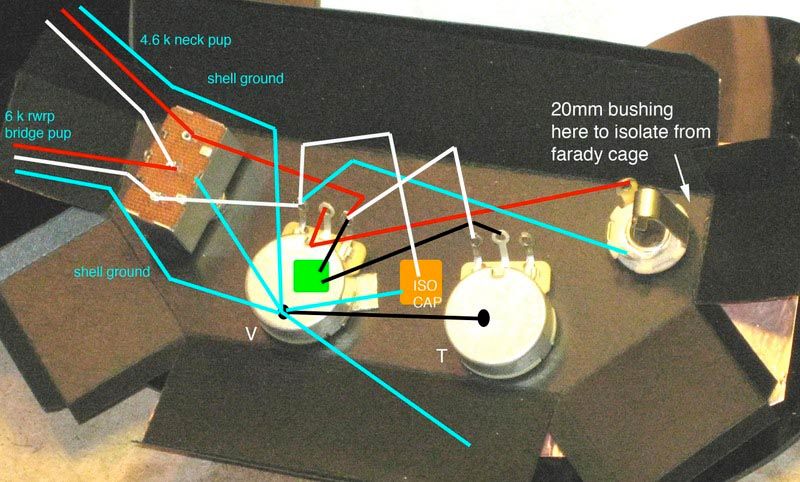 |
|