|
|
Post by angelodp on Jan 25, 2009 18:01:49 GMT -5
|
|
|
|
Post by ChrisK on Jan 26, 2009 0:05:03 GMT -5
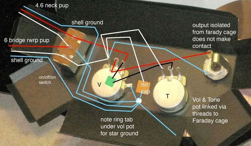
...from the left terminal on the tone pot to the left terminal on the volume pot..... You have it going to the right-side terminal on the volume pot (the output signal, it needs to go the the amp ground). Both leads to the tone circuit come from the same point to no effect. Thanks for explaining the structure of the Faraday cage. Sure, be sure to implement the following suggestions. The reason that I suggested the isolation hole around the output jack is to guarantee that there is no electrical contact to the copper foil layer. This isolation spacing should be at least 1/16" or 2mm. If you're using a 400 VDC cap, you should use a 400 VDC gap.  Since the copper foil is on the other side of the Faraday cage material from the pot shafts, and presuming that the hex nuts on said pots are on the other side of the body or pick guard, how can you guarantee that there is electrical contact from both pot shells, the bridge/string ground, and the switch frame to the copper foil layer, especially if the copper is between the black insulating layer of the cage and the wood or pick guard? You need to ensure that the pot shell structure is in electrical contact with the copper layer on the cage, or it will not be a Faraday cage, but just a floating copper shell. You need to wire the pot back shells together. You need to directly solder a wire from the cage copper layer to the volume back shell. |
|
|
|
Post by angelodp on Jan 26, 2009 8:47:29 GMT -5
...from the left terminal on the tone pot to the left terminal on the volume pot..... ok I will change that.... nutty mistake. Thanks for explaining the structure of the Faraday cage. If I am reading for continuity on the two pots and the switch and I do get electrical contact via the hex screws and threads pressing against the foil ( I put small pieces of copper foil in th holes bent over towards the inside for contact ) then I should be fine. There has to be contact between the pots, switch and faraday cage, but none at the output. Have i got it right? i260.photobucket.com/albums/ii9/angelodp1/1457rewire-6.jpg?t=1232977537The reason that I suggested the isolation hole around the output jack is to guarantee that there is no electrical contact to the copper foil layer. This isolation spacing should be at least 1/16" or 2mm. If you're using a 400 VDC cap, you should use a 400 VDC gap.  Since the copper foil is on the other side of the Faraday cage material from the pot shafts, and presuming that the hex nuts on said pots are on the other side of the body or pick guard, how can you guarantee that there is electrical contact from both pot shells, the bridge/string ground, and the switch frame to the copper foil layer, especially if the copper is between the black insulating layer of the cage and the wood or pick guard? You need to ensure that the pot shell structure is in electrical contact with the copper layer on the cage, or it will not be a Faraday cage, but just a floating copper shell. You need to wire the pot back shells together. You need to directly solder a wire from the cage copper layer to the volume back shell.[/quote] |
|
|
|
Post by ChrisK on Jan 26, 2009 13:23:07 GMT -5
Yes.
|
|
|
|
Post by angelodp on Jan 26, 2009 22:18:03 GMT -5
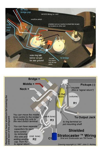
That nexus of four wires at the volume pot sure looks weird to me..... have I got it correct. I do not see anything like that at the GN site.  Ange |
|
|
|
Post by ChrisK on Jan 26, 2009 23:18:39 GMT -5
Yes. It's there, you just don't see it. The equivalent point is the north end of the isolation cap (the pickup (-) leads) on the GN drawing that you posted. Remember, your pickups are in series. We're doing it at the volume pot since its easier (and that terminal is part of the node anyway).  |
|
|
|
Post by angelodp on Jan 27, 2009 1:13:24 GMT -5
Chris, thanks loads for helping me out again. I will be implementing this shortly.
best A
|
|