|
|
Post by Runewalker on Jun 9, 2012 23:20:11 GMT -5
Very nice renderings both chaps. RW, 'tis a joy to see your artistry with Word-shapes again. On the last diag, if pickup colours relate to polarity, you should reverse the colours on either the bridge pup, or the N/M pups, to make it possible to find in-phase combos of inner and outer pairs. ..... so Retread, will you be adding the wiring to the diagram? If you wish to, please do! or I'll have a go if you prefer. John Thx for the nod John. Yes, I "forgot to remember" the pup color re-arrange. Thanks for the reminder. Fixed it on the diagram. I have the Word doc, or the PDF and jpg views if that is easier to work off of. Pmail me with an email I can send attachments to. To make it easy if one of you could even hand draw the wires on the components image, I could go back and put them on my Word doc. However I can help, let me know. I'll ask a little more about the buffer later. Thanks RT & JH! RW |
|
|
|
Post by reTrEaD on Jun 9, 2012 23:26:36 GMT -5
John I think when the time comes, you have better tools and skills to do the final drawing. But if we take it in stages, I can probably try a few things in the evolution of the pieces that might be helpful. Rune, I guess North-South isn't as good of a description as I had originally thought. When I think N-S, I consider North to be the headstock and South to be the bridge. But I guess north could be "up" when the guitar is in playing position. So are you saying you want the toggle to be oriented like this, only shifted to the lower horn?  |
|
|
|
Post by Runewalker on Jun 9, 2012 23:28:37 GMT -5
Fair enough, me too. as you can see on my tele, it is just a subtle twist. my LP and load strat is similar..but a small point. Great work on the diagrams... Thx 4R. I will try to make the switch hole large enough, and wiring slack enough, to allow me to experiment with N/S or E/W. My intuition is that switching btw guitars would be clunky if the orientations flipped around. The less I have to think about complexity while playing the better. That statement sounds a little conflicted given my penchant for way too many options. Thx RW |
|
|
|
Post by Runewalker on Jun 9, 2012 23:36:37 GMT -5
ReTread"John I think when the time comes, you have better tools and skills to do the final drawing. But if we take it in stages, I can probably try a few things in the evolution of the pieces that might be helpful." I will be happy to do the rendering if one of you will pencil up the image/pdf/word file and send or post the scan. Rune, I guess North-South isn't as good of a description as I had originally thought. When I think N-S, I consider North to be the headstock and South to be the bridge. But I guess north could be "up" when the guitar is in playing position.
So are you saying you want the toggle to be oriented like this, only shifted to the lower horn? Where's the North Star when you need it. Yes, exactly like a Les Paul. Note in the reply to 4Real I suggested also I will try to make the installation flipable to experiment with playing preferences. I just suspect that with all of the HHs I have with up/down toggles I prob better stick with that. Thx RW
|
|
|
|
Post by reTrEaD on Jun 9, 2012 23:47:14 GMT -5
Given the drawing skills both of you have, this thing has the potential to be something stellar. One concern I do have is the .jpg files. They tend to degrade with each generation. Probably better to use .png
|
|
|
|
Post by JohnH on Jun 10, 2012 2:17:29 GMT -5
Meanwhile, here's a sound clip. I was looking for a way to show the cap bypassed sound in relation to the others. The nearest I have is on my piezo-equiped Ibanez, using the N and M pups only: www.soundclick.com/bands/page_songInfo.cfm?bandID=674084&songID=11697775Its, Neck, Middle, N+M, NxM with neck bypased by a .047 cap, then NxM Despite what I said before, the cap bypassed sound is nearer to the full series than a single, in this case. Its not as dark as the full series though. But on the LP, I use this configuration in place of a single coil cut. Here's a clip of that: www.soundclick.com/bands/page_songInfo.cfm?bandID=674084&songID=11697831It the Lp bridge pickup, with a full coil cut, cap bypassed Hb then full Hb (no local para on that one) Recording was through my Marshall combo, DI out, with cab sim. cheers John |
|
|
|
Post by Runewalker on Jun 10, 2012 7:12:53 GMT -5
Given the drawing skills both of you have, this thing has the potential to be something stellar. One concern I do have is the .jpg files. They tend to degrade with each generation. Probably better to use .png I am all over stellar. I'll have to look at the free drawing prog I have on the png conversion. Translating Word files to graphics has always been clunky. I print to pdf, then export that to jpg. So I will have to work on the alternative translation. Any other ideas on converting Word files to .png-s? |
|
|
|
Post by Runewalker on Jun 10, 2012 7:18:54 GMT -5
Despite what I said before, the cap bypassed sound is nearer to the full series than a single, in this case. Its not as dark as the full series though. But on the LP, I use this configuration in place of a single coil cut. Here's a clip of that: It the Lp bridge pickup, with a full coil cut, cap bypassed Hb then full Hb (no local para on that one). Recording was through my Marshall combo, DI out, with cab sim. cheers John Interesting that the Roadstar's views were more subtle than the LP. Diffs are clear on the LP. Thanks for the illustration. That helps. I don't know of another alternative sound approach with a Local switch, except Local OoP. When I have done one of those it was really more of a novelty tone, more of a throwaway to do just because I could. Perhaps the difference in the bypass cap view could be emphasized more with different cap values? Thx JH RW |
|
|
|
Post by JohnH on Jun 10, 2012 8:16:56 GMT -5
When I do diagrams, using Word, I just arrange a view of the right on-screen size, then ctrl-prnt screen, and paste from the clipboard into any graphics program - I use Irfanview. Then I crop the image and save as a giff file.
With the sound clips, the difference of the bypassed to full Hb is clear in practice. On both those guitars it is on a pot and there is a clear 'wah..' like transition between those tones. The bypass cap value is important though. the bigger the cap, the more it is nearer to a single coil.
J
|
|
|
|
Post by newey on Jun 10, 2012 8:30:48 GMT -5
Rune said: "Sounds like a job for 5spice", thought I, but it seems I'm too much of a noob with 5 spice to model this correctly. Here's what I did, but I'm not at all sure that putting the 2 AC voltage sources in series (with cap between) is a correct model of the real-world situation: 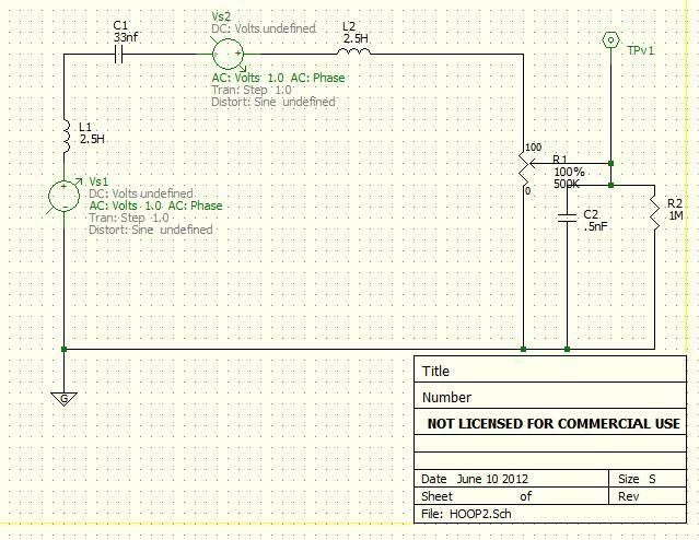 Here's what I get, sweeping the cap from 1nf to 100nf. As noted, however, I suspect that I haven't got this right. If, by some chance, it is right, there doesn't seem to be much difference . . . 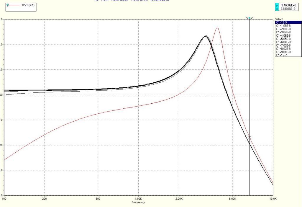 I suspect I'm trying to be too clever here. |
|
|
|
Post by JohnH on Jun 10, 2012 8:42:03 GMT -5
Newey - the cap c1 would be in parallel with one of the inductors,instead of in series with both
J
|
|
|
|
Post by newey on Jun 10, 2012 11:45:07 GMT -5
Aha! I'll try again when I get a chance. Thanks, I knew I was missing something.
|
|
|
|
Post by newey on Jun 10, 2012 16:54:39 GMT -5
Ok, I fixed the schematic like so: 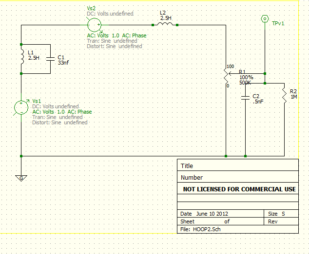 But the results I'm getting don't seem to make much sense. This is sweeping the cap value from .5nf to 60nf: 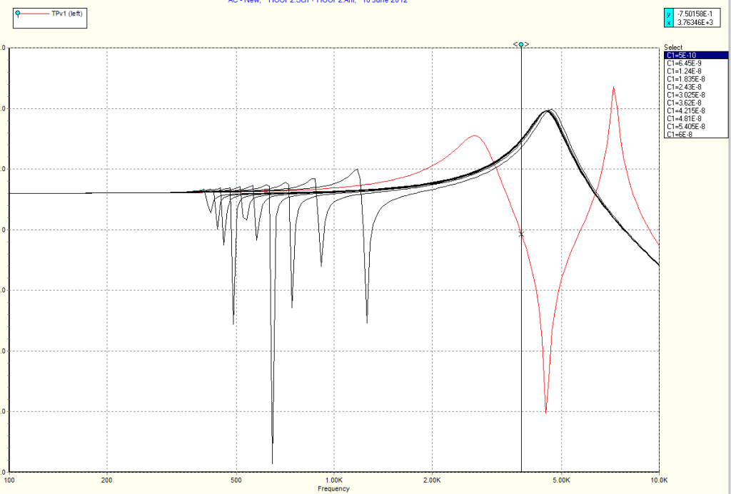 If I'm reading this right, the cap value does move the "trough" but it seems like the frequency range in which it does so is very low. This may not be a good way to test this, probably it would be more helpful to Rune to do some cap-substitution testing external to the guitar. |
|
|
|
Post by JohnH on Jun 10, 2012 17:26:43 GMT -5
newey - the model is working (good work!) , but I think there is not enough of the other impedances modelled that occur in reality, such as pickup resistance and also the tone pot. These resistive loads tend to smooth things out and spread the peaks. I previously set up such an analysis, so here's my version, posted on a thread last year:  This plot shows up to 33nF bypass cap, but theres no substitute for listening tests. I tend to use 47nF for this, but results will depend on the pickups too. John |
|
|
|
Post by reTrEaD on Jun 10, 2012 23:22:22 GMT -5
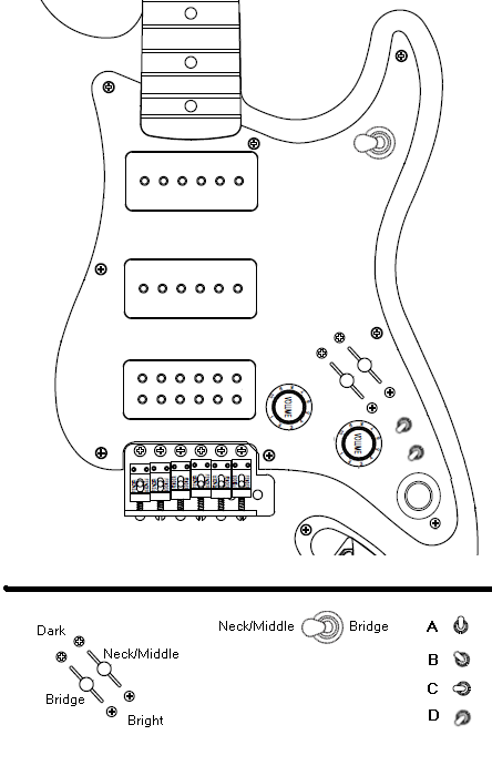 Some more questions. 1 - From neck to bridge, will the polarities be NSNS or SNSN? 2 - Will the buffer bypass switch be DPDT or 4PDT? 3 - Will the buffer bypass switch move in axis A, B, C, or D? 4 - Will the buffer be enabled or bypassed, when the toggle matches the position shown in the axis drawing? 5 - Will the kill switch move in axis A, B, C, or D? 6 - Will the sound be enabled or killed, when the toggle matches the position shown in the axis drawing? 7 - Does your pickup selector look like any of these pictures?     |
|
|
|
Post by JohnH on Jun 11, 2012 1:34:14 GMT -5
Here's a go at some of the wiring - downstream of the 5-way switches:  Buffer not included yet. I can email anyone who wants to play with the Word file - send me a pm if so. John |
|
|
|
Post by Runewalker on Jun 11, 2012 5:50:04 GMT -5
Hey John, thanks for whipping out the mouse and inserting some wires.
Per RT's suggestion I re-cast the previous drawings in .png and also inserted the jack and buffer.
I'll PM you on both the file and request then try to peel of some time after work tonight to work on them. Since you are still in the future down under, I am sure you could tell me now what tonight holds for me.
thx
RW
|
|
|
|
Post by Runewalker on Jun 11, 2012 6:28:47 GMT -5
Some more questions. 1 - From neck to bridge, will the polarities be NSNS or SNSN? That I am not sure of yet as I have to actually sit at the bench and test the P90's. For these purposes the Tone Zone P90 (ff) is a Dimarzio and this is the standard colors I have for them: Screw Pole coil - SouthStart – Green
Finish – White Slug Pole CoilStart – Red
Finish – Black As you noted previously, both coils have adjustable coils. I wrote Dimarzio to confrim: that the one with Green and White wires is indeed the South coil;
and the one with the Red and Black wires is the North coil?
Duncan is pretty good about responding ... not too sure about Dimarzio. We will see and I will report back. 2 - Will the buffer bypass switch be DPDT or 4PDT? If I need a 4PDT I am not sure I could fit it without carving up the cavity. Before I started drawing I did not believe I could shove all this in the standard strat rout. However I was surprised at how everything fit, at least on paper. So I was a little thrilled that the wood work was restricted to the pup selector channel. Sounds like you are thinking I need a 4PDT? If so, more carving is required. I have been toying with moving the kill switch closer to the pup selector anyway. Tom Morello time, without the preachy politics. 3 - Will the buffer bypass switch move in axis A, B, C, or D? I am guessing more like C. 4 - Will the buffer be enabled or bypassed, when the toggle matches the position shown in the axis drawing? Enabled (on) 5 - Will the kill switch move in axis A, B, C, or D? C. 6 - Will the sound be enabled or killed, when the toggle matches the position shown in the axis drawing? Enabled (on). 7 - Does your pickup selector look like any of these pictures? Before I guess, let me call up Son-o. He has my box of switches. Very thorough questions. |
|
|
|
Post by reTrEaD on Jun 11, 2012 11:39:19 GMT -5
Very thorough questions. That's probably the limit of my usefulness to this project. I'm pretty good at visualizing the details that can slow things down. Defining which items need to be addressed can help avoid roadblocks that might occur. This drawing is moving in a different direction than I had imagined, but it's not necessarily a bad thing. While gorgeous to the eye, the parts aren't in the same orientation they would be in the pickguard. So you'll need to be careful when doing the actual wiring. Contacting manufacturers is good. Often it leads to them providing better info in the package with their products. But I'd still double-check with a compass (or known pickup) and the screwdriver test. Even if it turns out that the south coil of the TZ is white/green, how will you know which physical location the south coil is in? From the outside, both sets of polepieces look the same. Since opposites attract, it would be easy to determine using a compass. The north needle of a compass will point to the top of the South polepieces. Likewise, you can use a scope or meter connected to one coil of the pickup and place a screwdriver tip on the polepieces with the shaft of the screwdriver above some of the windings. When you abruptly pop the tip up from the polepieces, it will induce a pulse into the windings. There might be a slight pulse induced in the other coil, but the difference in magnitude will be unmistakable. |
|
|
|
Post by reTrEaD on Jun 11, 2012 12:11:53 GMT -5
Sounds like you are thinking I need a 4PDT? Not necessarily. If the buffer you are using has a low current requirement, a DPDT will be just fine. But if it's hungry and seldom used, it would make more sense to switch the power off when bypassed. If you choose to go that way a 3PDT would be necessary. But those are less common than a 4PDT. I have been toying with moving the kill switch closer to the pup selector anyway. Tom Morello time, without the preachy politics. Killswitches are almost worthy of their own thread. If I have some time, I might do just that. For now, suffice to say there are a several different options available in a minitoggle form factor. The simplest is: push one way for sound push the other for kill. SPST or better required. You could use an ON-OFF-ON switch so kill would be at either direction of the travel. Sound would be in the middle. Twice as many kills for the same number of strokes. SPDT on-off-on or better is required. Alternately you could use an ON-ON-ON switch and put the kill in the middle position. DPDT on-on-on or better is required. Or you could use a momentary (spring return). Push in one direction to kill, but the toggle springs back to sound on its own. I could go on, but it might get messy. |
|
|
|
Post by JohnH on Jun 11, 2012 15:31:57 GMT -5
Retread - you could very usefully be a checker of wiring diagrams, particularly once the 5-ways get wired.
RW - if you want to shift the two 5 ways into a nearer alignment to that intended, keeping the rest the same, I can paste the new version onto my file without a do-over. Move the kill switch too if you wish.
These wiring diagrams dont need to be exactly in proportion - usually its better to space things out a bit more than reality. But its good if approximate relationships are right, so the best choices can be made about which order to link up the lugs.
cheers
John
|
|
|
|
Post by reTrEaD on Jun 11, 2012 16:31:41 GMT -5
I'd be glad to lend a set of eyes to the wiring drawing. The more the merrier. Given the complexity of this, there will be plenty of opportunities for errors. Hopefully we can recruit Newey and some others for the proofreading too. These wiring diagrams dont need to be exactly in proportion - usually its better to space things out a bit more than reality. But its good if approximate relationships are right, so the best choices can be made about which order to link up the lugs. I agree 100%. Scale is low on the list of priorities. Approximate position of the components, relative to one another, is a little higher. More important, imho, is the orientation and viewing angle. I think the easiest way is to view everything as you would be looking at the backside of the pickguard. Most of your drawings are like that. Iirc, the two volume strat was a good example of this. You took the necessary liberty of "folding" the DPDT section of the pots over to allow an easier view. This made for a very useable diagram. As pretty as the PP pots are in this drawing, they complicate matters a bit. Since they are shaft end up, they will appear different in the drawing than they do when installed in the pickguard. This will require a large mental adjustment when doing the actual wiring. If you are going to use those in the drawing, do you think it might make sense to flip them upside down? The dual concentric tone pot probably doesn't look like that, but I think displaying it that way does make for an easier drawing to view. A bit less cluttered than if the lugs have the correct orientation. And it only takes a very small mental adjustment to reconcile the drawing to the actual wiring. I think the way you did those in the two volume strat was better, but this isn't bad. |
|
|
|
Post by Runewalker on Jun 11, 2012 18:02:32 GMT -5
Gee RT.... "Since they are shaft end up..." I'm not sure that will get through the censors, so I will definitely change their orientation. that was just my mistake. On the orientation.... These complicated designs get so snakey I was trying to add space for drawing while making a general nod to placement. Here is what things were looking like adapting John's pix and before the change in PP orientation. I'll fix that later knowing this is full of mistakes... 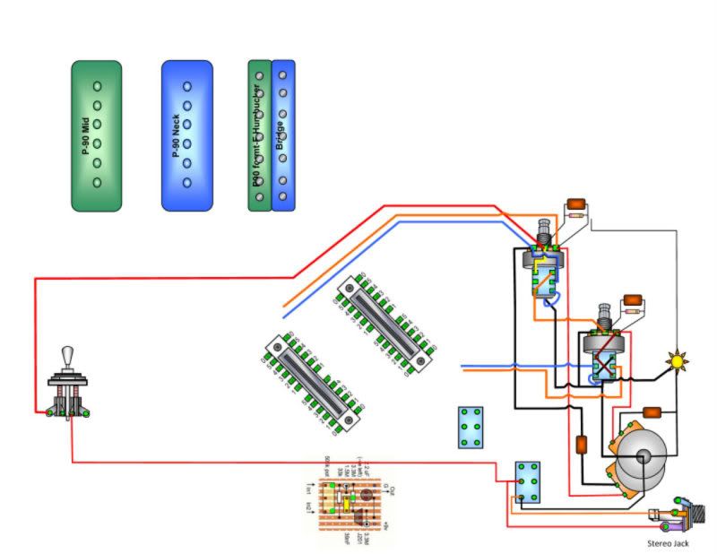 |
|
|
|
Post by JohnH on Jun 11, 2012 19:55:50 GMT -5
Yes, these wiring diagrams are always done viewed from the back, as seen through the fumes of solder smoke while wiring it.
The pp pots are tricky to show, but RW’s rendering of them has worked before, and I see no problem with it, you just have to keep a 3d perspective.
On buffers, I reckon a dpdt, without power off, for reasons stated previously. The JFet buffers (RW has some) are very low current indeed.
The tone pots, as shown by me, the B tone will be the rear part, which I assume becomes the outer smaller knob on the concentric set.
With regard to order of selections, did any of the plots or sound samples lead to a change in view of the order of them? I’m thinking of the bypassed sounds, where the N/M version on the Ibanez Strat sounded like a brighter variation of full series, where the Gibbo LP bridge pup made a sound nearer to the complete single coil cut. I think both switches should have the same order, but Im now in two minds as to whether to suggest.
Series, series bypassed, para, coil1, coil2,
or
Series, para, series bypassed, coil1, coil2.
John
|
|
|
|
Post by newey on Jun 11, 2012 22:30:16 GMT -5
As I have pointed out in another context, whichever selection will be used less should occupy the middle position, as accessing the middle position means a purposeful selection, rather than a flick in one direction or the other.
At least where switching "on the fly" is concerned, a flick to the left or right on a lever switch is more likely to end up on 1 or 2, or on 4 or 5, respectively, than it is to end in the middle.
|
|
|
|
Post by JohnH on Jun 12, 2012 5:44:48 GMT -5
As I have pointed out in another context, whichever selection will be used less should occupy the middle position, as accessing the middle position means a purposeful selection, rather than a flick in one direction or the other. At least where switching "on the fly" is concerned, a flick to the left or right on a lever switch is more likely to end up on 1 or 2, or on 4 or 5, respectively, than it is to end in the middle. That is a good perception. In this case, I think it might add weight to the idea that the series/cap bypassed setting is in the middle, it being the least standard setting and the last to be added, to use up the additional position on a 5-way, instead of 4-way switch. |
|
|
|
Post by Runewalker on Jun 12, 2012 6:51:43 GMT -5
As I have pointed out in another context, whichever selection will be used less should occupy the middle position, as accessing the middle position means a purposeful selection, rather than a flick in one direction or the other. At least where switching "on the fly" is concerned, a flick to the left or right on a lever switch is more likely to end up on 1 or 2, or on 4 or 5, respectively, than it is to end in the middle. That is a good perception. In this case, I think it might add weight to the idea that the series/cap bypassed setting is in the middle, it being the least standard setting and the last to be added, to use up the additional position on a 5-way, instead of 4-way switch. Newey makes a good point. Since you don't want to disrupt those critical performance moments with too much fiddling around trying to find the mid position, then when I play arena shows with 40,000 screaming fans I will be sure to just stick with the Les Paul with 3 positions. My other venue in my man cave playing to ... well ... the windchimes on the back porch gives me more fiddling around latitude. JH asks: "With regard to order of selections, did any of the plots or sound samples lead to a change in view of the order of them? I’m thinking of the bypassed sounds, where the N/M version on the Ibanez Strat sounded like a brighter variation of full series, where the Gibbo LP bridge pup made a sound nearer to the complete single coil cut. I think both switches should have the same order, but Im now in two minds as to whether to suggest.Series, series bypassed, para, coil1, coil2, or
Series, para, series bypassed, coil1, coil2."
Yes, I also have been having that debate with myself. Since that position is likely to be used mostly with the N/M combo (at least by me), and it's attenuation is subtle compared to standard Local Series, I select: Series, series bypassed, para, (inner) coil1, (outer) coil2 ... top to bottom when holding the guitar in playing position. From the PSpice graphs it looks like some decision making needs to be considered on cap value, depending on what intent is being dialed up. I need to think about that. RW |
|
|
|
Post by Runewalker on Jun 12, 2012 6:54:50 GMT -5
On the drawing....
I need to do some biz travel (whoever came up with this "working for a living cr*p?), so won't get back to the wiring diagram for a day or two. Man this thing has a lot of wires. Spaghetti bowl.
I am inverting the PPs as suggested by RT, so ignore that previous wiring drawing ... I'll fix it later.
RW
|
|
sonosonny
Apprentice Shielder

Posts: 33
Likes: 0
|
Post by sonosonny on Jun 12, 2012 9:24:00 GMT -5
Pics of Rune’s full size Gibby 3 way to be used in this build.Installation depth required from bottom of pickguard to bottom of switch measures 7/8” or 2.4 Centimeters per my measurements. It appears to be similar to or exactly like the third selection out of the four in ReTread's post above. 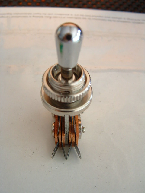 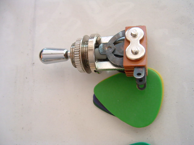 The traffic and knowledge produced by this topic is phenomenal. I am surprised that this "atmoshperic" topic is not filed under Truly Nutzoid Schemes....Highest Regards, Son-O
|
|
|
|
Post by reTrEaD on Jun 12, 2012 10:27:40 GMT -5
I'm not sure that will get through the censors Oh you... The tone pots, as shown by me, the B tone will be the rear part, which I assume becomes the outer smaller knob on the concentric set. The inner shaft controls the element farthest from the pickguard. Iirc, Rune wanted that to control the neck/middle? At least where switching "on the fly" is concerned, a flick to the left or right on a lever switch is more likely to end up on 1 or 2, or on 4 or 5, respectively, than it is to end in the middle. Imho, the 1 and 5 positions are prime real estate. With a Gibson toggle or to a lesser degree a Tele 3-way, the middle position isn't hard to hit at all. But with a 5-way, things are quite different. 2, 3, and 4 are all a bit fidgety. I suppose you could make a case for 2 and 4 being a little easier to hit than 3. From the PSpice graphs it looks like some decision making needs to be considered on cap value, depending on what intent is being dialed up. Yeah, it stands to reason that with a small cap it won't sound much different than a series HB and with a huge cap it won't sound much different than a single. Getting a "single with a fat bottom" (please, no remarks about the girls at the bars I frequent) sound might take some trial and error with the cap value. I am surprised that this "atmoshperic" topic is not filed under Truly Nutzoid Schemes.... That section is for finalized projects. I'm sure a new thread for this project will appear there in a month or two.  |
|