|
|
Post by ChrisK on Dec 17, 2007 22:34:18 GMT -5
THE BLEND POTA true BLEND pot since, at the center detent, both sections are full-on as in real low (i.e. a few Ohms) resistance. It is designed to BLEND a signal from one of two pickups while presenting a constant signal from the other pickup. It can ideally blend pickups and the performance is excellent in that the typical parallel interaction between two passive pickups is preserved by the low resistance in the center detent position. Only at the extremes of rotation is any one pickup fully off. Both sections have a linear taper in this example. The top chart is the absolute resistance (the different elements in this example have different resistance tolerances, which is typical). The bottom chart are the normalized ratios as a percentage of full scale. 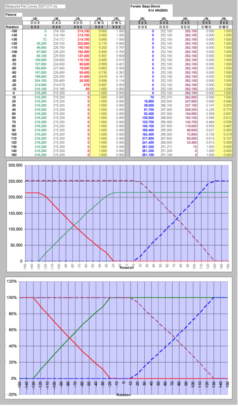 ___________________________________________________________________________________________ THE PAN POTWhile misrepresented by virtually ALL guitar parts sellers as a Blend pot, IT IS NOT. It is a true PAN pot since, at the center detent, both sections are not full-on as in real low (i.e. a few Ohms) resistance, but still have substantial resistance. It is designed to PAN a signal between two channels while presenting a relatively constant signal sum (as in combined level). While it can be used to blend in pickups, the performance is lacking in that the typical parallel interaction between two passive pickups is prevented by the excessive resistance in the center detent position. Only at the extremes of rotation is any one pickup fully on. Both sections have a non-linear taper necessary for the constant level function. However, it is NOT a true log taper, but instead made up of two to possibly three piecewise linear segment approximations. The top chart is the absolute resistance (the different elements in this example have very similar resistance tolerances, which is atypical). The bottom chart are the normalized ratios as a percentage of full scale. 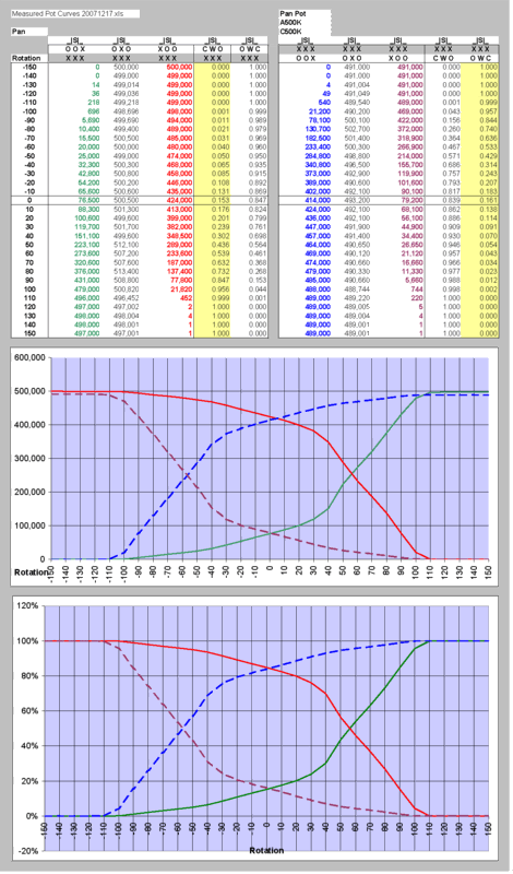 .....................a 500K PAN pot.....................a Fender 250K BLEND pot...............a Fender 500K BLEND pot... 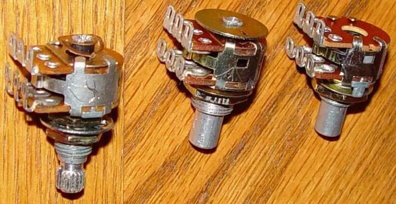 The test scale and knob; 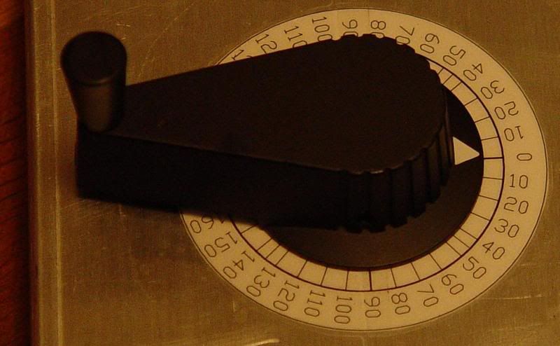
|
|
|
|
Post by flateric on Dec 18, 2007 10:51:52 GMT -5
Great info, thanks Chris, my fears confirmed. Now since it appears in practice that the 'blend pots' sold by guitar parts retailers are in fact pan pots with small (but significant) resistance at the centre detent, how do you go about making sure you buy a proper blend pot? Some people offering pan pots carry on assuring you it is a blend pot.
|
|
|
|
Post by sumgai on Dec 18, 2007 13:46:49 GMT -5
Chris, Ah yes, this is what I was asking for, mercy buckets! ;D But, those graph images are png format, and they are HUGE! They take a considerable amount of time to d/l, and for our members who are not on T1 or better, that's a lot to ask. Any possibility you could perhaps either shrink them, or convert them to a format that provides the same info with a smaller file size? Please??  Donkey sh.... ;D sumgai |
|
|
|
Post by sumgai on Dec 20, 2007 21:04:16 GMT -5
Ah, much better! Thanks!! ;D
sumgai
|
|
|
|
Post by ChrisK on Oct 14, 2008 13:20:28 GMT -5
newey had mentioned to me that GuitarPartsDepot.com claimed to have blend pots, so I asked them. While I have not verified this info, they state the following: "Hello, Yes, our blend pots are true blend. Please let me know if you need anything else, or have any more questions. Thanks for visiting our site! Best Regards, Nick Wheaton (866) 631-4473 www.GuitarPartsDepot.comwww.myspace.com/guitarpartsdepot"
|
|
|
|
Post by newey on Mar 26, 2009 21:12:13 GMT -5
Sorry, nope. Anyone want some Pan Pots? After long searching, I have been unable to identify any true Blend pots from any of the online sellers, apart from the OEM Fender ones ChrisK posted above. At least, there were no others that I was willing to bet my purchase dollars on, after my experience with the above order. Rumors of secret stashes, however, abound.  |
|
|
|
Post by sumgai on Mar 26, 2009 21:42:57 GMT -5
newey, Rumors of secret stashes, however, abound.  If those 'secret stashes' involve either: 1) Mil-spec tolerances; or 2) Wholesale quantities only; or 3) Purchase in another city is required then the word is not "abound"..... it should be "aboond".  HTH sumgai |
|
|
|
Post by ChrisK on Mar 26, 2009 22:12:52 GMT -5
Well, ya know Sparksters, I could do another bulk order of these things. I have aboot 3 of one value and 7 of the other left. I gave newey one of each last fall, but my supply is GeDwindling. But then, I'd have to send them out and hassle with getting money sent. There are mysterious places called "Fender Authorized Repair Centers". These Places are Authorized by Fender to Repair their stuff. As a result, they are Authorized by Fender to order factory parts to Repair their stuff. There might even be a secret list of these mysterious places, and their planetary locations. The 250K bass BLEND pot; 0049441000  The 500K bass BLEND pot; 0056097000  Having been motivated to get off of my duff in the relatively distant past during my planetary search for non-panning pots, I looked at various Fender bass guitar wiring (and part list) drawings (these are free to the world if you just go look at them) and easily discerned the Fender part numbers for these aforementioned species potamus blendus. (One CAN learn a lot simply by looking aboot.)  |
|
|
|
Post by sumgai on Mar 26, 2009 22:59:43 GMT -5
Ya know, my local GC is the area's Fender Authorized Repair Center....... Several years ago they were without a tech, and asked me to "interview" for the job. I said 'No thanks, I like retirement'. In retrospect, perhaps I was a bit hasty. Between these pots and those S-1 doo-hickies, I could have made several GuitarNutz happy.  I'm not saying anything here, I'm just sayin', ya know..... |
|
|
|
Post by ChrisK on Mar 28, 2009 0:28:01 GMT -5
Well, that bodes, well.............if I take a guitar in there is it money, well, spent?;D ;D ;D Ya know, this guy HAS the S-1 switches as well as the S-1 knobs aboot 90% of the way down the " holy crap, they put every freakin' part in the same html page" web site. www.darrenriley.com/fenderparts.htm"Holy freakin' potomakowski Batman, they even have the 500K PAN pot (yup, in the true spirit of the whole Fender tremo'Leo guitar'aroonie, amp vibratowski we can't tell our burro from a burrow debacle they call a true BLEND pot a PAN pot).  Of course, they do not list the 250K unit. A clever sort might visit the Fender (a.k.a Mr. Gearhead - but not in these times) site to determine that the 0056162000 unit is indeed a 250K BLEND PAN BLEND, oh, whatever, pot.  . . |
|
|
|
Post by newey on Mar 28, 2009 10:30:16 GMT -5
GuitarPartsResource also has these, described as "pan pots". The part number for the 500K one matches ChrisK's reference, while the 250K one bears the same part number as the one on Darren Riley's site, which is different from the one cited by Chris as the correct part number for 250K ones. Chris referenced these as "bass" parts, is it possible the 250K one for a guitar would be a different part number? I would think it would be the same, unless the taper is different. Does anyone know whether Fender ever used pan pots as OEM on anything? If not, one could perhaps assume all Fender OEM blend pots are, in fact, true blend, even if designated as "pan" pots. EDIT:BassPartsResource, the sister site to the above link, lists the same 2 parts numbers for the 250K and 500K so I guess there's no different part number if it's designated as a bass pan pot.
|
|
reveriesof
Rookie Solder Flinger

Posts: 4 
Likes: 0
|
Post by reveriesof on Mar 28, 2009 17:38:29 GMT -5
has anyone looked into sourcing true blend pots from outside the guitar parts universe? from the likes of mouser for instance? what characteristics would one look for? in his DIY Projects book, which i have the luxury of viewing online thru my campus library, craig anderton discusses panpots if briefly and elliptically..
A true panpot usually has a log taper for one element and an antilog taper for the other element because this gives the best ''feel" and most even panning response (we don't need to explain why, just take my word for it). Log/antilog taper pots are very rare, but there's a workaround: use an ordinary dual-ganged linear taper pot and add "tapering" resistors R1 and R2. These should equal 20% of the pot's total resistance; adding them as shown changes the pot taper to a log/antilog curve.
i'm not sure if he is consciously referring to pan viz blend pots as in Chris's terminology. here's his schematic, which includes a funky tone switch apropos of nothing...  are fender's blend pots log/antilog then, or some other configuration entirely? does this scheme (minus the tone switch) get us any closer to true blend? my vague understanding leads me to suspect that those tapering resistors are going to cause the very same tone drag at the center detent symptomatic of other pan pots (in which case shame on craig!) for the record, i implemented the anderton panpot in a gorgeous 72 reissue thinline tele i had warmoth mill from rosewood. all pots (vol, tone, dual pan) are 500k and the configuration makes my rio grandes sound quite dark and boomy. but i've never heard them in a standard configuration, so i cant judge too well how much of that would be attributable to these pickups and this particular axe. i'll take a stab at the fender blender if the local tech can order one for me (not into paying darren 7 bucks to ship 1 pot!) but to return to my original point... surely there are other applications for this type of pot, someone besides fender must surely have made them? but i get overwhelmed shopping from mouser even when i know what i'm looking for! stewmac has a page on blender wiring; safe to assume they actually sell pan pots? |
|
|
|
Post by ChrisK on Mar 28, 2009 18:58:30 GMT -5
Craig is referring to PAN pots in the only accurate/viable terminology. A PAN pot is comprised of a log and anti-log (both are in linear piecewise approximation form) driven by the same shaft. If you look at the pic of a pan pot in my initial post to this thread, you will see that, aside from differently formed terminals, both elements are identical, with them facing each other. This gives the complementary curves. If you look at the plotted response curves, you will see the log/anti-log response. Oh, crap, wait! Don't use the bass ones that I gave you in a guitar, newey. ;D ;D No, they are half-sided dual linear elements as described in my initial post to this thread. You will see that, aside from differently formed terminals, both elements are identical, with them facing each other. This gives the complementary curves. If you look at the plotted response curves, you will see the linear half-sided response (from center to CCW one element is in play while the other remains in resistive position. From center to CW the other element is in play). The tone switch is in lieu of a tone control. It emulates the Esquire/Tele cap cut bass'ish mode before the release of the Precision Bass. Yep, it attempts to emulate a PAN pot. Immaterial. Rosewood would make a dental drill sound dark and boomy.   ;D ;D I never understood the attraction of a rosewood solid body guitar aside from someone swinging one aboot on a rooftop 40 years ago.   My Bro' in-law wanted me to put the Rio Grande Dual Calibrated Strat set into one of his AmStd Fender Strats because he wanted that Texas tone. I did. He says that they're too dark sounding and could I apply some of my engineering knowledge to brighten them up. What's the difference between in-laws and outlaws; you can hang outlaws.....  No, not generally. I've not seen any high value ones in my 30+ years as an electrical design engineer. I have access to Mil-Spec surplus channels and have not seen anything of interest. In years past, there were more of the customs available surplus. In today's embedded controls world, custom pots are moot; software rules (the look-up table). Because, hardware is cement and software is Velcro.....  These pots come under the classification of custom. These are OEM specified and ordered in volumes typically of 1,000's or 10,000's at a time. They also cost about $1 to $3 in said volumes. When I bought my last bunch of the Fender units, I paid $3 and $6 respectively (of which I don't remember) in 10's. I use some custom pots at work and have had customs made for me that I use in my guitars. The prototype lot (10) of the latest one for guitar use has shipped and I should have them next week. But then, I'm in that business. Yep. |
|
|
|
Post by sumgai on Mar 28, 2009 19:38:37 GMT -5
Does anyone know whether Fender ever used pan pots as OEM on anything? Several models of the Jazz bass have had a blend pot. It comes and goes, following whatever fad Fender has targeted for that day.  sumgai |
|
|
|
Post by ChrisK on Mar 29, 2009 21:43:59 GMT -5
|
|
|
|
Post by sumgai on Mar 30, 2009 11:45:14 GMT -5
Chris, I don't have the canonical Fender Jazz Bass catalog in front of me, but I do know (because my cousin has one of 'em) that there were a few models that used the blend pot as the "pickup selector". Still only the one tone (treble cut) pot, with a smaller knob, so you'd never know from just looking at it. Too bad he won't let me dissect it so's I might get a look at the part numbers....  sumgai |
|
|
|
Post by ChrisK on Mar 31, 2009 19:51:12 GMT -5
I'm not surprised. There might be a tone issue with having three pots in parallel though (the two sections of the blender and the volume pot).
Having had both the passive two volume single tone versions as well as the blender-based active tone control ones, I still prefer the blender as on my Urge II bass.
(And dang, it has three pickups!)
|
|
|
|
Post by ashcatlt on Oct 22, 2014 18:39:34 GMT -5
This thread hasn't been posted to in a while, and maybe this would be more appropriate somewhere else, but I was looking around for something, and came across Bournes blend/balance pots which appear (according to the data sheet) to be actual true blend pots per chrisk's definition above for less $3 a piece, which is super cheap compared to any of the guitar parts stores listed above. 500K Knurled Shaft250K Plain Shaft500K Plain Shaft |
|
|
|
Post by sumgai on Oct 23, 2014 3:41:20 GMT -5
Nice find, ash!  If the taper curves shown in the Datasheet are correct, then these truly are the correct parts for our desired applications. And they cost less than a pack of cigarettes, too - what a deal! |
|
|
|
Post by ashcatlt on Oct 23, 2014 10:41:48 GMT -5
I'm not sure that doesn't say more about the absurd price of cigarettes nowadays, but yeah. Like 20% of the going rate at other places.
Unfortunately, what I was looking for was concentric pots. I'd have thought those more likely to be found at mouser, but I sure couldn't.
|
|
Deleted
Deleted Member
Posts: 0
Likes:
|
Post by Deleted on May 12, 2019 11:24:19 GMT -5
Never tried a Blend pot, How about 1M POT, cut in the middle of the Track, and a second PCB pot that has a  So dual pot, Top say 1M Ohms, Small Knife Cut in the Middle to split it (Must be LIN) so we got two 500K Ohms put that work on the halfs POT: LUG ONE Neck, LUG TWO Common, LUG THREE Bridge PCB: LUG ONE Bridge, LUG TWO Common, LUG THREE Neck |
|
|
|
Post by sumgai on May 14, 2019 12:30:07 GMT -5
bunny;
It's always a good idea to experiment, given that safety is of paramount concern. (Here I'm speaking of things like electrical shock, etc.) If the only likely harm is to one's wallet, then I'm up for all such endeavors. Still, I'm sorry to have to say that what you show (putting a resistance between the pup and the output) has been tried before, with the following results:
a) reduced output;
b) the dreaded Tone Suck; and
c) unpredictable resolution (due to tolerances in the various resistance values).
Don't let me dissuade you from trying this, I'm just pointing out that a bit of research might enhance your designs. I recommend that you Search (in the menu bar towards the top of this page) for "blend pot" in the box that says "All of the words". Wherein, you'll find things like this circuit:
guitarnuts2.proboards.com/thread/7450/blend-pot
and lots of other Nutzy stuff as well. 
HTH
sumgai
|
|
|
|
Post by reTrEaD on May 14, 2019 14:19:06 GMT -5
@angelsbunny , that's very creative thinking you're using with the second wafer maintaining full contact between one pickup and the output while the other pickup is connected to the output through a varying resistance. It gets half the job done, but the other half (the pot element providing the variable resistance) is doing all sorts of wrong things!
Yes, you can change the blend by introducing resistance in series with just one pickup at a time in a circuit where the two pickups are in a parallel configuration. This can work. But the amount of resistance you should add in series doesn't track properly with any commonly made single pot element.
Let's compare what would happen with what you're suggesting to what we need to happen.
Your configuration:
As we move just slightly toward the Neck end of the of the rotation, the Neck pickup maintains full continuity to the output. Good! But the Bridge Pickup is now disconnected on the second wafer. It's only path to the output is through the resistive element. The problem with that is the amount of resistance is half the total value (500k). That means it is for all intents and purposes, fully out of the blend. Not Good!
As we continue moving toward the Neck end of the rotation, the resistance in series with the Bridge pickup is reduced until it finally reaches zero at the end of the rotation. Now the Bridge pickup is blended in equal amount to the Neck pickup. Not Good!
What we need:
As we first move from the center of rotation toward the Neck end of the rotation, we need the resistance in series with the Bridge pickup to be at minimum and increase until it reaches maximum value at the Neck end of the rotation.
Also, the ideal situation would be for the rate of change of resistance to be very 'slow' near the center of rotation and 'rapid' near the end of rotation.
You won't be able to modify a normal potentiometer's resistive element to achieve either of these goals. Instead, it would make more sense to have two specialized elements, one for each pickup.
One element maintains full continuity through half it's rotation, then begins to gradually add resistance past the midpoint and accelerates the rate of added resistance as we reach the end of the second half of rotation.
The other element does the same sort of thing but in the opposite direction of rotation.
|
|
Deleted
Deleted Member
Posts: 0
Likes:
|
Post by Deleted on May 15, 2019 9:21:57 GMT -5
bunny;
It's always a good idea to experiment, given that safety is of paramount concern. (Here I'm speaking of things like electrical shock, etc.) If the only likely harm is to one's wallet, then I'm up for all such endeavors. Still, I'm sorry to have to say that what you show (putting a resistance between the pup and the output) has been tried before, with the following results:
a) reduced output;
b) the dreaded Tone Suck; and
c) unpredictable resolution (due to tolerances in the various resistance values).
Don't let me dissuade you from trying this, I'm just pointing out that a bit of research might enhance your designs. I recommend that you Search (in the menu bar towards the top of this page) for "blend pot" in the box that says "All of the words". Wherein, you'll find things like this circuit:
guitarnuts2.proboards.com/thread/7450/blend-pot
and lots of other Nutzy stuff as well. 
HTH
sumgai
i will try and read all, will take me a few days with work and slow reader (why i type funny too) I could PAT Test the POT if you like, uk is 240v (even tho we should be 220v to bring in line with EU) but i do have my Electrician qualifications and did pass the UK PAT qualifications. The Change isnt much from what the POT was designed for in the first place. THEORY is that while one Pickup has 0-500K the Other Pickup will be on my "Wafer" side of the Pot doing 0 Ohms for the other Pickup. And then all change over, when the pot is at Mid Point (note the funny dual track lines) Both Pickups come in to play with Zero Resistance. SHOULD!!! look like this  "Path of Lease Resistance " Borg Queen NB Graphics Pinched from ChrisK   dam it .. wrong way around 0 to 500K to 0 .. should be 500 to 0K .. 0 to 500K mmm sorry ..reTrEaD |
|
Deleted
Deleted Member
Posts: 0
Likes:
|
Post by Deleted on May 15, 2019 9:41:27 GMT -5
Your configuration:As we move just slightly toward the Neck end of the of the rotation, the Neck pickup maintains full continuity to the output. Good! But the Bridge Pickup is now disconnected on the second wafer. It's only path to the output is through the resistive element. The problem with that is the amount of resistance is half the total value (500k). That means it is for all intents and purposes, fully out of the blend. Not Good! As we continue moving toward the Neck end of the rotation, the resistance in series with the Bridge pickup is reduced until it finally reaches zero at the end of the rotation. Now the Bridge pickup is blended in equal amount to the Neck pickup. Not Good! MID Point is the Focus point, This should let both Pickups Go Via the Strange dual Track bit on My Wafer.
As we turn LEFT towards the NECK, it should take off My Wafer for the NECK and join back on to the POT 500K, as this is its only Path, (Note starts off at 500K, wasnt want i wanted, so i will look to change that). The BRIDGE keeps going via My Wafer. As it turns more to the LEFT the Resistance should drop as it goes from INPUT of the POT to the COMMON on the POT (Another Design fault, when fully turned, 0 Resistance on the NECK, and the Bridge also has 0 Resistance going via My Wafer)
What we need:As we first move from the center of rotation toward the Neck end of the rotation, we need the resistance in series with the Bridge pickup to be at minimum and increase until it reaches maximum value at the Neck end of the rotation. Also, the ideal situation would be for the rate of change of resistance to be very 'slow' near the center of rotation and 'rapid' near the end of rotation. You won't be able to modify a normal potentiometer's resistive element to achieve either of these goals. Instead, it would make more sense to have two specialized elements, one for each pickup. One element maintains full continuity through half it's rotation, then begins to gradually add resistance past the midpoint and accelerates the rate of added resistance as we reach the end of the second half of rotation. The other element does the same sort of thing but in the opposite direction of rotation. I need to READ this a bit more so "BRB"

as need to go from the COMMON to a Leg, so one Pot for NECK and one for BRIDGE still cut in the middle say
>Just roll with it, to see if can be designed and then see if any way to save on, ie I dont want to use a QUAD pot but cant see any other way around it. There are such things as i played with one years ago<
This also means got 2 more places for a NEW Wafer, and i think will need it to fix the FULL Turns (Left/Right) problem
Before MAKING Wafers, i used to use Silver Track Paint.. But i fear the Pot will Rub it off over time |
|
|
|
Post by reTrEaD on May 15, 2019 11:26:43 GMT -5
Thinking on how to change the POT Value so it does go from 0 to 500K, Means QUAD POT 
as need to go from the COMMON to a Leg, so one Pot for NECK and one for BRIDGE still cut in the middle say
>Just roll with it, to see if can be designed and then see if any way to save on, ie I dont want to use a QUAD pot but cant see any other way around it. There are such things as i played with one years ago<
This also means got 2 more places for a NEW Wafer, and i think will need it to fix the FULL Turns (Left/Right) problem
Before MAKING Wafers, i used to use Silver Track Paint.. But i fear the Pot will Rub it off over time A four-layer pot seems like overkill. I share your fears about Silver paint. It isn't durable and would likely be damaged by the friction of the wiper traveling over it. Copper plating might work, though, I used MS Paint to edit a drawing ChrisK posted in different thread, retaining only the part which represents the internals of a Fender blend pot. Only two specialized wafers are being used. 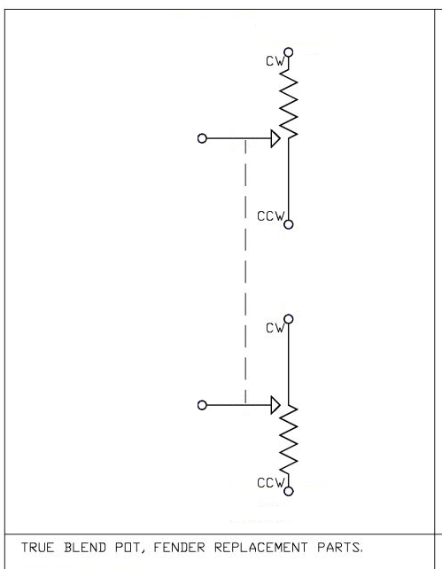 |
|
Deleted
Deleted Member
Posts: 0
Likes:
|
Post by Deleted on May 16, 2019 7:44:53 GMT -5
The problem is, because i need it to go from 0-500K, three ways to do this 1) -150' - 000' be ZERO Ohms 000' - 150 Resister 0-500K. With Lug ONE Input, Lug Two Output, Lug Three N/C >Needed for both Pickups, NB would look the same as one is Flipped over when in case< 2) Two Resister Pot, both cut in the middle.. Lug One N/C, Lug Two Input, Lug Three Output A Cross Over Wafer Design Lug One PickUpA, Lug Two Output, Lug Three PickupB >NOTE this is 3! Wafers 2xPot and 1xDesigned< 3) One Resister Pot, Cut in the middle, Lug One Output, Lug Two LINK, Lug Three Output This will have Two Cross Over Wafers (One to Sort out who gets the Resister pot, and one to do the ZERO Ohms bit) a) Lug One PickupA, Lug Two LINK, Lug Three PickupB b) Lug One PickupB, Lug Two Output, Lug Three Pickup A This is all TOP View, the Layout will have to change i think as the "Pots/Designs Wafers" sit Facing each other Personally i dont want to do 3 Pots (would be in a Quad case) think its a waste and too much, would mean doing type ONE! means cutting away/painting over (adds High) and replacing with Silver Paint (It dose rub off so would need conductive sealer too!!) or Some form of Copper strip (Curved!) at the moment thinking of the copper way, i got SLUG Tap (what is said to be copper, ill see if it conductive) after that is a think copper glued down (I do think i would have to take some of the POT PCB board down a bit to get the HIGH) IT WILL Be Fun to Try .. FLY and FALL image uploader----------------------------------------------------------------- Been trying to sort this but i cant do it really with basic POT so looking at other Strange ones
Three Pots im loooing at
 250K F-16KGE Series Potentiometer 08-1390 250K F-16KGE Series Potentiometer 08-1390
GENUINE SWR POTENTIOMETER 250K B250K LINEAR FOR BALANCED XLR OUTPUT SM SERIES
And then there is G25/G27 Pot 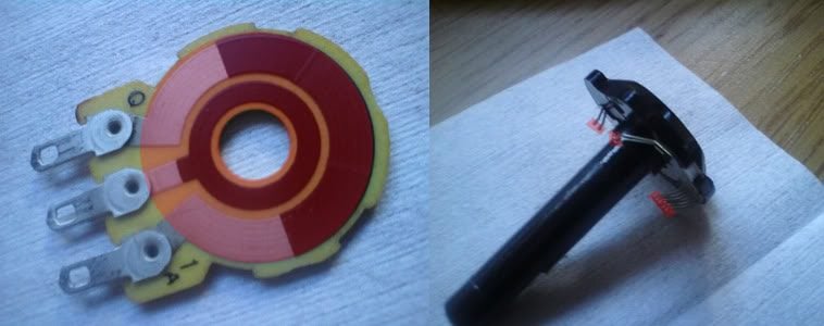
Then there was another POT with a Square Looking Pot track (had one but didnt know what to use it for) just trying to track it down again to look at it again
----Tracked them down the EXTRA LUG is a TAP at the MID WAY point
Without being able to Make a NEW Resistor Track, I'm with...
Two Resistor wafers Tapped in the middle, Common (Lug2) as Output, Tap as Input (Lug4)
Cross Over Wafer, Lug1 PickUpA, Lug2 Ouput & Lug3 PickUpB
As best as i can think at the moment on how to get a Blend POT
>Problems putting a Quad Pot back together with a Pin to hold it in place, so much easier on a Push/Pull Switch<
|
|
|
|
Post by Yogi B on Aug 16, 2019 3:18:19 GMT -5
@angelsbunny or, erm make that @angeisbunny, your plan to fabricate a PCB replacement of the conductive element reminded me of something I came across a while back: 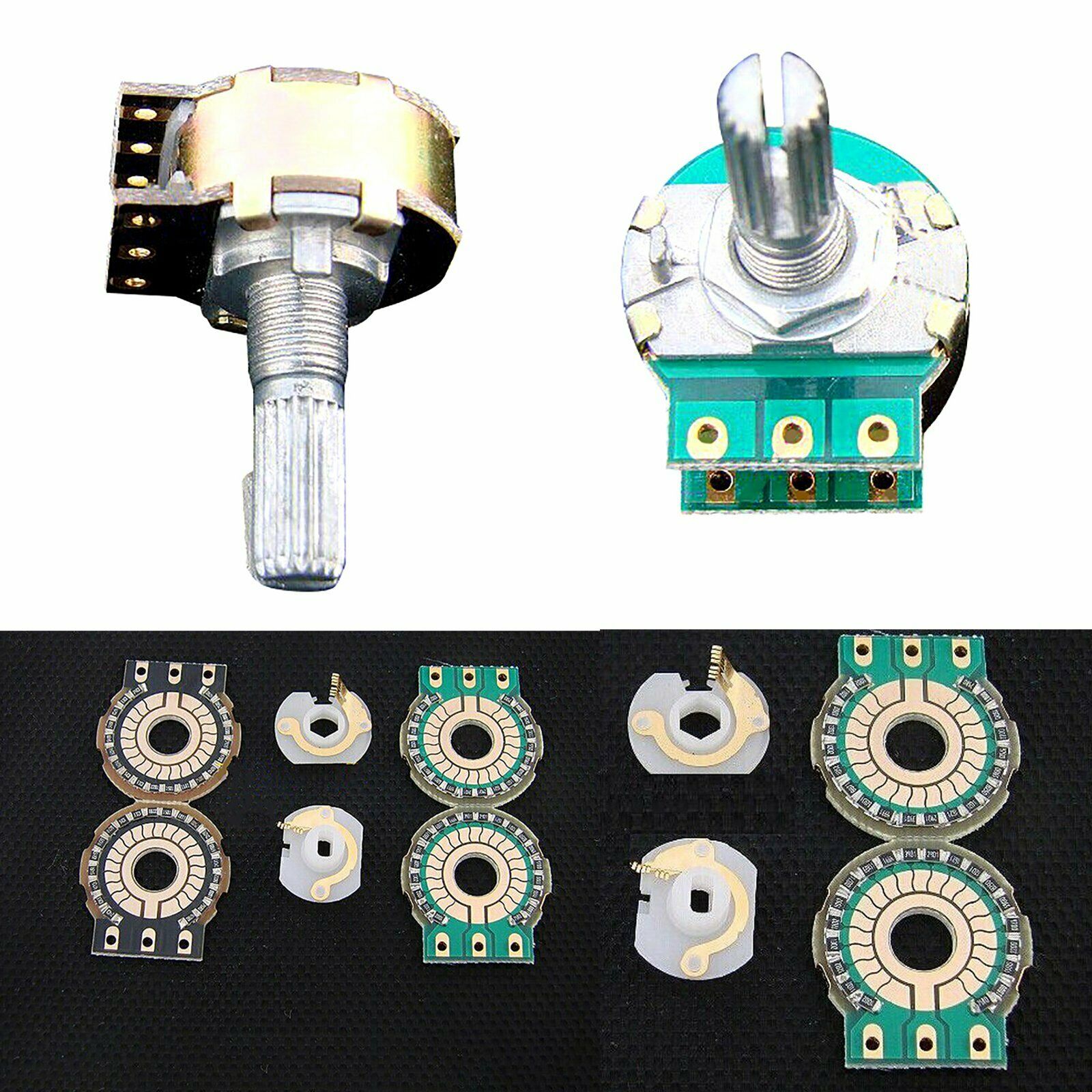
Which are knock-offs of DACT's stepped SMD attenuators, yet made even more compact and thus seemingly a great, much more appropriately sized, alternative to the large rotary switch + through-hole resistor networks that I've seen previously. With there intended use as a stereo attenuator the two resistor layouts are mirrors of each other, such that externally they both represent a log taper. Below is a table I found for a 100k version, it lists the decibel attenuation (if used as such), cumulative resistance (between terminals 1&2), and finally the values of the individual resistors. Also, take note that the default taper is much more extreme, at approx. 1%, than the 10% commonly used in guitars -- however unlike a carbon track there is much more potential of either modding it to suit or making your own from scratch, as long as you have the necessary soldering skills. 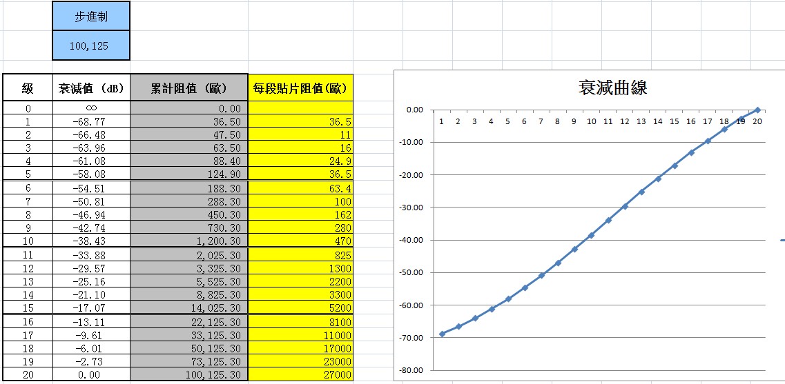
Despite what the above graph might imply, being stepped these obviously won't give a perfectly smooth response, but I have to wonder exactly how noticeable that is in actuality. Anyway, food for thought. |
|
Deleted
Deleted Member
Posts: 0
Likes:
|
Post by Deleted on Aug 16, 2019 15:32:49 GMT -5
i like the look of these and did think about it, but i such at SMD  Three i'd been working on some times RED: Vampire is a Bleed circuit that drops the capacitor as it is turned down 1040pF .. 630pF .. then 220pF YELLOW: 1P6T switch, was to work on a BASS guitar GREEN: 1P2T (mm the text says 2P2T!!) but is a strange one Y,YZ,ZX and X |
|
felixq78
Rookie Solder Flinger

Posts: 2
Likes: 0
|
Post by felixq78 on Dec 18, 2020 8:05:19 GMT -5
No one ever speaks about that pot under the bridge cover on the Aria Lapsteel. Finally someone who knows speaks about it. Thanks.
|
|