|
|
Post by perfboardpatcher on Feb 20, 2016 4:19:30 GMT -5
ReTrEaD, The spec sheet could have stated "internal DC resistance" and "external impedance". Ideally the external impedance (of the load) should be as ohmic (600 ohms,+/- 10%) as possible to get the most power across a wide frequency range. I'm not in favor of considering an electric component as a black box. In some way external impedance and internal impedance (transformer coil) must correlate. Is there a thumb of rule, like for example, the external impedance corresponds with the reactance of the coil at a certain frequency if even only for this particular size of transformer and brand? I understand it's not the 1kHz, that was just the frequency Xicon used for testing. 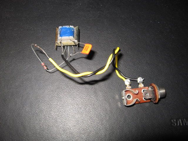 To add some more confusion I did some measurements on a transformer used as inductor. As you can see in the picture the transformer is about the size of the Xicon ones. The actors starring in the picture are: a no-name transformer with primary resistance 1k, a 3n3 cap and a 22k resistor constituting a series notch filter. I used a signal generator and a oscilloscope to determine the notch frequency and to measure (peak) voltages. The smallest signal for my 10:1 probe is 25mV. I adjusted frequency and level on my signal generator and obtained a minimum of 25mV across my notch filter at a frequency of 1.1 kHz. Calculation gave me a self inductance L = 5.7 Henry. But when I checked the signal level it wasn't what I expected. 25mV across the notch filter, 87.5mV input level. Which means the attenuation is 3.5 times and not (22000+1000)/1000. BTW the voltage across the transformer coil is 95mV. I repeated the measurements at different signal levels: minimum 100mV input level 220mV attenuation 2.2 times voltage across transformer coil 290mV minimum 500mV input level 950mV attenuation 1.9 times voltage across transformer coil 1.02V The 500mV minimum was found at a frequency of 800Hz. I raised the signal levels a bit further but the notch frequency didn't drop lower. I don't have Xicon transformers so the task of putting those under test I leave up to someone else. Cheers, Paul |
|
|
|
Post by reTrEaD on Feb 20, 2016 10:02:28 GMT -5
Ideally the external impedance (of the load) should be as ohmic (600 ohms,+/- 10%) as possible to get the most power across a wide frequency range. Wait, what? Are you suggesting that 600 ohm is some sort of magic impedance? I assure you it is not. While it's true that quite a bit of audio gear is designed around a 600 ohm impedance, there isn't anything particularly special about that. Thinking that these transformers have any relationship to that is just plain wrong. I'm not either. And component manufacturers aren't. They give you the pertinent information to use their components as they were intended to be used. When used as a transformer, refer to my previous post. When using a single winding simply for its inductance value, you're on your own. No such rule of thumb exists. The impedances quoted for these transformers are only valid for the transfer function when used as transformers. Again, this is about transfer function into the specified load (which varies for each transformer listed), it's not about inductive reactance. This is fairly useful. One thing to be aware of is core saturation. Overdriving can skew the results. Stray capacitance (oscilloscope probe, etc) might be a factor if the known capacitor is very small. Of course the tolerance of the known capacitor is also an issue. But in general this is a decent method to get in the ballpark when determining the value of an unknown inductor. Configure the inductor and capacitor in series and adjust the frequency until you find the dip. Or configure them in parallel and look for the peak. I wouldn't be terribly concerned about that. If one wanted to go through some very complicated trig or plot the vectors (resistance horizontal, capacitive reactance and inductive reactance vertical, in opposite directions) they could reconsile the fact that the voltages seem to be larger than expected (due to phase angle differences). But why bother? What we're after here is determining the approximate value of the unknown inductor. With a dip at 1100Hz and a capacitor of 3.3nF, I calculate 6.3H. Not sure why that differs from your calculation, but it seems inconsequential anyway. Roughly 6H. Good enough for government work. You outlined the procedure, so that's worth plenty to anyone interested in doing the work.  |
|
|
|
Post by reTrEaD on Feb 20, 2016 10:07:23 GMT -5
sumgai: "Unklmickey" "ChrisK"
High praise is.
Having my name mentioned in the same post as a couple of GuitarNutz legends has me blushing.
|
|
|
|
Post by perfboardpatcher on Feb 20, 2016 15:30:58 GMT -5
I keep it short without the quotes, ReTrEaD
Not a magical number, but 600 ohms because I thought we were discussing the 42TL021-RC in particular.
Yeah, I can be pretty stubborn. If only someone could provide me a bunch of measuring results concerning self inductance for the 42TL series transformers I could do the calculations to find some correlation myself. I want to believe you, ReTrEaD, but falsification works better for me.
Actually the 3.3nF capacitor measured 3.4nF and I was "guessing" my way in the formula towards 1100. I got it close enough for rock 'n roll.
I'm not so concerned about 5.7 vs 6.3. Actually I'm more concerned about JohnH' GuitarFreak plots for 15H and 1.5H inductors.
Paul
|
|
|
|
Post by reTrEaD on Feb 20, 2016 16:18:10 GMT -5
What is it specifically that bothers you about the GuitarFreak plots?
The notches are where one would expect for those values (roughly 600Hz). The overall response curves aren't flat on pickups due to their internal internal inductance, resistance, and capacitance. And the effect of typical cable capacitance. (refer to the dark blue line in the plot he posted on Feb 15)
The interaction outside the notch region isn't unexpected with a complex source impedance. For instance the severe attenuation of the higher frequencies with the necessarily larger capacitor when using a smaller inductor. And the shifting of the pickup resonance peak. And in general, a lower inductive reactance and lower capacitive reactance in the notch filter will naturally result in a lower shunt impedance, even at at resonance.
|
|
|
|
Post by JohnH on Feb 20, 2016 19:56:13 GMT -5
I had a post typed out, then noticed it had all been said above.
Anyway, the notch frequencies on the GF plots correspond closely to the classic f = 1/(2Pi((LC)^0.5)) formula, at which inductive reactance is equal and opposite to capacitive reactance. Outside of that null, the full system needs to be considered since its all interactive, which is what you see (so far as we can represent it) in the model results.
On getting Inductor values, its worth noting that for about $50, you can now buy a yellow multimeter that will measure Inductance directly, up to 20H. I have one, and from tests on a few pickups where I know the spec, it is accurate enough for what we need. This opens up a rich un-tapped vein of redundant wall warts, power-bricks and other obsolete kit, from which wound components such as transformers can be salvaged and tested for our purposes.
|
|
|
|
Post by perfboardpatcher on Feb 21, 2016 3:48:39 GMT -5
JohnH, As I've demonstrated my calculated null - going strictly by electrical properties - doesn't reflect reality. At least you could acknowledge that I contributed something to the forum.  Yep, that's the formula I used. On my Casio, substituting L until I got close to 1100. Not close enough for everybody.  cheers, Paul |
|
|
|
Post by perfboardpatcher on Feb 21, 2016 9:30:20 GMT -5
Guys, this is from our very own forum. Good job DuckDuckGo.
Paul
|
|
|
|
Post by reTrEaD on Feb 22, 2016 10:31:24 GMT -5
Confirmation is. That's a quote from ChrisK's post in the "Inductors, Varitones, etc..." thread. If I'm channeling anyone, it must be Unklmickey, not ChrisK. I'll submit two interesting observations to anyone who's interested. These transformers from Xicon seem to be using the same core. All other things being equal, the inductance of a coil increases by the square of the number of turns. (1)The following transformers have the same primary impedance (10k) listed in their specs: 42TL012-RC 42TL024-RC 42TL002-RC 42TL019-RC 42TL218-RC But the number of (primary) turns is different on each these, ranging from 1840 (42TL218-RC) to 2500 (42TL012-RC) www.mouser.com/ds/2/449/XC-600127-202003.pdf(2)42TL012-RC 10k 2500turns 42TL006-RC 20k 2700turns 42TL025-RC 17k 2800turns |
|
|
|
Post by perfboardpatcher on Feb 24, 2016 13:42:50 GMT -5
Could it be as simple as taking the 42TL 021-RC as reference and calculate the self inductances of other transformer primary coils on basis of turns ratio? Example -> 42TL019-RC, L =(2000/1320)^2 * 1.5 = 3.44 H (If the self inductance of the primary coil of the 42TL021-RC is 1.5H and if we're dealing in all cases with one and the same type of transformer core.) There's no relation between primary impedance and self inductance as the last column shows. 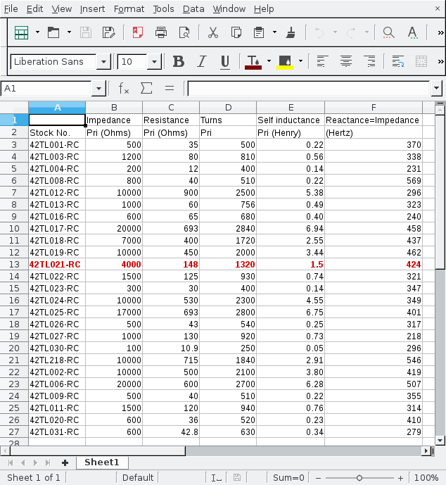 Paul |
|
|
|
Post by JohnH on Feb 24, 2016 16:20:07 GMT -5
ReTrEaD points out that Inductance is related to the square of the turns ratio, rather than just linearly. But that is 'all other things being equal', which they aren't.
I have seen online calculators for working out inductance from windings, coil dimensions and core properties. They might give some insight. (Googleable)
|
|
|
|
Post by reTrEaD on Feb 24, 2016 22:59:26 GMT -5
But that is 'all other things being equal', which they aren't.
Indeed!
I can't say exactly what happens with an iron core inductor but with an air core, the inductance increases by the square of the diameter. With a layered winding, the later windings will provide significantly more inductance per turn than the earlier windings.
Making the bold assumption that the primary is wound first and secondary on top of that, in cases where the secondary takes up a lot of the outer real estate, the primary would necessarily be smaller in diameter and wound with thin wire to accomplish this. Same number of turns might result in significantly different primary inductance.
|
|
|
|
Post by perfboardpatcher on Feb 25, 2016 14:04:56 GMT -5
If I would make predictions based on L=5.7H, C=3n4F, R(l)=1k I would get this: 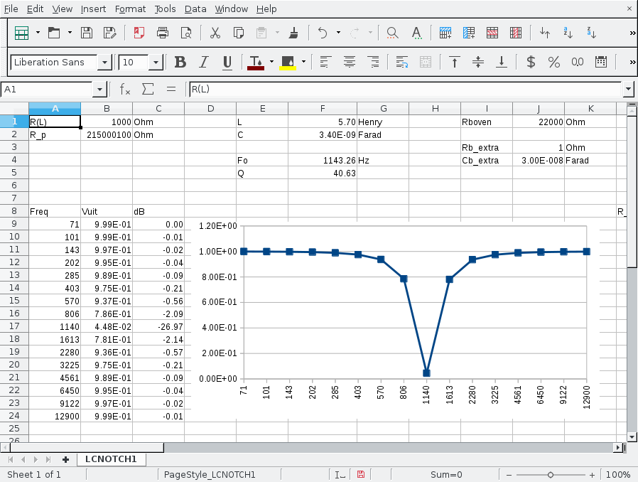 But what I measure looks more like this: 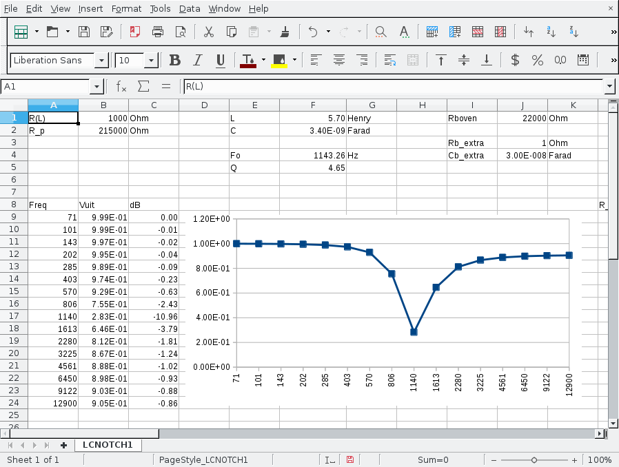 R_p : Resistor in parallel with primary coil of transformer. |
|
YouXE
Rookie Solder Flinger

Posts: 5
Likes: 0
|
Post by YouXE on Apr 6, 2016 16:30:06 GMT -5
I hope I can shed some light in that issue about the value of some Xicon transformers. I bought two 42TL017. In addition, I have three 42TL021. To measure them I also bought a L/C meter: LC-100A. Not the most accurate in the market, but it is ok. 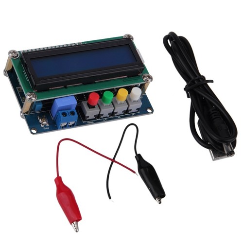 Well, these are the (approx.) inductance values I get: - 42TL017: Primary 10.40H-10.96H - 42TL021: Primary 2.140H-2.191H-2.354H Sooner or later I will make a passive vari-tone with the 42TL017 for my bass guitar and a video demostrating the results. I will keep you informed! |
|
|
|
Post by perfboardpatcher on Apr 7, 2016 14:18:13 GMT -5
Well, these are the (approx.) inductance values I get: - 42TL017: Primary 10.40H-10.96H - 42TL021: Primary 2.140H-2.191H-2.354H Sooner or later I will make a passive vari-tone with the 42TL017 for my bass guitar and a video demostrating the results. I will keep you informed! This is useful information, YouXE! |
|
|
|
Post by wolf on Oct 8, 2016 23:31:25 GMT -5
Well, I figured after a year and a half I should post an updated graphic of the Gibson Varitone.
One thing unusual you might notice is that I drew a wire on top of the resistors.
Every diagram I have seen is pretty unclear and I wanted to make a diagram that shows the circuit more clearly.
Let me know if there are any mistakes.
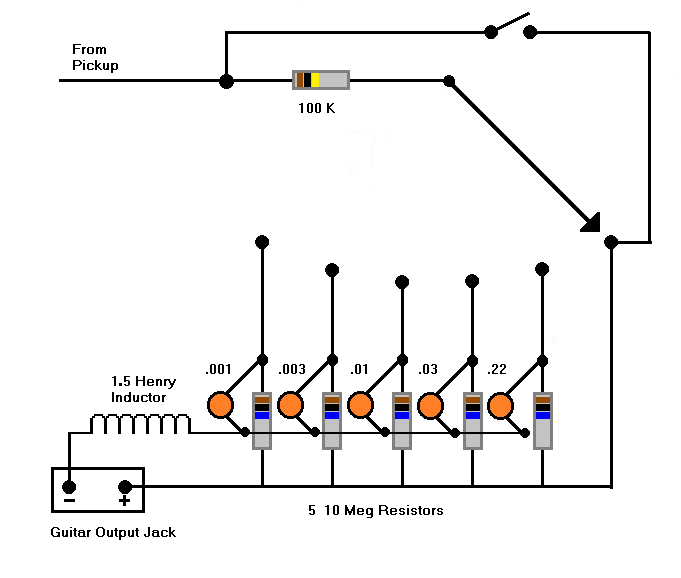
|
|
|
|
Post by reTrEaD on Oct 9, 2016 21:51:05 GMT -5
Let me know if there are any mistakes. Hello my lupine friend. I hope all is well at the cubic dozen. The diagram looks very close. Seems to have all the same connections as the original except that you've added a SPDT switch that isn't necessary if the pole of the SP6T is connected to the output rather than the 100k resistor. |
|
|
|
Post by wolf on Oct 11, 2016 12:30:47 GMT -5
reTrEaD Thanks for looking at the graphic.
The reason I added the bypass switch is to have an actual bypass of the entire circuit.
It is so much easier just to throw a switch instead of going from position 5 to position 1 on a rotary switch.
|
|
|
|
Post by wolf on Oct 12, 2016 18:47:13 GMT -5
Well, I have been thinking about this a little bit more and came up with another graphic.
I decided to put the circuit into a stomp box and also decided to put in another capacitor/resistor pair (.1 mfd).
For the mathematically minded amongst you, the capacitor values appeared to increase by a factor of the square root of 10 (about 3.16).
That being the case, the jump from .03 to .22 seemed a bit drastic (7.33) and so the .1 mfd capacitor was added.
Of course, to continue that mathematical pattern, the capacitor after that should be .3 and not .22.
Did I think about this way too much?
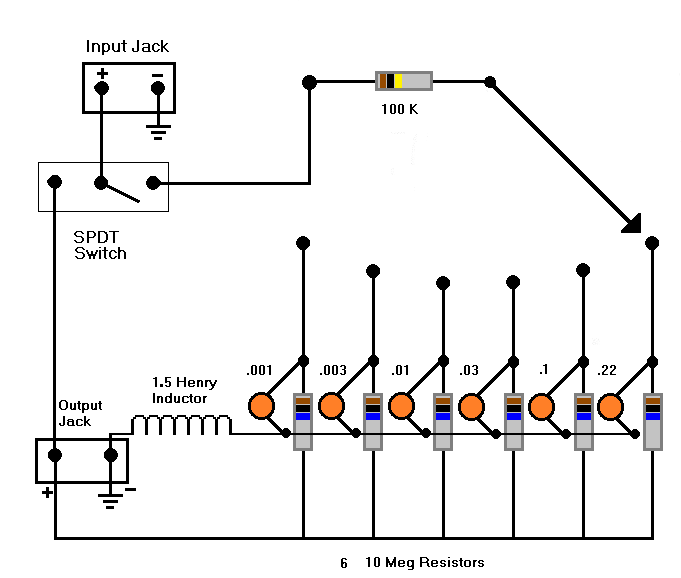
|
|
|
|
Post by sumgai on Oct 12, 2016 20:28:45 GMT -5
Errrr.......
wolf, can I get some of what you've been smoking, please? 
Trace back from the output jack's positive terminal. The first thing that line sees is a bunch of resistors, right? And don't those resistors mate up to one capacitor each, eh? And where do all those caps go, do ya suppose?
Tha's right, they go through the inductor and thence onward to ground, all of them. Which then says that all 5 or 6 res/cap pairs are in parallel with each other, regardless of where the switch might lay. BTW, this is true for both diagrams, sorry to say. Even the so-called bypass won't have any effect on the signal, the end result will sound the same, or nearly so, no matter what switch position you might choose.
And for the record, my EE brain says that the amount of signal coming out of a pickup and going through a 10Meg resistor is probably gonna need a bit of a boost, in order to be useful. In a stompbox arrangement, the incoming signal level might well be high enough to not need additional boosting before the next stage.
I think the best thing I can say right now would be "back to the drawing board for you". 
HTH
sumgai
|
|
|
|
Post by reTrEaD on Oct 12, 2016 23:26:38 GMT -5
Yeah, pretty much. So we have about 1-1/2 to 2 Meg of resistance in parallel with the signal. Small potatoes, really. I'd be more concerned about having twice the cable capacitance because you have two cables (one from the guitar to the passive stompbox and one from the stompbox to the amp) than would be about the parallel resistance.
Never hurts to have a buffer (not necessarily gain) but I think you're making the proverbial mountain out of a molehill.
|
|
|
|
Post by wolf on Oct 13, 2016 1:25:01 GMT -5
I drew the graphic based on this schematic:
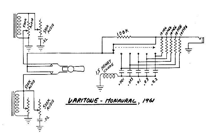 "] "]
So, sumgai is there a problem with this circuit too, or did I just make a mistake in my graphic?
|
|
|
|
Post by sumgai on Oct 13, 2016 12:12:04 GMT -5
wolf,
Since reTrEaD appears to be poopoo-ing my concerns, to some degree at least, I decided to go back and do some quick research. I have to "eat some crow", as your diagram is almost a verbatim copy of Gibson's classic circuit, value for value and connecting point for connecting point. It would appear to me now, that Gibson themselves didn't think this thing through, but then again, for that (in)famous scroll at the top of the peghead, they didn't have to, now did they.
All of which means that there are still problems with effect on the signal, even when trying to bypass the thing. I suggest you go back and read the PDF file I referenced in my first post in this very thread. A complete discussion of what I'm talking about is contained therein, and I think that author expresses my concerns much more succinctly than I ever could.
I was never a fan of mid-scooping like this, but at one time I did design and implement (for others) a better circuit that didn't exhibit these problems. (And I'm almighty sure that I wasn't the first one to do so.) The clue lays in what retread said: the 10Meg resistors themselves don't present much of a problem - he's both right and wrong about that, depending on what one is looking at, at the moment. Let's see where you go next, in your quest to build not only a useful circuit, but one that does indeed overcome the problem we'll call "The Bypass Quandry". 
HTH
sumgai
|
|
|
|
Post by wolf on Oct 13, 2016 22:47:57 GMT -5
Okay I redrew it sans resistors.
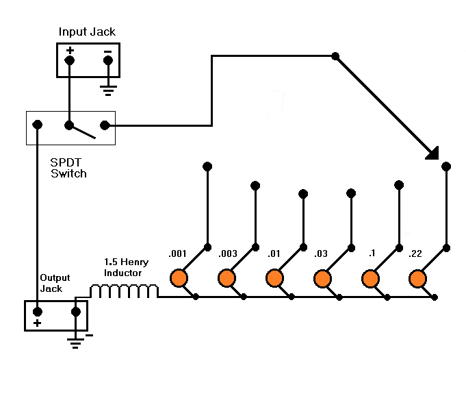
|
|
|
|
Post by sumgai on Oct 14, 2016 14:03:07 GMT -5
wolf,
As I've said before, it's always a good idea to start with the bare minimum, and once that's been tested to satisfaction, then add on to it as needed.
Now, if John or some other kind soul will xSPICE this thing, we'll see if we might need to add anything, or if the results will be satisfactory as is. I suspect that the tone will come out the same, your version compared to Gibson's version, or pretty darn close. I'm not too sure just why those 10meg resistors are there, but they shouldn't be for 'snubbing' any popping (from switching caps), as that's normally done to ground, not the hot signal lead.
(Personally, I like the idea of a separate bypass switch, in that I think like you do - temporarily go from some selected "Tone" to none at all, and back to the same one again at the flick of a switch. When playing in the middle of a tune, it's always easier to hit the extreme position(s) of a switch, instead of somewhere in the middle of a multi-position unit.)
HTH
sumgai
|
|
|
|
Post by reTrEaD on Oct 14, 2016 17:43:20 GMT -5
I suppose one could do that. But rather than dragging the cart on skids and finding out that I need to re-invent the wheel, I'd rather analyze at what others have done before me and learn from their experience. xSpice, pSpice, or Parsley, Sage, Rosemary and Thyme won't tell you what you need to know about the 10Meg resistors. It will probably show their overall effect to be for all intents and purposes, statistically insignificant. But it won't show the transients that can occur when changing the position of the rotary switch if they aren't there. Actually, the transient suppression will be slightly superior if the 10Megs are connected to the signal rather than ground.  |
|
|
|
Post by JohnH on Oct 14, 2016 18:53:49 GMT -5
We got into working out some Varitone circuits o this thread recently, with analysis: guitarnuts2.proboards.com/thread/7568/nighthawk-hsh-redux?page=2Wolf - if you have built the Gibson circuit, what do you think of the variations and the extent of tone notching? I've never built one, but when analysing them, I always reckon a bigger inductor than 1.5H is better. The link above is based on 3H. On the 10M resistors, anti pop, but also they are going to eat a little into the treble. Probably one of them is not significant on its own, but 5 togther is 2M extra load, and that will carve a db or two off the treble. If I had one, Id work out the cap values I wanted, then re-calculate them as a series chain of caps, which can then be all drained at once with a single 10M resistor, if pops are found to be significant. |
|
|
|
Post by sumgai on Oct 14, 2016 23:33:23 GMT -5
John,
Your series chain idea for the caps was exactly what I had done, Lo These Many Years Ago.
As to the loading effect of 5 (or 6) 10meg resistors, recall that they will each go through a capacitor in order to get to ground. This is where reTrEaD gets away with the statement that their combined effect will be minimal - just like a tone control when all the way up to 10 has little to no noticible effect on the output's tone. So instead of just "knocking off a bit of the highs", it's a complex calculation. And that's before we begin to factor in the shorting of a selected resistor, thus coupling a cap-and-coil series pair straight to the hot signal wire. At that point, there's a whole lot of action and interaction going on, no? 
reTrEaD,
I think this is one area where we're gonna have to disagree, vis-a-vis the snubbing effect of "to hot" versus "to ground". In general, one should not impose a spike onto the hot signal line. There are time when it may be unavoidable, but for the most part.....
I wonder how much any popping might be reduced by that 100K resistor. In this instance, it is a snubber, or more correctly, an in-rush current limiter device.
As for building on the ideas of forerunners, I'll just counter with, how many over-engineered circuits have you seen, that really should have been made much more simple, before going into production? If the answer is more than Zero, then you know what I mean by advocating for starting out with the basic circuit first. 
|
|
|
|
Post by reTrEaD on Oct 15, 2016 7:42:47 GMT -5
Disagree all you like. The truth of the matter is, referencing the 10Meg resistors to the signal will cause the unused capacitors to be slightly closer to the signal than ground. I agree completely. At the moment in time when one of the capacitors is disconnected from the signal line, there may be a charge across the capacitor. This is not a problem at all because at that precise moment the top of the capacitor and the signal are at the same potential. And the 10Meg resistor causes it to follow very loosely with the signal. Without the resistor, the charge remains trapped on the capacitor. When that capacitor is reconnected to the signal, that's where the problem occurs. They also go through an inductor, in series with the capacitors. But the reactance of the capacitors and inductor is far smaller than the 10Meg resistors. So for all intents and purposes we can look at just the effect of the 10Meg resistors in parallel with each other. The 100k resistor makes life worse, not better, in regards to capacitor switching transients. It's not a "snubber". John correctly identified its function as being "the top half of a voltage divider", in a post in the middle of the first page of this thread. (the post that includes the original Gibson drawing) Any transient we create by connecting a capacitor with a trapped charge will see a higher resistance in series with the input source, so its effect will be stronger on the output. Bad juju. If I had one, Id work out the cap values I wanted, then re-calculate them as a series chain of caps, which can then be all drained at once with a single 10M resistor, if pops are found to be significant. John, I believe the series chain is an inherently good idea. However I would recommend a 10Meg resistor across each individual capacitor. When you fold a series chain of capacitors upon itself, the net voltage becomes zero but the voltage across any individual capacitor is indeterminate. You could find yourself with an "equal but opposite" situation of trapped charges. And since the resistors would essentially be in series when the full chain is used, the loading effect of the resistors would never be less than 10Meg. In most cases, greater than. |
|
bassxtreme
Rookie Solder Flinger

Posts: 16
Likes: 0
|
Post by bassxtreme on Dec 30, 2016 3:35:49 GMT -5
so which Xicon transformer is near 15H? Will the 42TM117 do it?
|
|