|
|
Post by Carlos Sanz on Jul 21, 2018 8:00:41 GMT -5
Well, this thread is a little old, but just in case someone comes back to it, let me add some data: The Chris Wargo’s article provided by Sumgai at post #3 is quite interesting. But the analysis is not taking into account that after the varitone, the input impedance of the amplifier can be something about 1 Mega-Ohm. If the bypassed varitone equals about 2 Mega-ohms, its effect can be (at least) measurable. I’m starting with LTSpice and I’ve made a couple of simulations. This is the circuit I’ve simulated, with a Humbucker (consisting of two single Coil in series; I think the simulation would be more precise this way), a 500K/47n Tone control and a 500K Volume Control (both fully open). The cable capacitance is set to 1nF and the amplifier input impedance is 1 Meg-Ohm:  The frequency response of the bypassed Varitone compared with the same circuit without varitone is in this graphic. There is about 0.5 dB of difference in the peak resonance: 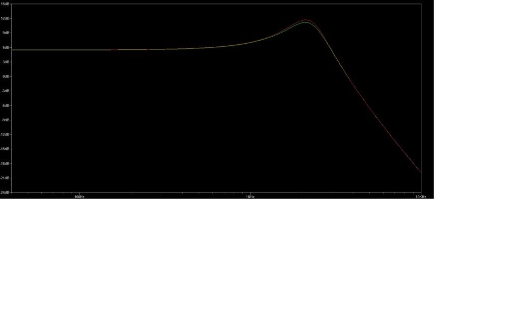 For sure I wouldn’t be able to tell one sound from the other, but I would never state that a musician couldn’t. Furthermore, the inductor is problematic in simulations. Inductors are always far from ideal and who knows what the inductor can do at high frequencies. For my next holidays, I’ll try to build a varitone with a true-bypass position and I’ll try to measure its real response. I’ll let you know if I finally coudn't. I think that a true bypass could be designed easily. Since most 6-position rotary switches out there have 2 poles, I think one of them could be used to disconnect the Varitone circuitry completely. It would look like this: 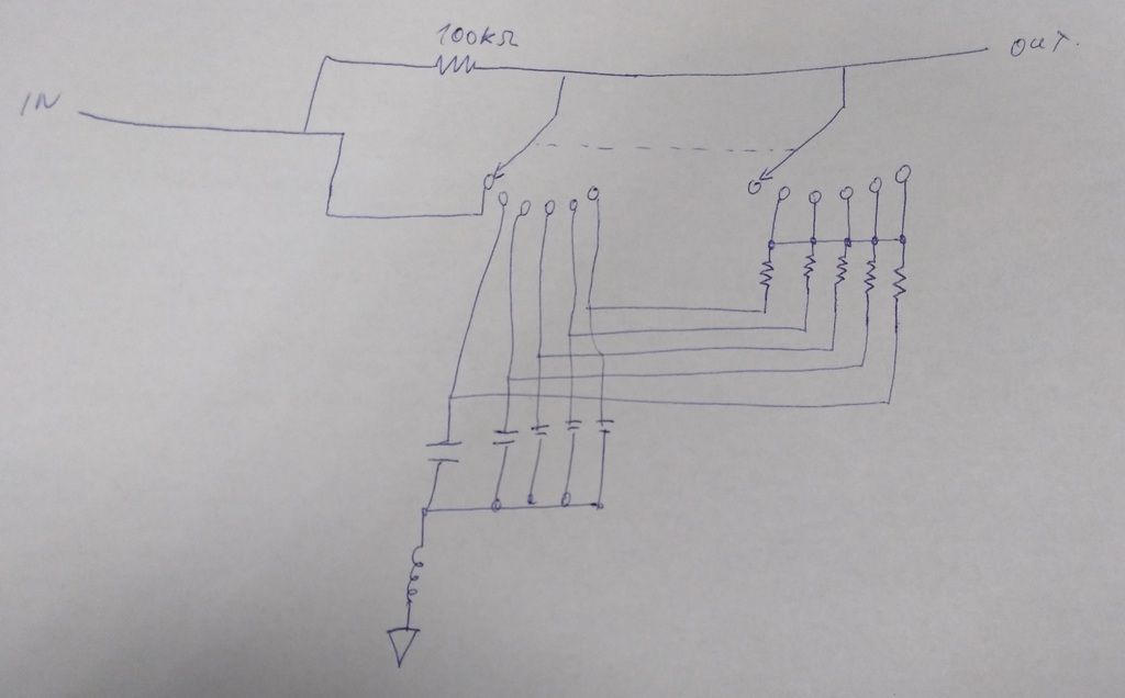 BTW, do you recommend me Make-before-brake or Break-before-make for this? I’ve already bought one of each kind at Mouser, along with a Xicon 42TL019 Transformer. It happens that I’ve been able to use an impedance meter and I’m quite confused. The meter I had provided 3 frequencies for measurement: At 100 Hz, the primary measured 5.5 Henries At 1000Hz, the primary measured 3 Henries At 10000Hz, the primary meter said it was not an inductor anymore but a capacitor. It seems that internal stray capacitances are more important than self-inductance at moderately high frequencies. Two conclusions arise from this: - Assuming that the meter used by YouXE reported in post #43 is working at low frequencies, there seems to be a direct ratio between the stated input impedance and the inductance value in the Xicon 42TL family: · 42TL017 primary impedance=20K, inductance=10 Henries · 42TL019 primary impedance=10K, inductance=5 Henries · 42TL021 primary impedance=5K, inductance= 2.5 Henries - Probably the small audio transformers used as inductors are not as faithful to the original Gibson Varitone sound as the inductors they used in the 60’s. An inductor is more than just a value and probably the side effects of original inductors were quite different than small inductors. And that’s it by now, I think. I’ll try to confirm theory with some practice this summer. |
|
|
|
Post by reTrEaD on Jul 21, 2018 10:45:44 GMT -5
BTW, do you recommend me Make-before-brake or Break-before-make for this? In my estimation, the Make-before-break will be a better choice. There will always be some possibility of clicking due to the caps being suddenly connected. But retaining connection to a cap already in the circuit while the next one is being connected will mitigate that to a small degree. |
|
|
|
Post by Carlos Sanz on Jul 23, 2018 8:30:46 GMT -5
Thank you, reTrEaD.
I think I'll try a true-bypass pedal version of this circuit when I finish my actual Strat project.
I'll be back to let you know how it goes!
|
|
|
|
Post by zedsnotdead on Oct 23, 2020 4:50:31 GMT -5
Sorry to resurrect such an old thread. So I bought a varitone kit from a fleabay seller. I solder the components as per the given instructions document. At the end it look like this: 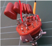 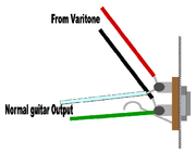 So I did a schematic of it, and also re-drawn the physical connections for a future PCB. 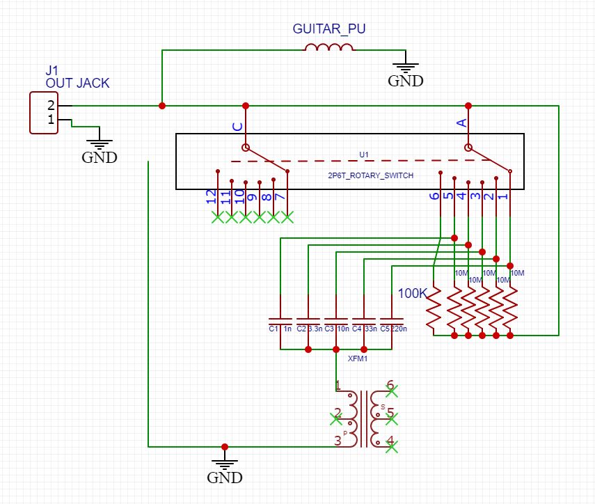 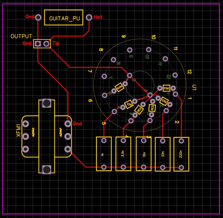 Now, given the original schematic from Gibson, this doesn't match up! I mean, look at the 100K resistor connection. 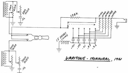 I mean, shouldn't this 100K resistor be connected between both common lugs in the rotary switch??? I tried it and it works! But HOW? What am I missing here??? Thank you for your help! |
|
|
|
Post by reTrEaD on Oct 23, 2020 10:05:53 GMT -5
Hi zedsnotdead.  to Guitarnuts2. Yes, the varitone is incorrectly connected. Yes, it will still function when connected that way but the effect won't be as strong. No, the 100k should not be moved. Instead the 'From Guitar' should connect to lug 6 and nowhere else. That way in the 6 position, the switch makes a direct connection between 'From Guitar' and the output jack. In all other positions, the signal goes through the 100k before connecting to the varitone and the output jack. Can you see how that would make a bit of difference? |
|
|
|
Post by frets on Oct 23, 2020 14:32:32 GMT -5
Hi guys, Not to confuse the subject, I had this diagram in my files that I thought might help.👻🎃👻🎃 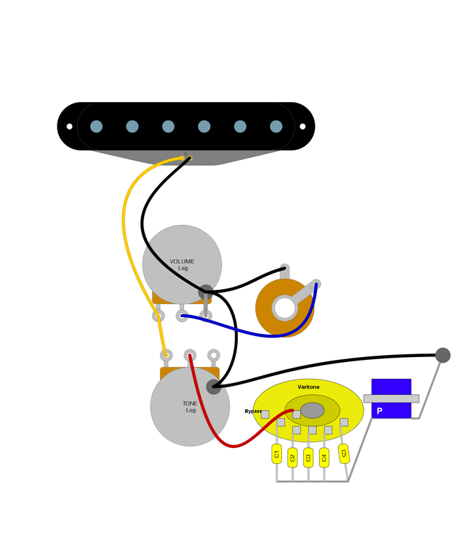 |
|
|
|
Post by zedsnotdead on Oct 23, 2020 19:32:58 GMT -5
Hi guys, Not to confuse the subject, I had this diagram in my files that I thought might help.👻🎃👻🎃 This will come handy!! Thank you!!  |
|
|
|
Post by zedsnotdead on Oct 23, 2020 19:34:35 GMT -5
Hi zedsnotdead.  to Guitarnuts2. Yes, the varitone is incorrectly connected. Yes, it will still function when connected that way but the effect won't be as strong. No, the 100k should not be moved. Instead the 'From Guitar' should connect to lug 6 and nowhere else. That way in the 6 position, the switch makes a direct connection between 'From Guitar' and the output jack. In all other positions, the signal goes through the 100k before connecting to the varitone and the output jack. Can you see how that would make a bit of difference? Yes I do indeed. Thank you so much! Time to get the soldering iron out and do some tests. I'm trying to create a circuit that would be a combination of a varitone+red llama overdrive in a pedal format. But first I need this varitone to act straight  |
|
syddd
Meter Reader 1st Class
  
Posts: 62 
Likes: 10
|
Post by syddd on Nov 26, 2020 8:19:04 GMT -5
Is it worth the hassle of finding a 15H choke for varitones? Or is merely finding the right notch frequency and identifying the right capacitor going to yield similar results?
From looking at the above posts...42TL017 will get me in the ballpark?
|
|
|
|
Post by frets on Nov 26, 2020 10:02:02 GMT -5
Hi Sydd, Although back in the day Gibson Varitones had ginormous Henrie values for the transformer component, today the recommended values are somewhere between 1.5H - 2.6H. These would be 42TL021 4K Ohms 1.5 Henries or 42TL018 7K Ohms 2.6 Henries. I build a lot of Varitones and will tell you anything close to 42TL017 20K Ohms 7.5 Henries is a bit much. At least for me, the notching of the relationship of the caps:inductor (transformer) is 1.5H. And that’s what I use each time I construct a Varitone. Of course, I encourage you to experiment with various values given it’s a matter of personal taste. The most common means of induction via the audio signal transformers you’re referencing; i.e., Xicon Audio Signal Transformers are available through Mouser Electronics. You may find that you prefer 1H up to 3.75H. However, if you want to be absolutely traditional with regard to the early Gibson models, 7.5H will be somewhat representative. I’ve tried a 10H and thought it sounded horrible. Then again, it’s a matter of personal taste. But keep in mind that Varitone making has been going on for a long time since the early days and 1.5H is the most recommended value. 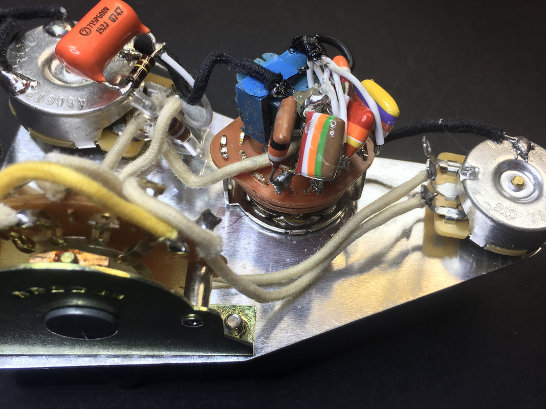 |
|
syddd
Meter Reader 1st Class
  
Posts: 62 
Likes: 10
|
Post by syddd on Nov 26, 2020 21:48:41 GMT -5
Hi Sydd, Although back in the day Gibson Varitones had ginormous Henrie values for the transformer component, today the recommended values are somewhere between 1.5H - 2.6H. These would be 42TL021 4K Ohms 1.5 Henries or 42TL018 7K Ohms 2.6 Henries. I build a lot of Varitones and will tell you anything close to 42TL017 20K Ohms 7.5 Henries is a bit much. At least for me, the notching of the relationship of the caps:inductor (transformer) is 1.5H. And that’s what I use each time I construct a Varitone. Of course, I encourage you to experiment with various values given it’s a matter of personal taste. The most common means of induction via the audio signal transformers you’re referencing; i.e., Xicon Audio Signal Transformers are available through Mouser Electronics. You may find that you prefer 1H up to 3.75H. However, if you want to be absolutely traditional with regard to the early Gibson models, 7.5H will be somewhat representative. I’ve tried a 10H and thought it sounded horrible. Then again, it’s a matter of personal taste. But keep in mind that Varitone making has been going on for a long time since the early days and 1.5H is the most recommended value.  Thanks! I have a varitone in one of my guitars with 1.5H and 1nF - 220nF caps and was wondering if there was a better sound I could get. Would you recommend 1.5H for a bass inductor as well? Stellartone seem to talk up their 15H inductor on that basis. |
|
|
|
Post by frets on Nov 26, 2020 22:09:19 GMT -5
Sydd,
On a bass I never go higher than 3.75H (42TL019 10K Ohms 3.75 Henry). I’ve not heard of what the Stellartone 6 position bass Varitone uses, 15H just seems really high; but, again, experimentation will help. Also, It’s been my experience that transformers at 10-15H tend to be on the chunky side.😋
|
|
syddd
Meter Reader 1st Class
  
Posts: 62 
Likes: 10
|
Post by syddd on Nov 29, 2020 7:44:36 GMT -5
Sydd, On a bass I never go higher than 3.75H (42TL019 10K Ohms 3.75 Henry). I’ve not heard of what the Stellartone 6 position bass Varitone uses, 15H just seems really high; but, again, experimentation will help. Also, It’s been my experience that transformers at 10-15H tend to be on the chunky side.😋 Thanks! Out of curiosity, Whats the range of frequency notches you're using for the bass? Just for clarity, are you adjusting the capacitor values with the changing inductance? |
|
|
|
Post by frets on Nov 29, 2020 10:40:31 GMT -5
Sydd,
I go by what I think sounds good; as well as, what clients think sounds good. I’ve not done any testing as to the frequencies generated. Here’s what I use that I think sounds great and so do my customers.
Ingredients for a Great Sounding Bass Varitone
- 3.75H Audio Signal Transformer
- Alpha 6 position Rotary Switch
- 22nF, 33nF, 47nF, 56nf, 68nF, 82nF ( some guys like 100nF)
- Six 10 mohm resistors
You know how to make one so I won’t go into that. Like I said, I’ve tested many combinations and this is the one I use and that customers really like. But again, experimentation and listening I think is what is important. The actual sound produced at each position; whereby, one says, “That’s it, that sounds great.”
|
|
syddd
Meter Reader 1st Class
  
Posts: 62 
Likes: 10
|
Post by syddd on Nov 30, 2020 4:57:13 GMT -5
Many thanks Frets. I'll give it a go!
|
|
|
|
Post by frets on Nov 30, 2020 11:17:41 GMT -5
|
|
syddd
Meter Reader 1st Class
  
Posts: 62 
Likes: 10
|
Post by syddd on Dec 6, 2020 6:43:42 GMT -5
Thanks! Yes I am trying Mouser on backorder. I noticed you have six caps. Do you link it with a tone pot? or do you just have it always connected on one of the notches?
|
|
|
|
Post by frets on Dec 6, 2020 12:03:20 GMT -5
Hi Sydd, I take it that you saw my diagram several posts back on this thread. I believe that shows it connected to a tone pot. I use a two pole, six position Alpha Switch. www.mouser.com/Alpha-Taiwan/Electromechanical/Switches/Rotary-Switches/_/N-5g2i?P=1z0zlgnor www.ebay.com/itm/Alpha-6-Position-2-Pole-Rotary-Switch-Break-Before-Make/162516850535?hash=item25d6c25767:g:ncIAAOSwONBZGcM0You can connect the Varitone directly to the Volume. If so, the Varitone becomes the tone pot. You can also connect it to the tone pot. This allows one to roll in the values selected from the varitone. . And Sydd, I do usually only use 5 caps with the first position on the switch being a bypass. For guitar I do: Bypass, 10nF, 15nF, 22nF, 33nF, 47nF. For Bass: Bypass, 22nF, 33nF, 47nF, 68nF, 82nF (or 100nF ). |
|
|
|
Post by frets on Dec 6, 2020 15:30:27 GMT -5
Sydd, Here you go. This is how I make mine. They work great and have no switch popping. The Alpha 2 Pole 6 Position Rotary has the logo “Alpha” stamped on one side. This is the side you use. You count in from the top lug to the third lug to your right (looking down at the switch lugs). This is where the first cap/resistor combo go. You use the lug eyelet to thread one lead from the 22nF cap and one lead from the 10M resistor through the eyelet. Solder both leads in place. Move to lug #4 and do 33nF/Resistor. Continue on until you have the five lugs with Cap/Resistor Combos. Next snip all the soldered lead ends off leaving you one cap leg and one resistor lead per lug. Group only the the cap legs, twist them together and solder them together. Now, twist the Resistor leads together and solder them together. See where the hot pink hot wire that is soldered onto the inside switch lug? Take your soldered resistor leads and measure them up to that lug, be sure before you clip them that you can solder that grouped resistor lead to that same lug that the pink hot is on. Cut it back and solder it with the pink hot wire. Next, prepare your Xicon Audio Signal Transformer by looking at the “P” on front of it. Snip the middle lead off (the one between the first leg before the “P” and the 3rd leg after the “P.” This gives you two leads on that side. Snip the two leads off of the opposite side of the transformer. Now you take your grouped soldered cap legs and solder them to the Xicon Audio Signal Transformer’s first leg in front of the P. You then solder the leg after the P to a ground wire (Grey in the diagram) and solder that wire to ground (back of a pot). Make sure you don’t let the soldered cap legs touch the soldered resistor legs. I use clear nail polish and paint both sets of soldered legs to prevent grounding if the get smushed down). I also use the clear acrylic nail polish on the leads and clipped lead ends of the Xicon Transformer. Some folks use a 100k resistor on the line, I never do as I think it dulls the tone a bit. That’s it. 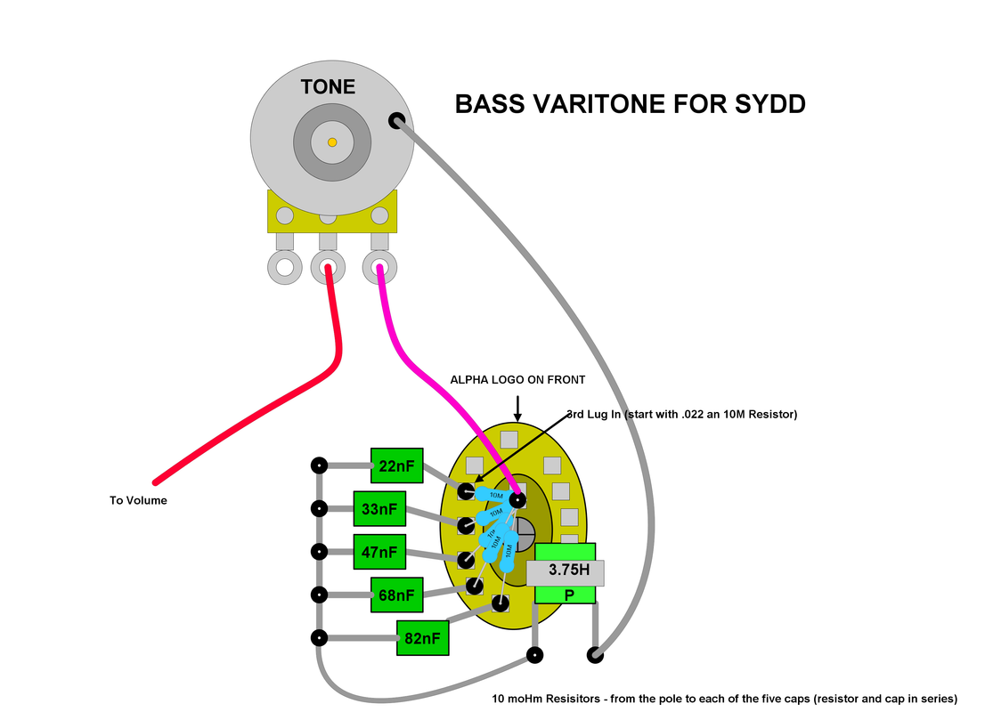 |
|
|
|
Post by unreg on Dec 8, 2020 21:00:41 GMT -5
frets, would clear acrylic nail polish be good to use to coat bare parts of wires? I haven’t been able to find my wire shields, so there’s a lot of bare parts of wire. Sorry, this is kind of off topic. 
|
|
|
|
Post by frets on Dec 9, 2020 12:44:13 GMT -5
Unreg,
For bare spots on wires, like plastic wiring, I use a small paintbrush or qtip and some Plastic Dip. You can get it at a hardware store and at most Walmart’s. It’s rubber. I’ve also used rubber cement. If the areas are small, clear acrylic nail polish would be just fine. But only after you’re finished with adjusting the wires. Nail polish is rigid once it sets.
|
|
|
|
Post by unreg on Dec 9, 2020 15:40:54 GMT -5
frets, thank you so much! 👍😀
|
|
syddd
Meter Reader 1st Class
  
Posts: 62 
Likes: 10
|
Post by syddd on Dec 28, 2020 21:24:03 GMT -5
Sydd, Here you go. This is how I make mine. They work great and have no switch popping. The Alpha 2 Pole 6 Position Rotary has the logo “Alpha” stamped on one side. This is the side you use. You count in from the top lug to the third lug to your right (looking down at the switch lugs). This is where the first cap/resistor combo go. You use the lug eyelet to thread one lead from the 22nF cap and one lead from the 10M resistor through the eyelet. Solder both leads in place. Move to lug #4 and do 33nF/Resistor. Continue on until you have the five lugs with Cap/Resistor Combos. Next snip all the soldered lead ends off leaving you one cap leg and one resistor lead per lug. Group only the the cap legs, twist them together and solder them together. Now, twist the Resistor leads together and solder them together. See where the hot pink hot wire that is soldered onto the inside switch lug? Take your soldered resistor leads and measure them up to that lug, be sure before you clip them that you can solder that grouped resistor lead to that same lug that the pink hot is on. Cut it back and solder it with the pink hot wire. Next, prepare your Xicon Audio Signal Transformer by looking at the “P” on front of it. Snip the middle lead off (the one between the first leg before the “P” and the 3rd leg after the “P.” This gives you two leads on that side. Snip the two leads off of the opposite side of the transformer. Now you take your grouped soldered cap legs and solder them to the Xicon Audio Signal Transformer’s first leg in front of the P. You then solder the leg after the P to a ground wire (Grey in the diagram) and solder that wire to ground (back of a pot). Make sure you don’t let the soldered cap legs touch the soldered resistor legs. I use clear nail polish and paint both sets of soldered legs to prevent grounding if the get smushed down). I also use the clear acrylic nail polish on the leads and clipped lead ends of the Xicon Transformer. Some folks use a 100k resistor on the line, I never do as I think it dulls the tone a bit. That’s it. Thanks frets. Will give it a go but I've just received the 42TL019-RC transformers and they only seem to measure 1.8H on the primary so I'm a bit confused. 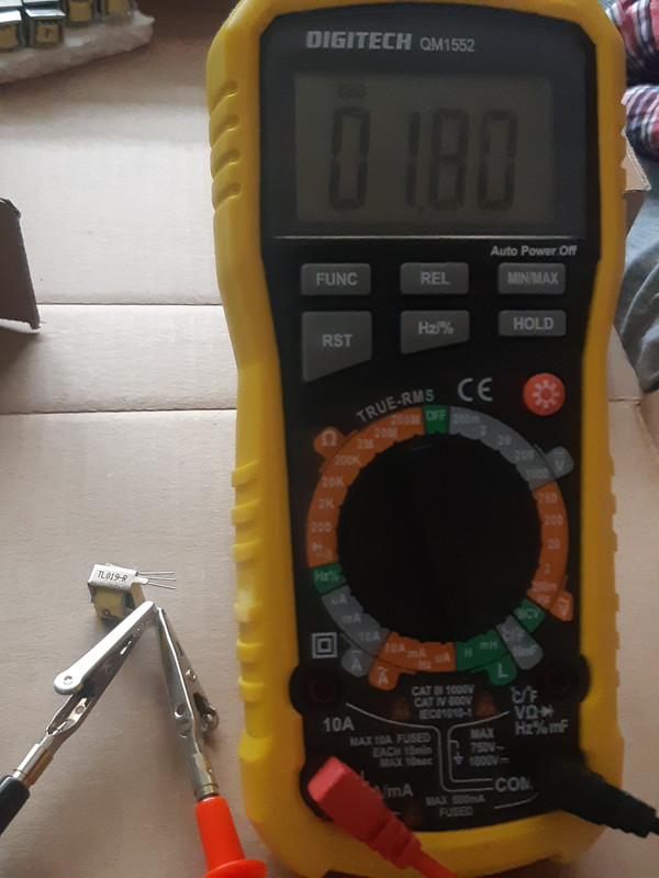 |
|
|
|
Post by frets on Dec 29, 2020 11:30:42 GMT -5
Hi Syddd, Try connecting the primary and secondary as follows and measure again. This view is looking at the transformer from the top. 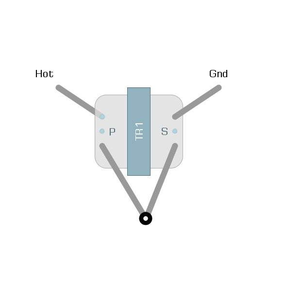 |
|
syddd
Meter Reader 1st Class
  
Posts: 62 
Likes: 10
|
Post by syddd on Dec 30, 2020 5:32:29 GMT -5
Hi Syddd, Try connecting the primary and secondary as follows and measure again. This view is looking at the transformer from the top.  Hi frets, it's 2.7H when I measured though the inductance was dropping as I was holding it stationary. The secondary side only has an inductance of 0.06H however because there's magnetic field interference, the inductance isn't the sum of the two sides of the transformer. This suggests that some of the above listed values for the different transformers are wrong, that mouser have given me the wrong part (I doubt it, though the 42TL019RC inductors I have are labelled TL019-R on the side) or that I have a very dodgy RLC meter! |
|
|
|
Post by frets on Dec 30, 2020 8:17:33 GMT -5
Hey Syddd,
I’ve never had such a problem whereby the inductance plummets on measurement. I’ve had some dodgy meters that have given erroneous measurements but I’ve never had a problem with a Xicon losing its inductance across a measurement. I’ve never encountered a bad Xicon Audio Signal Transformer.
My offer stands as I stated in the PM.
|
|
dccable
Rookie Solder Flinger

Posts: 3
Likes: 0
|
Post by dccable on Jul 23, 2021 10:26:54 GMT -5
Hello all,
I'm new to the forum and hopefully this is not a zombie thread by this point.
My question is has anyone tried to wind their own inductor for Varitone use rather than use these small interstage/telephone transformers? Using TKD parts and #38 awg wire I've wound a 11.5 H 125 ohm DCR inductor that while not 15 H is in the neighborhood. Going with either a bigger core from TKD or smaller wire should get me to 15 H while in the case of smaller wire would increase the DCR.
|
|
|
|
Post by frets on Jul 24, 2021 15:56:45 GMT -5
Hi DC,
The audible difference between an 11.5H and a 15H is going to negligible (in my opinion). I build a lot of Varitones and once you start to get above 4H, it really starts to mess with the overall tone (my subjective opinion). Most Varitones use 1.5H. I go up as high as 3.75H on certain guitars, like hollow bodies. It really is a personal preference and there is no real “magical number.” Since you’re already familiar with winding, why don’t you wind a few, starting with 1.5H and moving up - say 2.5H, 4H, 5H and then compare those to your 11.5H. I’m suggesting a bench test. I would hate to see you get the Varitone in there at 11.5H and not find it all that interesting. The higher you go seems to affect the lower cap values (.0033 as an example), whereby the inducted effect just doesn’t differentiate until you get up to around .022 (again, my opinion). What I’m saying is the higher you go on Henries seems to obliterate the differences of uF value on the smaller uF caps. Please experiment with it. I believe you might just like a smaller H.
|
|
dccable
Rookie Solder Flinger

Posts: 3
Likes: 0
|
Post by dccable on Jul 25, 2021 20:58:39 GMT -5
Here are some screen shots of FFT analyzer plots of the Varitone I built with the 11.5 H inductor I wound.
Questions/comments welcome
     |
|
sapristi
Rookie Solder Flinger

Posts: 2
Likes: 0
|
Post by sapristi on Sept 27, 2023 9:55:16 GMT -5
Hi all! Reviving this thread because I'm trying to build a varitone for a homemade guitar. Would love some comments to know if anything is wrong here. (First time making a varitone but not the first time making effects in general, fortunately.) I've got a 15H inductor here and I'm not afraid to use it. First of all I blindly replicated the values in the original Gibson schematic, i.e. : • L = 15H • R = 100K • C = 1n / 3.3n / 10n / 33n / 220n The result was lacklustre. The scooping effect was really quite subtle and seemed to affect frequencies that aren't the most interesting. I heard a cut in high treble in all settings, cool and useful for rounding out overly spikey overdrive, but the midrange effect was not very noticeable in any setting. I could hear the changes in frequency, though, when putting my finger on a component to make a bit of white noise and turning the switch to hear it go from low "ooh" to higher "ooh" to "aah" etc. Only then did I do a bit of studying. I found this thread and had a go at working things out on paper. Calculating the frequencies, these are the (rounded) frequency peaks I had with the aforementioned setup : - 220n → 87 Hz - 33n → 226 Hz - 10n → 411 Hz - 3.3n → 715 Hz - 1n → 1.3 kHz This is weird to me, since I would have supposed that more "vocal", wah-like frequencies between, let's say, 800 Hz and 3kHz would be more interesting, but the other sets of values mentioned here, including frets 's setup a few blocks above with the 3.75H, are more focused around ~200 to ~600 Hz. (side note : when listening to varitone demos on youtube, I feel like the higher the setting, the more mids get scooped out. Is this because the Q factor increases when C increases??)
Then I realized something else : the difference between a circuit that uses 1.5H and 15H, apart from a 10x difference in the cap values needed to attain the same frequencies, is also a 10x difference in Q factor. I'm a bit out of my depth here, but am I right in thinking this is the reason why I can't hear the effect all that much in my 15H build? I hope someone can come in with an answer here, although I know I'm more likely to advance by the time a response comes along. Since the 100K resistor seems to affect the Q, and frets mentioned leaving it out, I'm gonna try testing the circuit again with a 1M pot instead, as a variable resistor. This way I can go all the way from "1M resistor" (which would give me the same Q with this 15H as with the 1.5H build for the same frequency) down to "no resistor" (→ massive Q). I really hope this Q stuff is the key. Will report back. |
|


 to Guitarnuts2.


