|
|
Post by solderburn on Nov 9, 2018 11:50:23 GMT -5
that multimeter looks like one I got free with a coupon at harbor freight. I'm pretty sure I trashed a perfectly good pickup because it gave me a faulty zero resistance reading (meaning that there was a break somewhere inside the coil). I don't think the meter even turns on for me anymore what I'm getting at is that a cheap meter may create more headaches than solve problems (even my $20 radio shack meter gives faulty readings instead of tell me that the battery is almost dead...) beyond that, make sure batteries are good and that you're clicked on the right range (otherwise it may give a faulty reading) Thanks, thetragichero, yes, indeed you are correct, it's a free one, I'll be getting a better one today after work. My first instinct when i wasn't getting the expected readings was to check it's batteries, but there's no internal access unless i have a special triangular shaped screw driver as it seems it's a terrible design and not even worth it's free price tag. I should've known. ha I was able to get an actual reading from a pickup that wasn't wired, so i assume this multimeter is actually working for now, but i know i need a slightly more reliable one if i want to move forward without any doubts. This job deserves a new toy, i mean... tool. |
|
|
|
Post by newey on Nov 9, 2018 14:29:02 GMT -5
Back to solderburn's last question:
What's available to you may depend upon where you are in the world. And, while we can help you search, here are a couple of tips as you look around the web:
First, try electronics suppliers rather than guitar parts websites. You'll have a better chance of finding what you need, and it will probably be cheaper. Mouser.com has always served me well.
Second, most online sellers will have a link in their item description that links to the switch manufacturer's product data sheet. That's where you'll find the detailed info on the dimensions and electrical operation of the part in question. Usually, most manufacturers will have a small graphic representation of the switchs operation as well as a schematic.
|
|
|
|
Post by solderburn on Nov 9, 2018 15:50:09 GMT -5
Newey, thanks for the tips and pointing me in the right direction. Will do.
|
|
|
|
Post by solderburn on Nov 13, 2018 13:20:52 GMT -5
Quick little update: I got a new multimeter for about $35, it works very well and I'm pleased i got it. Also it confirms that i was truly getting no readings from the pick ups that I wired in the guitar, so that means i did something very wrong somewhere, of course. I assume/hope it's from me using the wrong switches. After some searching i think i found a 4pdt on-on-on toggle switch that's in line with what the diagram called for. It's actually one i had been considering before i got the wrong switches! And I'd prefer slide switches instead of toggles, but i couldn't find any with the requirements. Not a big deal though. Here's the one i think might work, i looked at the datasheet and maybe i missed the info in the schematic, but i didn't see an explicit up-down-up-down description, but after looking at the chart of positions it looks like it could work. I'm hoping someone with a better understanding could confirm that this is the appropriate switch... www.mouser.com/ProductDetail/E-Switch/1004P6T1B4M7RE?qs=sGAEpiMZZMvudeGI7i40XDvxiNc96yn3QelIXAAmzh0%3dAnd half the price too! I also like that smaller toggle, as where the ones I've currently wired seem a little crowded for this application of have 3 side by side. Just personal preference, of course. Thanks again, Newey, for pointing me to mouser.com, bookmarked. |
|
|
|
Post by newey on Nov 13, 2018 23:02:55 GMT -5
Per the Datasheet, it looks like that's the one- up,down,up,down But see for yourself. You linked to the 4P6 version, which is the On-On-On version with no momentary-actuated positions. And, here's the pertinent info: 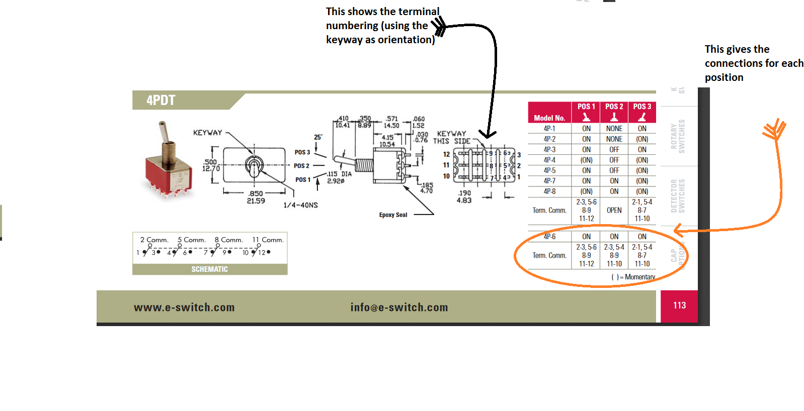 |
|
|
|
Post by solderburn on Nov 14, 2018 11:04:26 GMT -5
newey, thanks for confirming that, and showing me exactly how to read the info on the datasheet! Super helpful.
Looking forward to round two.
|
|
|
|
Post by solderburn on Dec 16, 2018 21:00:53 GMT -5
Hi all,
After i received the switches from mouser i could see that i had ordered the wrong ones. Despite most specs being correct i didn't notice that particular switch had right angle terminals and no threading for nuts for attaching to the pickguard. Totally my fault. The folks at Mouser.com were excellent about replacing them and helping me find the perfect part number i needed, and i feel like a total fool because i really should have seen that in the very first thread by aroberts8089 there is the exact same switch that he suggested for use. I'm learning though, slow down and re-read. Mouser sent the correct switches only to have one of the toggles to be defective, in that it was getting jammed in one position, luckily i spotted this before i wired anything. Mouser again was very helpful to replace the switch with a good one.
I'm ready to wire it up again. But i after re-reading through the previous threads that go over this wiring, i noticed that Yogi B brought up a good point that it would probably be better to have the off position in the middle, and have the on and oop to be in the far up and down positions of the switch. This isn't a deal breaker for me, but i do agree that it's a more practical layout than original configuration, for me at least. I saw Yogi B made this change in his adaption that uses 3P3Ts instead of 4PDTs, but is this possible with using the 4PDTs? If so then would anyone be willing to please draw a diagram that features the off position in the middle instead of the up position? I'd be more than grateful. If it's too much trouble than i totally understand and will proceed to wire it as things are currently.
Thanks for your consideration.
|
|
|
|
Post by thetragichero on Dec 16, 2018 22:32:31 GMT -5
I have more than a few smd op amps/transistors that I've orders by accident from mouser. never even thought about trying to send them back
|
|
|
|
Post by solderburn on Dec 16, 2018 22:47:46 GMT -5
I have more than a few smd op amps/transistors that I've orders by accident from mouser. never even thought about trying to send them back I offered to send them back but they told me to just keep them as the shipping costs make it not practical for returns. They just credited back my money and i paid difference for the correct switches. Mouser.com really took care of me and i plan to be a customer for life. And i would've just kept the wrong switches but I'd already spent about $100 on my first set of toggle switches that i already had soldered. And these newest switches came to another $100, that's funny because the guitar i'm modding only costed me about $120. |
|
|
|
Post by thetragichero on Dec 16, 2018 23:51:02 GMT -5
welcome to the club!
I've bought a few $40 strat copies just to throw almost $200 worth of pickups in em!
|
|
|
|
Post by Yogi B on Dec 17, 2018 0:46:20 GMT -5
I'm ready to wire it up again. But i after re-reading through the previous threads that go over this wiring, i noticed that Yogi B brought up a good point that it would probably be better to have the off position in the middle, and have the on and oop to be in the far up and down positions of the switch. ... I saw Yogi B made this change in his adaption that uses 3P3Ts instead of 4PDTs, but is this possible with using the 4PDTs? Not as far as I know, or expect it to be, but I don't know that it's been proven impossible yet. (It could be done with 3 4PDTs and a larger switch for the series/parallel toggle, but I suspect it'd need to be a 8PDT or 8P3T.) (Ultimately I decided on a different approach, but my goals were different as the design was for 3 humbuckers. I used the 4PDTs to switch each HB between off, local parallel, and local series, a 5-way superswitch for the phasing, and only had the two position global series-parallel switch).
Also, before heating up the iron, have you seen my more recent updates in that thread? There is: a functionally equivalent version but with slightly simpler wiring; a version that aims to make the centre B×M+N position behave a bit better (but it's still not perfect); and a version that forgoes the B×M+N idea altogether, instead opting to give an easy way to swap to just one coil selected. |
|
|
|
Post by solderburn on Dec 17, 2018 1:21:40 GMT -5
Thanks Yogi B for your quick and helpful reply. Much appreciated. And yes, thanks, i saw your latest iteration of this wiring. I'll try to do it that way. I think it's amazing that you can figure these things out without having to actually build them. This is the one i'll try to do...  |
|
|
|
Post by solderburn on Jan 6, 2019 23:07:44 GMT -5
Happy new year, my fellow guitar nutz! I hope you're all doing well. The other day i was listening to this... and thought of us nutz. I'm reporting back to ask for help. I recently was able to wire up this monstrosity and i know i've made some fatal flaws. Firstly, i think i must be reading the diagram wrong because I'm getting sound in some of the PU settings, but the selection isn't behaving as intended and there seems to be many setting where it's very quiet. Things just don't make sense to me. I referred to JohnH's trouble shooting instructions: "The simplest best most informative tests you could do now are with the multi meter. Set volume and tone to max, strangle to normal mode. Set the meter to a 20k Ohms range (use 200k if it goes off scale) connected between hot and ground at the jack. Then just methodically cycle through each setting of pickups on or off, in series or parallel. That's 16 (out of the possible 81) readings, write down and post them here. As you do them, just confirm that 'on in phase' and 'on out of phase' never makes any difference to the resistance." I attempted to get multimeter readings of the PU selections, although i couldn't figure out what 16 settings i'm supposed to get a reading for. I'm an idiot so please have patience. If anyone could tell me which 16 settings were needed then I'd be grateful. I could only come up with 14 settings, including all off. So I just made a chart of all the settings i could come up with of since i wasn't sure exactly what i should do. All settings are with the strangle switch not engaged, and with volume and tone rolled all the way up. I got 4 readings for each setting, the first reading is made in the parallel selection starting by engaging the PU with the PU toggle switch all the way down, then the second reading is with the toggle switch in the middle position (or just opposite if it's an oop phase setting). The third and fourth readings are the same pattern but in series mode. Sorry if i'm confusing.   I couldn't figure out how to do the volume sweep test as i couldn't find a 2M ohms scale in my multimeter. But when the guitar is plugged in the volume knob sounds like it's working as it should, and still quite usable despite it having a linear taper. So, as far as i can tell, the strangle switch, volume, tone, and killswitch all seem to work as they should (and sounds really fuggin cool). As you can probably tell from the ohm resistance readings a few of the PU selections sound okay, put for sure it's not working as it should. I hope the readings will give you wizards some insight as to what i did so wrong. I think i might've done everything backwards, or upside down. It hurts my brain to think of it. I already ordered a solder sucker and it should be arriving this week. I have a feeling i'll probably be re-doing every single connection. Here are some pics of the inards, it's such a bundled jumble that of course it's impossible to follow any lines, but maybe you can see a glaring mistake that i'm totally overlooking. I thought i wired it as per the diagram in the above post.    Thanks in advance for any and all assistance. |
|
|
|
Post by JohnH on Jan 7, 2019 14:58:51 GMT -5
The 16 settings that I was referring to were to take just the up and down settings of tbe four switches (ignore the middle settings, we know there are issues with that due to the different switch types as identified by Yogi).
With two such settings per switch, up and down, there are 2x2x2x2 = 16 settings to test. They are not all different sounds though.
From the readings so far, those less than 1k likely indicate a problem.
|
|
|
|
Post by solderburn on Jan 7, 2019 15:41:28 GMT -5
The 16 settings that I was referring to were to take just the up and down settings of tbe four switches (ignore the middle settings, we know there are issues with that due to the different switch types as identified by Yogi). With two such settings per switch, up and down, there are 2x2x2x2 = 16 settings to test. They are not all different sounds though. From the readings so far, those less than 1k likely indicate a problem. Thank you, JohnH, for explaining that. And I think i should mention that i got all new switches since the first time you helped me. So right now it's currently wired with the correct switches as called for in the diagram. At this point I strongly believe the problem is due to me not reading the diagram correctly. Not sure where to go from here. Maybe this project is just too far beyond my current skill level. |
|
|
|
Post by JohnH on Jan 7, 2019 15:54:17 GMT -5
If you could set out yr readings for those 16 settings, we might spot something.
Call the switches say, B,M,N and S/P
Do a table of resistance measurements that goes, eg:
down down down down
down down down up
down down up down
down down up up
down up down down..
....etc
|
|
|
|
Post by solderburn on Jan 7, 2019 15:57:32 GMT -5
If you could set out yr readings for those 16 settings, we might spot something. Call the switches say, B,M,N and S/P Do a table of resistance measurements that goes, eg: down down down down down down down up down down up down down down up up down up down down.. ....etc For sure. Will do. I'll report back with those. Thank you. |
|
|
|
Post by Yogi B on Jan 7, 2019 16:10:37 GMT -5
I got 4 readings for each setting, the first reading is made in the parallel selection starting by engaging the PU with the PU toggle switch all the way down, then the second reading is with the toggle switch in the middle position (or just opposite if it's an oop phase setting). ... Sorry if i'm confusing. Yeah, that is quite confusing, and also ambiguous: for example in row 4, B+M, which toggle is in the middle the one for the bridge or the one for the middle? Your upcoming table should be of more help. Nevertheless, here's my attempt a filling in some of the blanks, with what you've done so far: | Parallel | Series |
|---|
| Pickup | Normal | Reverse | Normal | Reverse |
|---|
| 1 | B | 11.16 = B | 11.19 = B | 11.26 = B | 11.28 = B | | 2 | M | 6.18 = M | 0.60 | 6.21 = M | 0.60 | | 3 | N | 5.89 = N | 0.50 | 3.04 = M+N | 0.59 | | 4 | B + M | 3.99 = B+M | 0.52 | 17.33 = B*M | 11.91 = M*N | | 5 | B + N | 3.89 = B+N | 0.47 | 14.24 = B*(M+N) | 11.88 = M*N | | 6 | M + N | 3.02 = M+N | 0.49 | 6.22 = M | 0.61 | | 7 | B + M + N | 2.38 = B+M+N | 0.48 | 17.34 = B*M | 11.86 = M*N | | 8 | (b) + M + N | 2.39 = B+M+N | 0.54 | 17.38 = B*M | 11.86 = M*N | | 9 | B + (m) + N | 0.01 | 0.01 | 11.29 = B maybe? | 17.93 | | 10 | B + M + (n) | 0.01 | 0.01 | 17.91 | 11.30 = B maybe? | | 11 | B + (m) | 0.58 | 4.02 = B+M | 11.83 = M*N | 17.35 = B*M | | 12 | B + (n) | 0.55 | 3.89 = B+N | 11.83 = M*N | 14.27 = B*(M+N) | | 13 | M + (n) | 0.01 | 0.01 | 6.85 | 0.01 |
I've colour coded it as follows: blue are what I've assumed are the correct values for the individual pickups; green are the positions which appear to be correct; red are the positions which appear incorrect; the three I've highlighted in darker red are quite confusing as I can't really infer what they'd be at all. That is, I suppose, until we consider that some of those measurements less than one 1k are 470-610 ohms which isn't insignificant, sure there's 120 ohms difference between the measurements that are all supposed to be the bridge pickup, which I'm willing to hand wave away, but this is quite a bit more. Also of note is that the in phase and out of phase readings are (and should be) kinda symmetrical (e.g. compare rows 4 & 11, or 5 & 12), but this breaks down when comparing row 6 to row 13. Additionally, while there's a lot of red in that table, it could be down to, say, only a couple of misplaced connections. |
|
|
|
Post by solderburn on Jan 7, 2019 17:30:03 GMT -5
I got 4 readings for each setting, the first reading is made in the parallel selection starting by engaging the PU with the PU toggle switch all the way down, then the second reading is with the toggle switch in the middle position (or just opposite if it's an oop phase setting). ... Sorry if i'm confusing. Yeah, that is quite confusing, and also ambiguous: for example in row 4, B+M, which toggle is in the middle the one for the bridge or the one for the middle? Thanks Yogi B, there is some hope. And for row 4, both are down in the first reading which gave me 3.99, then for the second reading both were in the middle, which i thought should give me the same reading since both should still be on and in phase, but the reading i get for B+M on in the middle position is 0.52. If if only one of the toggles were in the middle then i assumed that would be out of phase and not just B+M. Here's two pics of what i meant to say. I get 3.99 in this position (all the way down)...  And then i get 0.52 in this position (middle)...  And i must be living in the twilight zone over here because now my multimeter won't give me any readings in the 20k setting, but last night it was working. I tested the battery and it's good. I guess that's a whole other issue. I think maybe i'll be getting another multimeter. I cannot believe this. Once i get straightened out with the multimeter then i'll post the 16 helpful readings. Thanks again to for everyone's help and patience with this. |
|
|
|
Post by solderburn on Jan 7, 2019 18:03:18 GMT -5
Okay, here's what i got for the 16 readings. I used the 200k ohms setting because for some reason now i'm getting "0.L" when i use the 20k setting. Man, i don't know what's going on.
The first switch is the series parallel global toggle, second switch is Bridge PU, third is middle PU, fourth is Neck PU.
1 DDDD 62.9
2 DDDU 62.9
3 DDUD 60.1
4 DUDD 53.0
5 UDDD 49.6
6 DUUD 50.2
7 DDUU 57.5
8 UUDD 50.2
9 DUDU 53.0
10 UDUD 51.0
11 UUUD 52.8
12 UDUU 57.5
13 DUUU 47.5
14 UUDU 53.0
15 UDDU 62.9
16 UUUU 47.5
I thought having them all up (off) would make for a zero reading, but no. But when i hit the killswitch it goes to zero, not sure if that info helps.
|
|
|
|
Post by Yogi B on Jan 7, 2019 18:58:20 GMT -5
I used the 200k ohms setting because for some reason now i'm getting "0.L" when i use the 20k setting. Man, i don't know what's going on. That's because all the readings are greater that 20k, which they shouldn't be. Was the volume still set fully to maximum? Nudging a 1Meg (linear) volume pot down a tiny bit to 9.5/10 would tally with your latest readings. |
|
|
|
Post by solderburn on Jan 7, 2019 19:04:03 GMT -5
I thought the volume was all the way up. As i'm doing these tests and getting odd readings i've gone back and made sure the volume was all the way up.
Also, it seems my new multimeter is fine, no surprise that it's the guitar that's causing the weird fluctuating readings. I know this because i tried the multimeter on a squier bass 6 with the same type of PUs and was able to get stable readings in 20k.
It's very inconsistent. Now when i try the DDDD position i get a fluctuating reading of about 26 to 28, not settling on a number, and not reliably going back to a previous setting after moving a switch. I'm so confused. I think this is what happens when i'm in over my head. I'm trying though.
|
|
|
|
Post by solderburn on Jan 7, 2019 20:19:25 GMT -5
Okay... i'm getting somewhere. I opened up the volume/tone circuit and just sorta moved things around with my finger, maybe a wire was touching or something, i don't know, but now i can at least get solid, nonfluctuating readings from the all the positions while in the 20k setting! WOW!
Now i must check on my cats, but when i get back i'll re-do the 16 positions with proper readings.
|
|
|
|
Post by Yogi B on Jan 7, 2019 20:24:59 GMT -5
Now I'm convinced your volume was on 95% in you previous readings. Applying a little bit of maths to work out what the value would've been, the numbers seem too close for it to be coincidence: s/p B M N Expected Expected Measured Infered
Pickups Res (k) Res (k) Pickups Okay?
1 D D D D B * M * N 22.93 62.9 -> 17.35 B * M
2 D D D U B * M 17.24 62.9 -> 17.35 B * M Yes
3 D D U D B * N 16.96 60.1 -> 14.16 B * (M + N)
4 D U D D M * N 12.00 53.0 -> 6.13 M
5 U D D D B + M + N 2.39 49.6 -> 2.33 B + M + N Yes
6 D U U D N 5.89 50.2 -> 3.00 M + N
7 D D U U B 11.20 57.5 -> 11.20 B Yes
8 U U D D M + N 3.02 50.2 -> 3.00 M + N Yes
9 D U D U M 6.18 53.0 -> 6.13 M Yes
10 U D U D B + N 3.87 51.0 -> 3.89 B + N Yes
11 U U U D N 5.89 52.8 -> 5.91 N Yes
12 U D U U B 11.20 57.5 -> 11.20 B Yes
13 D U U U None 0.00 47.5 -> 0.00 None Yes
14 U U D U M 6.18 53.0 -> 6.13 M Yes
15 U D D U B + M 4.00 62.9 -> 17.35 B * M
16 U U U U None 0.00 47.5 -> 0.00 None Yes
|
|
|
|
Post by solderburn on Jan 7, 2019 20:37:28 GMT -5
1 DDDD 17.09
2 DDDU 17.07
3 DDUD 14.02
4 DUDD 6.15
5 UDDD 2.36
6 DUUD 5.84
7 DDUU 11.08
8 UUDD 3.00
9 DUDU 6.12
10 UDUD 3.84
11 UUUD 5.84
12 UDUU 11.08
13 DUUU 0.00
14 UUDU 6.12
15 UDDU 3.96
16 UUUU 0.00
That's more like it! All readings done in 20k. with SP as the first switch, then bridge PU for the second, middle PU for third, and neck PU as the forth.
|
|
|
|
Post by solderburn on Jan 7, 2019 20:47:08 GMT -5
Now I'm convinced your volume was on 95% in you previous readings. Applying a little bit of maths to work out what the value would've been, the numbers seem too close for it to be coincidence:
Thanks a lot for applying the maths to get to the bottom of it. And i swear i physically had the volume set as far as it could roll, but something else was causing it to behave as if it were at 95%. I totally agree with you, and it's something i can't explain that was making it not work correctly, only after i opened up the master circuit did it start behaving as one would expect. Maybe some sort of grounding short, i have no idea. It's also odd that even when i was getting the wonky readings i was able to plug it in to an amp and it sounded as it usually does with some settings not working but some sounding okay. Thanks for all your time and thoughts on this, Yogi B. It's highly appreciated!! |
|
|
|
Post by Yogi B on Jan 7, 2019 20:53:18 GMT -5
With your latest measurements there are two more rows that appear to behave as expected: s/p B M N Expected Expected Measured Infered
Pickups Res (k) Res (k) Pickups Okay?
1 D D D D B * M * N 22.93 17.09 B * M
2 D D D U B * M 17.24 17.07 B * M Yes
3 D D U D B * N 16.96 14.02 B * (M + N)
4 D U D D M * N 12.00 6.15 M
5 U D D D B + M + N 2.39 2.36 B + M + N Yes
6 D U U D N 5.89 5.84 N <Yes>
7 D D U U B 11.20 11.08 B Yes
8 U U D D M + N 3.02 3.00 M + N Yes
9 D U D U M 6.18 6.12 M Yes
10 U D U D B + N 3.87 3.84 B + N Yes
11 U U U D N 5.89 5.84 N Yes
12 U D U U B 11.20 11.08 B Yes
13 D U U U None 0.00 0.00 None Yes
14 U U D U M 6.18 6.12 M Yes
15 U D D U B + M 4.00 3.96 B + M <Yes>
16 U U U U None 0.00 0.00 None Yes
Now we just have to figure out the issue with the positions that remain troublesome, and see if that explains the problems in the middle positions too... |
|
|
|
Post by solderburn on Jan 7, 2019 23:52:05 GMT -5
Great, thanks!
I'll take the pickguard off and look at every single connection again, checking for anything that's out of place.
|
|
|
|
Post by JohnH on Jan 8, 2019 2:19:33 GMT -5
The most oddness seems to be around series mode, where neck or neck&middle are involved.
Another useful test is a tap test. You engage a certain combo, and with it plugged into an amp, use a screwdriver tip to lightly tap a pole on each pickup to see which are active. If a coil is engaged, you get a thump at the amp. You could try a few single settings and well-behaved combos, then do it for the combos where the resistance is more than a few hundred ohms out. This should confirm if the active pickups are the correct ones, or not.
|
|
|
|
Post by solderburn on Jan 8, 2019 14:00:13 GMT -5
Thank you JohnH and Yogi B.
That table is very helpful!
I did the tap test and compared all the positions. Of course Yogi B's chart is spot on. Taps confirm that the inferred PUs are indeed correct.
Specifically positions 1, 3, and 4 are bad.
I haven't had time today to look under the pickguard, i hope to get in there tonight after work to see if i can spot the mistakes.
|
|


