|
|
Post by ourclarioncall on Dec 27, 2019 18:13:15 GMT -5
First off I would like to wish you all a very Merry Christmas 🎄 and Happy New year when it comes 🙂. I’d also like to Thankyou all again for your help and patience on my journey, really appreciate the input , thankyou again. I am trying to figure out Brian May style wiring for two single coils. The main difference is I want to have a half out of phase switch as well as a regular out of phase switch, and as you can see I’ve just copied the May wiring and squeezed in extra switches for the half out of phase option. First thing il say is that I think it’s wrong . Specifically the way the half out of phase switch is wired , which I am confident is correct in a parallel wiring scheme , but because this is a series scheme them I’m led to believe the cap has to be wired in parallel , but I have it in series. I think. If I’m right ... that It’s wired incorrectly, then how would I wire it up in parallel ? I’m also assuming that there are no other major problems in the wiring but I’m sure youl point that out . Thanks  |
|
Deleted
Deleted Member
Posts: 0
Likes:
|
Post by Deleted on Dec 27, 2019 19:21:15 GMT -5
Hmm the half phase thing .
Been some time since I used phasing.
But that's on AC electrics to bring big lighting system cost down.
So.. what is really going on here!!!
So your a guitar tutor from Scotland.
And male.
I am electrician from England.
Rules. Two you need to pickups to be able to get out of phase.
There is no half out of phase here (that only applies to AC electrics on a smooth sine wave (I don't want to go deep in to that)
But this is the way
My suggestion look at a lot of circuits , see the difference and then what they did to change it and why.
And don't use American cap values. 0.01uF is 10nF what the rest of the world use!! Including us in the UK!!
Tera 10^12 - Pico 10^-12
Giga 10^9 - nano 10^-9
Mega 10^6 - micro 10^-6
Kilo 10^3 - Milli 10^-3
|
|
|
|
Post by reTrEaD on Dec 27, 2019 20:33:00 GMT -5
First thing il say is that I think it’s wrong . Specifically the way the half out of phase switch is wired , which I am confident is correct in a parallel wiring scheme , but because this is a series scheme them I’m led to believe the cap has to be wired in parallel , but I have it in series. I think. If I’m right ... that It’s wired incorrectly, then how would I wire it up in parallel ? Yes, the capacitor needs to be in parallel with the pickup to do half-out-of-phase when the pickup is combined in series with other pickups. Also ... even if that part of switching worked properly, you'd have to keep track of which of the two phase choices were selected for a given pickup. If both the out-of-phase switch and the half-out-of-phase switch were selected at the same time, the net result would be the pickup would be in-phase but have a high-frequency bypass. Perhaps a bit confusing. The quick answer would be to use a 3PDT switch for the half-out-of-phase but that wouldn't fix the confusion of having two 'phase' switches on each pickup. In my opinion, the best way to deal with this would be to replace the half-out-of-phase switch with a HF-bypass switch. Just a simple SPST switch that places a cap in parallel with the pickup. YMMV. |
|
|
|
Post by ourclarioncall on Dec 27, 2019 21:45:08 GMT -5
First thing il say is that I think it’s wrong . Specifically the way the half out of phase switch is wired , which I am confident is correct in a parallel wiring scheme , but because this is a series scheme them I’m led to believe the cap has to be wired in parallel , but I have it in series. I think. If I’m right ... that It’s wired incorrectly, then how would I wire it up in parallel ? The quick answer would be to use a 3PDT switch for the half-out-of-phase but that wouldn't fix the confusion of having two 'phase' switches on each pickup. *** could I make my wiring work ? Or would I have to go for the 3PDT switch ? If so, where would i attach the cap ? I’m not sure how to wire it in parallel i know this wiring scheme could be more efficient but it a bit of an attempt to try and figure out a way to make things work for myself in a way that makes sense to my brain haha . I now understand there is only a need for one oop switch and one hoop switch but seeing two helps me for some reason. Also I was hoping i would get extra sounds on both neck and bridge when selected individual because of the caps on both the hoop switches . And also I thought that switching the neck hoop switch when both pickups are in series would give me a different sound than if I switch the bridge hoop switch on when both pickups are in series. also this is only half of the circuit , i want to add another section that gets the same sounds but in parallel. Very adventurous I know. |
|
|
|
Post by ourclarioncall on Dec 27, 2019 21:57:55 GMT -5
So your a guitar tutor from Scotland. And male. I am electrician from England. Yes, Greetings from north east Scotland where abouts are you ? Im guessing English is your second language? Where are you from originally? i was getting confused with “half out of phase”. I now know it’s nothing to do with phase angle but to do with keeping half the frequencies from getting cancelled out like they would In out of phase wiring |
|
|
|
Post by ourclarioncall on Dec 27, 2019 22:07:52 GMT -5
Also just to add, I’m not too bothered at this stage about whether the sounds sound good, or if the wiring could be tidier and refined . My goal is just to find a way to make things work, mainly on my own, but with a few nudges in the right direction when needed.
ive managed to get some basic goals so far of having two sliding single coils to experiment with pickup position and I’ve managed to get series and parallel working , so just want to get the last few possible options such as oop and hoop. I want to do it all with toggle switches , no pots, and wired straight to output jack.
|
|
|
|
Post by reTrEaD on Dec 27, 2019 23:41:29 GMT -5
*** could I make my wiring work ? Or would I have to go for the 3PDT switch ? If so, where would i attach the cap ? I’m not sure how to wire it in parallel If you're bound and determined to have an out-of-phase switch AND a half-out-of phase switch on each pickup (rather than an out-of-phase switch and a HF-bypass switch for each pickup), I thought of a way to do the half-out-of-phase with a DPDT. Replace the link made by the cap with a wire so it has the same X pattern as the out-of-phase switch. Then connect the cap between one of the two poles (doesn't matter which side) and the throw toward the bottom of the page on the same side. The cap will be shorted when the switch is in the 'normal' position and across the pickup when the switch is in the half-out-of-phase position. also this is only half of the circuit , i want to add another section that gets the same sounds but in parallel. Very adventurous I know. The difficulty level for that goes up by a factor of about 10. |
|
Deleted
Deleted Member
Posts: 0
Likes:
|
Post by Deleted on Dec 28, 2019 3:50:26 GMT -5
So your a guitar tutor from Scotland. And male. I am electrician from England. Yes, Greetings from north east Scotland where abouts are you ? Im guessing English is your second language? Where are you from originally? i was getting confused with “half out of phase”. I now know it’s nothing to do with phase angle but to do with keeping half the frequencies from getting cancelled out like they would In out of phase wiring It's not cancelling out but changing the wave . And born in Portsmouth royal navy sprog Your posting at some strange times! 2am 4am! As for my English, I'm dyslexic . I'm not keen on background stories , just get to the point. So that makes my English look a bit short. Best never tell some dyslexic too much personal info (too many crazy people online and dam easy to track people down in the UK thanks to reg for voting records) CircuitLab Falstad try some Circuit simulators |
|
|
|
Post by newey on Dec 28, 2019 9:01:33 GMT -5
RT advised: But that only gives two settings, HOOP and in phase. Clarion wants to have regular OOP as well, as on a BM-style guitar. My thought was that, rather than position the HOOP switch after the phase switch, use the HOOP switch to switch the cap in/out of the circuit when the phase switch is set to the OOP setting. Like this, perhaps? 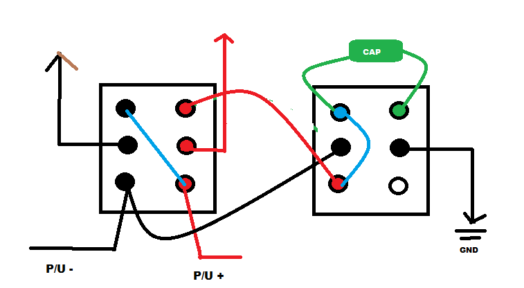 Also, Clarioncall, please abide by what I said elsewhere about using the two quote buttons. Now, not only are you requoting the entire prior post, you are typing your responses into the quoted portion so we can't tell who said what. Just highlight the portion of the prior post you wish to quote, and hit the yellow quote button in the reply box (next to the smiley button). |
|
|
|
Post by ourclarioncall on Dec 28, 2019 9:48:34 GMT -5
RT Brilliant, thankyou I didn’t quite understand the other option ( out-of-phase switch and a HF-bypass switch for each pickup ) so want to try and keep the things I do within the realms of my understanding for just now. Ok, I had a go at redrawing it, have I got the cap in the right place now ?  |
|
|
|
Post by ourclarioncall on Dec 28, 2019 9:51:34 GMT -5
angeIsbunny
ah, apologies, I didn’t realise you were dyslexic.
did you learn electronics in the navy?
i have 5 kids (one an 8 month year old) so posting during the night is normal for me haha.
thanks for the links
|
|
|
|
Post by ourclarioncall on Dec 28, 2019 10:03:51 GMT -5
Newey
apologies again, getting my head round the quoting is on the to do list. I think i did try it and couldn’t get it to work, think I was doing it wrong. Will try it again when I get some time. Busy with 5 kids and all that jazz, can’t get on my own computer! Il keep my reply’s simple for now.
Newey said:
“But that only gives two settings, HOOP and in phase. Clarion wants to have regular OOP as well, as on a BM-style guitar.
My thought was that, rather than position the HOOP switch after the phase switch, use the HOOP switch to switch the cap in/out of the circuit when the phase switch is set to the OOP setting”
Yes that’s right , I want OOP and HOOP. I also heard that there are mods where if you are on just the neck or just the bridge, and flick the HOOP switch, you will get another sound because of the cap. If that’s possible I want it all and I want it now lol. Actually , I’m quite patient and can wait.
the Jerry Donahue telecaster is interesting , it has
1.neck
2. neck plus a cap, makes it sound more humbucker
3. neck and bridge parallel
4. neck and bridge parallel out of phase. The neck has a cap and a resistor. It sound close to the strat 2 or 4 position
5. bridge
here’s a demo of the sounds
|
|
|
|
Post by ourclarioncall on Dec 28, 2019 10:10:23 GMT -5
Newey
forgot to say thanks for sketching up the wiring , looks interesting
I am happy to try whatever works
|
|
|
|
Post by ourclarioncall on Dec 28, 2019 10:47:05 GMT -5
Here is the reference for the guy that claimed you can get two different tones   |
|
|
|
Post by newey on Dec 28, 2019 11:22:02 GMT -5
Clarion-
The diagram I did has the cap switch operate only when the phase switch is set to the OOP setting. When the phase switch is set to in-phase, the HOOP switch is out of the circuit and does nothing. And, we still need someone to double-check my diagram.
You could presumably have the cap available even when in-phase, I'd have to look more closely at that. Be advised that this will cut highs as well as reduce the perceived output a bit. Fender's original Esquire wiring used this type of a "cap bleed" to produce what was described as a "fixed bassy tone" for jazz guitar, although it used a bigger cap value than you are doing.
Your latest diagram still has the cap in series with the pickups, not in parallel. Also, the Jerry Donahue guitar is not analogous to what you're doing, as that involves parallel OOP ("POOP"), you are doing series OOP ("SOOP"). Parallel OOP produces a weaker signal than series OOP, and using the cap in that scenario means less cancellation of frequencies, so a more useable OOP sound.
|
|
|
|
Post by reTrEaD on Dec 28, 2019 11:39:43 GMT -5
Ok, I had a go at redrawing it, have I got the cap in the right place now ? Yes. |
|
|
|
Post by ourclarioncall on Dec 28, 2019 11:45:08 GMT -5
Newey said:
“The diagram I did has the cap switch operate only when the phase switch is set to the OOP setting. When the phase switch is set to in-phase, the HOOP switch is out of the circuit and does nothing. And, we still need someone to double-check my diagram.”
Clarion reply:
gotcha. What if you switch off either the neck or bridge while the phase switch is set to OOP and the HOOP switch is on?
Newey said :
”You could presumably have the cap available even when in-phase, I'd have to look more closely at that. Be advised that this will cut highs as well as reduce the perceived output a bit. Fender's original Esquire wiring used this type of a "cap bleed" to produce what was described as a "fixed bassy tone" for jazz guitar, although it used a bigger cap value than you are doing.”
Clarion reply:
ok. Yeah, I’m familiar with the esquire mods. I wouldn’t mind the high cut and volume drop at this stage
Newey said :
”Your latest diagram still has the cap in series with the pickups, not in parallel. Also, the Jerry Donahue guitar is not analogous to what you're doing, as that involves parallel OOP ("POOP"), you are doing series OOP ("SOOP"). Parallel OOP produces a weaker signal than series OOP, and using the cap in that scenario means less cancellation of frequencies, so a more useable OOP sound.”
Clarion reply: ok. I tried a couple different attempts as wasn’t quite sure what RT meant. I should maybe have put numbers next to the lugs
what I am trying to do with this wiring is only half the circuit, I want to do a similar thing with the parallel sounds too. If I can get the series stuff sorted il then attempt to add in the parallel bit. I know it’s very hard to achieve but I thought if I have it so I have two separate wirings I can choose from by a master switch to send the signal from the pickups to whichever circuit I want to use
|
|
|
|
Post by ourclarioncall on Dec 28, 2019 11:50:01 GMT -5
Ok, I had a go at redrawing it, have I got the cap in the right place now ? Yes. Ah okay, Newey thought this was still in series not parallel I sat and studied this for ages trying to understand it. What exactly is this wiring giving me now ? I want OOP and HOOP . Is that still available of have I lost OOP ? |
|
|
|
Post by reTrEaD on Dec 28, 2019 12:10:24 GMT -5
Ah okay, Newey thought this was still in series not parallel Newey is mistaken about that. The capacitor is in parallel with the pickup, when it is switched to half-out-of-phase. What exactly is this wiring giving me now ? I want OOP and HOOP . Is that still available of have I lost OOP ? The switches nearest the bottom of the page do out-of-phase. The switches near the middle do half-out-of-phase. The switches near the top are on/off. I sat and studied this for ages trying to understand it. Focus on just the switches (with the capacitors) near the middle of the page. You have two wires going to it from the bottom of the page. Basically (-) from the pickup on the left and (+) from the pickup on the right. You have two wires leaving the switch going to the on-off switches. First, evaluate the circuit , when the switch has the poles connected to the lower throws. You can draw in red lines to represent the internal connections. (No change in polarity and no capacitor across the pickup.) Next, evaluate the circuit , when the switch has the poles connected to the upper throws. You can draw in red lines to represent the internal connections. (Change of polarity and the capacitor is across the pickup.) |
|
|
|
Post by ourclarioncall on Dec 28, 2019 12:31:25 GMT -5
RT Ok. Am I understanding this correctly? When both the OOP and HOOP switches are off, is the hot side of the pickup going through the cap like I have drawn ? And if so , will this change the sound a little bit ?  |
|
|
|
Post by ourclarioncall on Dec 28, 2019 12:40:28 GMT -5
RT and when the OOP switch is off but the HOOP switch is on, does the hot signal go through two different paths like I’ve drawn here?  |
|
|
|
Post by reTrEaD on Dec 28, 2019 13:28:56 GMT -5
Let's keep this simple. First: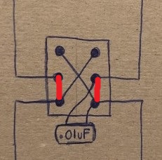 In this position of the switch, the X jumpers don't come into play. - The wire entering on the bottom left is connected (by the switch) to the wire leaving on the left. - The wire entering on the bottom right is connected (by the switch) to the wire leaving on the right. - The capacitor has both of its leads connected to the wire on the right. So it does nothing.
Next: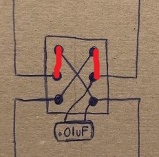 In this position of the switch, the X jumpers are an integral part of the connection path. - The wire entering on the bottom left goes through the jumper from lower left to upper right. then is connected (by the switch) to the wire leaving on the right. - The wire entering on the bottom right goes through the jumper from lower right to upper left. then is connected (by the switch) to the wire leaving on the left. - The capacitor has one of its leads connected to the wire that leaves on the right. It has its other lead connected (via the lower right to upper left jumper) to the wire that leaves on the left. Therefore it is in parallel with the pickup. |
|
|
|
Post by ourclarioncall on Dec 28, 2019 14:13:52 GMT -5
I think I’ve got it. For the most part. When I walked through your explanation it clicked in my brain. Still have a few questions but yeah, i think I’ve got it. So to simplify it , when HOOP is on, it could look like this  or this  |
|
|
|
Post by reTrEaD on Dec 28, 2019 15:10:51 GMT -5
I think I’ve got it. For the most part. When I walked through your explanation it clicked in my brain. Still have a few questions but yeah, i think I’ve got it. So to simplify it , when HOOP is on, it could look like this Yes. I prefer that to the second drawing. Moving the output connections in the second drawing makes it less clear. |
|
|
|
Post by newey on Dec 28, 2019 15:25:02 GMT -5
Yeah, my error, had to draw some red lines of my own to "see" it.
|
|
|
|
Post by frets on Dec 28, 2019 16:20:42 GMT -5
Has anyone mentioned that this all can be accomplished with just six switches?
|
|
|
|
Post by ourclarioncall on Dec 28, 2019 16:28:51 GMT -5
Has anyone mentioned that this all can be accomplished with just six switches? It might be just 13 switches if I can get the parallel section to work 😉 |
|
|
|
Post by ourclarioncall on Dec 28, 2019 16:35:31 GMT -5
Ok, success for the series side. And I think I’m pretty close to getting the parallel side as it’s very similar and I know where to put the cap. So can it be done ? The idea would be that the neck and bridge pickup would go to some sort of switch that could select either the series side or the parallel side . Here’s a very rough sketch to get the jist of it. I’m hoping to get the following sounds 1. neck 2. bridge 3. neck + bridge 4. neck + bridge OOP 5. (neck HOOP) + bridge 6. neck + (bridge HOOP) 7. neck x bridge 8. neck x bridge OOP 9. (neck HOOP) x bridge 10. neck x (bridge HOOP)  |
|
|
|
Post by newey on Dec 28, 2019 19:20:57 GMT -5
I'm just spitballin' here, mind you, until pen can be put to paper, but I think the "?" switch will need to be a 4P2T On-On switch. One pole each to switch between the neck "parallel module" and bridge-side parallel module and neck series module and bridge series module. I don't think a 2 pole switch will do it since the series side will need to be bypassed fully.
|
|
|
|
Post by reTrEaD on Dec 29, 2019 0:26:48 GMT -5
Maybe. But this has the potential to be a massive clusterf*** ... uhh ... problem. - To begin with, your guitar will have a serious case of switch-rash. Thirteen switches for two pickups? seriously? - Your ? switch should have no less than 4 poles, one for each lead of each pickup. - The series section shunts the output if there are no pickups selected. That's good. But if you disconnect that entire section, the parallel side will hum like a gigantic swarm of bees if no pickups are selected. That's bad. Really bad. - If you leave the series side connected when you switch to parallel mode, at least one of the pickup switches MUST be turned on, on the series side, else the output will shunted to ground by the on-off switches on the series side. - And even if one of the pickup on-off switches on the series side is turned on, there will be a capacitor across the entire output if the half-out-of-phase associated with that on-off switch is in the half-out-of-phase position. Personally I think the mode switch (with LOTS of poles) *might* be better placed after the on-off switches and controlling where the half-out-of-phase caps are connected and the shorting of the output. But working out the details would entail much more thought than I'm willing to invest.
Regardless of which path you take, his might be an interesting project for you if you had maybe a year or so of designing wiring diagrams under your belt. But right now, you don't have the skills or foresight to anticipate all the details which need to be addressed. Maybe someone (not me) can guide you through this, but in my opinion, you aren't close to being ready for it. |
|


