|
|
Post by reTrEaD on Jan 24, 2020 17:31:19 GMT -5
The following are Volume Switches, emulating a 250k pot at half-volume (also quarter-volume in the case of the first one with a DPDT on-on-on. Total resistance is slightly greater than 260k, because of the choice to use standard value resistors. Reserved for posterity: If JohnH would be so kind as to run the values through GuitarFreak and get the optimum value for the Treble Bleed cap(s), I'll update the drawings with values for the capacitor(s). 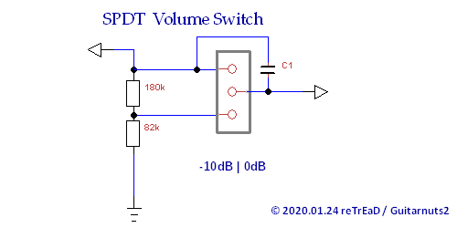 In the following drawing, C 1 alone, is present in the middle (half-volume) position. In the quarter-volume position, C 1 is in series with C 2: 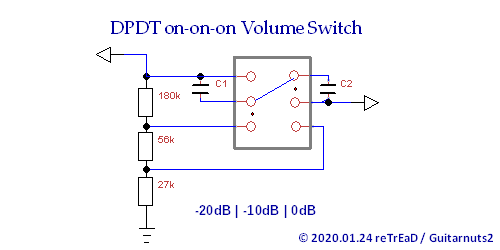 Here we have an off position as well as half-volume and full volume: 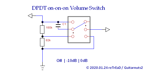 This functions the same as above but has the off position in the middle: 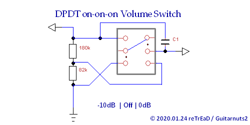 Half-Volume, Full-Volume: 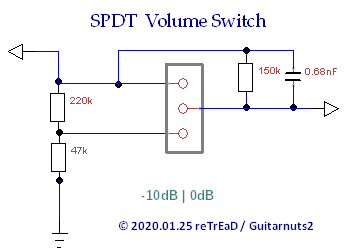 Quarter-Volume, Half-Volume, Full-Volume: 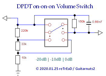 Off, Half-Volume, Full-Volume: 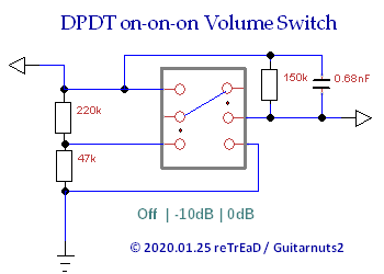 Hald-Volume, Off, Full-Volume: 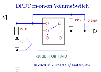 |
|
|
|
Post by JohnH on Jan 24, 2020 19:07:43 GMT -5
Hi reTrEaD - sure, you know I couldn't resist a request like that!
But to do it right, the caps need a resistor in parallel, even when there's a single cap dedicated to one db value. Also, the 20db 10db version is a puzzle, caps end up across different parts of the chain. Back later...
|
|
|
|
Post by reTrEaD on Jan 24, 2020 20:57:09 GMT -5
But to do it right, the caps need a resistor in parallel, even when there's a single cap dedicated to one db value. Hmmm. I thought having a fixed value would mean the parallel resistor wouldn't be necessary. We could just tailor the value of the cap to suit that particular situation. But if it's necessary to have a parallel resistor (which would among other things, increase the loading of the pickup in the lower volume setting), then I suppose I could recalculate the attenuation after the fact. Also, the 20db 10db version is a puzzle, caps end up across different parts of the chain. Back later... Yes, I just noticed that. In two positions, there is no issue but in the third it does get a bit snarly. With the toggle down (both upper throws selected) and full volume, both caps are shunted by the switch. Life is good. In the middle position (left throw down, and right throw up) C 2 is shunted by the switch and C 1 spans the 180k resistor. Again, very predictable. With the toggle up (both throws down), C 1 spans the 180k resistor and C 2 spans the 56k resistor. I might need to rethink this and come up with a better plan. |
|
|
|
Post by JohnH on Jan 24, 2020 21:33:10 GMT -5
It's possible to configure a dpdt on on on, to act as a 1 pole 3 way switch, then an optimum cap//res can be applied that suits both reduced settings.
I've got some numbers happening, which include allowing for the correction to the db's. The effect of loading is included, in trying go find the optimum recipe. I try to maintain the tightest possible control of relative db s vs frequency, up to about 4khz.
|
|
|
|
Post by JohnH on Jan 25, 2020 6:06:34 GMT -5
How about this: Make a chain of 220k, 33k and 10k for a 3 position 0db, -10db, -20db option, or 220k and 47k for two positions 0db and -10db. Use the switches to select like the wiper of a pot. The treble bleed is a fixed 150k in parallel with 0.68nF.  The 1p3t switch can be made from a dpdt on on on Here are plots for that, based on a bridge Texas Special, 250k pot (which the above series chains approximate), 1M amp input resistance and a 10' cord. The plots show the reduced db's, then again normalised to equal volume to show consistency of tone. The tone is consistent at all settings to within about +/-1 db, up to around 4500hz   The best TB recipes that I could find for the -10 and -20db settings were really similar to each other, so hence they might as well have the same. BTW, with a cap only and no parallel resistor, its possible to creat e a treble peak of the right height, but not at near the right frequency, hence its better to use the parallel TB circuit where possible. |
|
Deleted
Deleted Member
Posts: 0
Likes:
|
Post by Deleted on Jan 25, 2020 8:45:36 GMT -5
 dam blonde bunny forgot first position |
|
|
|
Post by reTrEaD on Jan 25, 2020 9:01:43 GMT -5
The 1p3t switch can be made from a dpdt on on on Hey JohnH, that's already what's happening here, without any caps in the four drawings in my OP. To use a singular TB network to serve both the -10dB and -20dB positions, we would connect it the same way as C 1 in the first and fourth drawing I started with. Then it's just a matter of changing the resistance values.
If there's a better fit for the -10dB, can we start with that? Then ADD a second network across what you currently have as the 33k resistor that would ONLY exist in the -20dB position? Would you be able to evaluate that in GF, or do you not have enough nodes to accomplish that? |
|
|
|
Post by newey on Jan 25, 2020 9:40:12 GMT -5
AB-
Both RT's and JohnH's versions have a setting where the cap/resistor network is bypassed. Yours does not, so not exactly the same scheme.
|
|
Deleted
Deleted Member
Posts: 0
Likes:
|
Post by Deleted on Jan 25, 2020 10:32:56 GMT -5
yep sorry corrected it
|
|
|
|
Post by JohnH on Jan 25, 2020 14:11:01 GMT -5
If there's a better fit for the -10dB, can we start with that? Then ADD a second network across what you currently have as the 33k resistor that would ONLY exist in the -20dB position? Would you be able to evaluate that in GF, or do you not have enough nodes to accomplish that? For -10db, you could have 150k in parallel with 0.82nF instead of 0.68nF. But the greatest difference compared to using 0.68nF, anywhere in the testing band up to 4.5kHz is less than 0.1db, so less than 1/10th of negligible!. GF can only do networks that fit within the circuit diagram arrangements that I've coded, so it cant currently do caps across intermediate parts of the volume pot. These could be investigated using a Spice model. But the results above are a very good match, so Id suggest they are about as good as this can be. |
|
|
|
Post by reTrEaD on Jan 25, 2020 16:59:31 GMT -5
GF can only do networks that fit within the circuit diagram arrangements that I've coded, so it cant currently do caps across intermediate parts of the volume pot. These could be investigated using a Spice model. I might pursue that at a later date. For now, I've updated the OP with diagrams using a single 0.68nF//150k network. |
|
|
|
Post by perfboardpatcher on Jan 26, 2020 5:32:49 GMT -5
GF can only do networks that fit within the circuit diagram arrangements that I've coded, so it cant currently do caps across intermediate parts of the volume pot. These could be investigated using a Spice model. But the results above are a very good match, so Id suggest they are about as good as this can be. All one needs is a pocket calculator and keep the loading (of the pickup) the same. For instance 6dB voltage attenuation with Rs and Cs. Potmeter: 250k External load: 1M || 470pF [^-1] is the button on my calculator for the reciprocal (1/x) 0dB -> 250 [^-1] + 1000 [^-1] = [^-1] = 200 kohms -6dB -> Top: 100 kohms Bottom: 100 [^-1] - 1000 [^-1] = [^-1] = 111.1 kohms Two 220k resistors in parallel for bottom Check: 110 [^-1] + 1000 [^-1] = [^-1] = 99 kohms 0dB -> external capacitance is 470pF -6dB -> ratio bottom capacitance: top capacitance is 1:1 capacitance of bottom and top capacitance in series is 470pF Easy in this case, 2x 1nF  |
|
|
|
Post by ourclarioncall on Jan 26, 2020 12:25:54 GMT -5
Awesome 😎 this is so cool. The switching appeals to me a lot as the volumes are set in stone, easily repeatable, quick to access and I have minimalist tendencies and also switches are more aesthetically pleasing than a bulky pot (to me anyway) 😆
Im surprised that this hasn’t been done before or is more common ? I guess the volume pot has reigned as king for a long time. I have in past weeks searched the web and could not find anything like this , although it might be out there somewhere. Maybe it’s because it’s quite a challenging thing to shape ?
|
|
|
|
Post by reTrEaD on Jan 26, 2020 13:27:24 GMT -5
All one needs is a pocket calculator and keep the loading (of the pickup) the same. Interesting concept, that. By keeping the loading the pickups sees, constant in regards to both resistance and capacitance, and also getting the division ratio correct in regards to both resistance and capacitance, I reckon you could get very good results. But ... Our 0dB switch position requires a 250k resistor in parallel with the pickup and the the External Load connected directly to that. In your -6dB scheme, the pickup must be connected to the input of your network and the External Load is connected to 'A'. Moving both connections can't be accomplished with a single pole, so a double-pole switch would be required. Not a deal-breaker at all, but an added requirement just the same. |
|
|
|
Post by JohnH on Jan 26, 2020 15:00:06 GMT -5
For these switched volume settings, it would be possible to set up a procedure to experiment with a normally wired guitar to find one or two preferred volume settings by feel/listening, then measure the resistance of the guitar without opening it up to determine exactly how the pot is set and so back-figure the required switched resistors.
The starting point is to follow the method of externally measuring the pickup and pot resistance by measuring resistance at full volume, and also at max guitar resistance as you sweep the pot.
|
|
|
|
Post by ourclarioncall on Jan 26, 2020 15:15:05 GMT -5
For these switched volume settings, it would be possible to set up a procedure to experiment with a normally wired guitar to find one or two preferred volume settings by feel/listening, then measure the resistance of the guitar without opening it up to determine exactly how the pot is set and so back-figure the required switched resistors. The starting point is to follow the method of externally measuring the pickup and pot resistance by measuring resistance at full volume, and also at max guitar resistance as you sweep the pot. Cool idea. So basically figure out what specific volume drop or drops you want or actually would use in a real life context then calculate what those actually are That’s a great idea, as I was wondering if I would actually use/want a half volume setting. Maybe 1/3 or 1/4 might be better , but you wouldn’t really know until you play around and figure it out So how would you do this ? Unscrew the input jack plate and measure on the hot and ground with a multimetre ? Not sure if everyone knows who Brent mason is but he has a three pickup Tele. The middle pup is wired to its own volume control and he gets some great sounds by bleeding in a little bit of the middle pup with the bridge |
|
|
|
Post by JohnH on Jan 26, 2020 16:55:22 GMT -5
For these switched volume settings, it would be possible to set up a procedure to experiment with a normally wired guitar to find one or two preferred volume settings by feel/listening, then measure the resistance of the guitar without opening it up to determine exactly how the pot is set and so back-figure the required switched resistors. The starting point is to follow the method of externally measuring the pickup and pot resistance by measuring resistance at full volume, and also at max guitar resistance as you sweep the pot. Cool idea. So basically figure out what specific volume drop or drops you want or actually would use in a real life context then calculate what those actually are That’s a great idea, as I was wondering if I would actually use/want a half volume setting. Maybe 1/3 or 1/4 might be better , but you wouldn’t really know until you play around and figure it out So how would you do this ? Unscrew the input jack plate and measure on the hot and ground with a multimetre ? Not sure if everyone knows who Brent mason is but he has a three pickup Tele. The middle pup is wired to its own volume control and he gets some great sounds by bleeding in a little bit of the middle pup with the bridge OK great, if it's of interest, let's pursue it further, and maybe run a test. The scenario Im thinking of is that you have any kind of normally wired guitar, and you determine one or two volume settings that you want, and then the volume pot or pots are replaced with one of reTrEaD's diagrams. The initial testing is fully from outside of the guitar, measuring resistance across the tip and barrel of a guitar cord plugged to the guitar, so its very quick and easy to experiment with. There need be no unscrewing nor desoldering. The only starting assumptions are; 1. that it currently does not have a treble-bleed circuit (very unlikely on a stock guitar, but if it does, then we need to know what it is. Some in the current US Fender range do have it) 2. tone controls if fitted are wired as usual, with a pot in series with a cap. We need to find out about the pot and pickup first. Procedure:1. What type of guitar is it? 2. What is the min to max scale on the volume knob? eg 0 to 10? or 1 to 10? (or does this one go to 11?) 3. Select one pickup/volume pot using the guitar pickup selector 4. Set volume to max, measure resistance across a plugged=in cord. It will be very close to the pickup resistance, eg like 5k to 7k 5. Sweep the volume pot from max to min, while measuring resistance. It will start as in 4, rise, and then fall to zero. Find the maximum value and record the knob position. This max value will be 1/4 of the sum of pot plus pickup. eg, a 6k pickup and an exact 250k pot will read 256/4 = 64k 6. Repeat 3 to 5 if you have a guitar with two volume pots Now to the actual volume settings: 7. Plug in, turn up and rock out, selecting the first desired reduced volume on the volume knob. Unplug from the amp and measure the resistance again, and record the knob position 8. Repeat for a second volume setting, or for another pickup 9. Post all results 10. DO MATHEMATICS 11. Determine required resistance values If you want to try 1 to 9, I'll do 10 and 11. |
|
|
|
Post by perfboardpatcher on Jan 28, 2020 13:41:49 GMT -5
Cool idea. So basically figure out what specific volume drop or drops you want or actually would use in a real life context then calculate what those actually are That’s a great idea, as I was wondering if I would actually use/want a half volume setting. Maybe 1/3 or 1/4 might be better , but you wouldn’t really know until you play around and figure it out Keep the volume pot and use a switch to switch between max volume and whatever volume you've set up with that volume potmeter is not what you want? |
|
|
|
Post by ourclarioncall on Jan 28, 2020 14:29:49 GMT -5
PBP
All I want is a volume drop option with a toggle switch. No pots involved. Sometimes too much choice is a bad thing. It’s easier if it’s either coke or Pepsi 😃 full volume or half. The circuit I’m working on at the moment is all toggles, well the circuit that the guys on here are helping me with. Once complete I want to try just 5 way switches then just pots. Then I can get into combinations of all three
“The Tenacious Tartan Toggler”
Or
“The stubbornly strict switch”
Then After I get a handle on toggles i will move on to explore other lands....
“The Sinatra Selector” also known as the “I did it my way 5 way or the highway”
And finally
“The Half bake MIXstake”
A.K.A
“The pot shot no plot beginner blender”
|
|
|
|
Post by perfboardpatcher on Jan 29, 2020 14:52:50 GMT -5
PBP All I want is a volume drop option with a toggle switch. No pots involved. Sometimes too much choice is a bad thing. It’s easier if it’s either coke or Pepsi 😃 full volume or half. The circuit I’m working on at the moment is all toggles, well the circuit that the guys on here are helping me with. Once complete I want to try just 5 way switches then just pots. Then I can get into combinations of all three “The Tenacious Tartan Toggler” Or “The stubbornly strict switch” Then After I get a handle on toggles i will move on to explore other lands.... “The Sinatra Selector” also known as the “I did it my way 5 way or the highway” And finally “The Half bake MIXstake” A.K.A “The pot shot no plot beginner blender” Ourclarioncall, PBP, You may call me perf if that's more convenient to you. What's in a name? I think I can come up with a schematic for a 5 way. When ready I will post it in your topic. |
|
|
|
Post by ourclarioncall on Jan 29, 2020 15:59:40 GMT -5
Perf it is 😉
Yeah, that would be great, the more the merrier. I would like to build up a variety of circuits based around a single component type .
I think there was a double barrel wiring on the old guitar Nutz site with two five ways IIRC.
|
|
|
|
Post by ourclarioncall on Feb 2, 2020 17:03:50 GMT -5
Okay, beginning the process on a Cort G210 (G series) HSS guitar   1. What type of guitar is it? Cort G210 G series 2. What is the min to max scale on the volume knob? eg 0 to 10? or 1 to 10? (or does this one go to 11?) 1 to 10 3. Select one pickup/volume pot using the guitar pickup selector Neck pickup selected Middle pickup selected Bridge pickup selected 4. Set volume to max, measure resistance across a plugged=in cord. It will be very close to the pickup resistance, eg like 5k to 7k Neck 3.675 k Middle 3.715 k Bridge 10.02 k 5. Sweep the volume pot from max to min, while measuring resistance. It will start as in 4, rise, and then fall to zero. Find the maximum value and record the knob position. This max value will be 1/4 of the sum of pot plus pickup. eg, a 6k pickup and an exact 250k pot will read 256/4 = 64k Neck 119.5 k (volume at 6) when volume is at 1 which Is the lowest setting it keeps fluctuating between 10 k and 20 k , then started dropping to 9 then to 7.4 k after a few minutes. Not sure why it’s not going to zero ? Middle 119.0 k (volume at 6) same issue when volume is at 1, keeps fluctuating all over the place Bridge 119.6 k (volume at 6) Same issue when volume at 1, keeps fluctuating all over 6. Repeat 3 to 5 if you have a guitar with two volume pots Now to the actual volume settings: not applicable, there is only 1 volume pot on this guitar 7. Plug in, turn up and rock out, selecting the first desired reduced volume on the volume knob. Unplug from the amp and measure the resistance again, and record the knob position 8. Repeat for a second volume setting, or for another pickup 9. Post all results 10. DO MATHEMATICS 11. Determine required resistance values If you want to try 1 to 9, I'll do 10 and 11. |
|
|
|
Post by ourclarioncall on Feb 2, 2020 17:10:23 GMT -5
Still got a few more steps to do and will edit them in later
its my first time using a multimeter so I hope I’m doing it correctly .
the neck and middle pickups seemed very low , but then the humbucker seems reasonable but also maybe a bit low for a humbucker ? Not sure
|
|
|
|
Post by ourclarioncall on Feb 3, 2020 19:17:42 GMT -5
  1.What type of guitar is it? Yamaha Pacifica 2. What is the min to max scale on the volume knob? eg 0 to 10? or 1 to 10? (or does this one go to 11?) 1 to 10 3. Select one pickup/volume pot using the guitar pickup selector Neck SC Middle SC Bridge HB 4. Set volume to max, measure resistance across a plugged=in cord. It will be very close to the pickup resistance, eg like 5k to 7k Neck SC = 5.79 k (volume at 10) Middle SC = 5.67 k (volume at 10) Bridge HB = 11.70 k (volume at 10) 5. Sweep the volume pot from max to min, while measuring resistance. It will start as in 4, rise, and then fall to zero. Find the maximum value and record the knob position. This max value will be 1/4 of the sum of pot plus pickup. eg, a 6k pickup and an exact 250k pot will read 256/4 = 64k Neck SC = 122.5 k (volume at 8) Middle SC = 122.2 k (volume at 8) Bridge HB = 125.2 k (volume at 8) >>> I’m having the same issue I had with the Cort guitar. When the volume pot is turned to its lowest setting it is reading the following Neck SC = 17.8 k (volume at 1) Middle SC = 16.8 k (volume at 1) Bridge HB = 14.3 k (volume at 1) I tried the volume at its its lowest on a few other guitars and it was the same thing , none of them would go to zero. The lowest was a Squier Strat that felt more stable and dropped to about 3.5 k Could it be my multimeter ? 6. Repeat 3 to 5 if you have a guitar with two volume pots Now to the actual volume settings: Not applicable 7. Plug in, turn up and rock out, selecting the first desired reduced volume on the volume knob. Unplug from the amp and measure the resistance again, and record the knob position Didn’t have much time on this today but liked setting the volume at 8 for playing chords and then turning full up to 10 for a nice boost for lead guitar. Neck SC = 122.5 k (volume at 8) 8. Repeat for a second volume setting, or for another pickup 9. Post all results 10. DO MATHEMATICS 11. Determine required resistance values |
|
|
|
Post by ourclarioncall on Feb 4, 2020 14:54:56 GMT -5
  1.What type of guitar is it? Squier Strat (Affinity series) 2. What is the min to max scale on the volume knob? eg 0 to 10? or 1 to 10? (or does this one go to 11?) 1 to 10 3. Select one pickup/volume pot using the guitar pickup selector Neck SC Middle SC Bridge HB 4. Set volume to max, measure resistance across a plugged=in cord. It will be very close to the pickup resistance, eg like 5k to 7k Neck SC = 4.89 k (volume at 10) Middle SC = 4.93 k (volume at 10) Bridge HB = 12.95 k (volume at 10) 5. Sweep the volume pot from max to min, while measuring resistance. It will start as in 4, rise, and then fall to zero. Find the maximum value and record the knob position. This max value will be 1/4 of the sum of pot plus pickup. eg, a 6k pickup and an exact 250k pot will read 256/4 = 64k Neck SC = 140.3 k (volume at 5) Middle SC = 140.1 k (volume at 5) Bridge HB = 141.8 k (volume at 5) >>> I’m having the same issue I had with the other guitars. When the volume pot is turned to its lowest setting it is reading the following. This guitar has been the one that has dropped the lowest when volume at 1. Neck SC = 2.6 k (volume at 1) Middle SC = 2.6 k (volume at 1) Bridge HB = fluctuating 3 to 6 k (volume at 1) I think this Squier Strat has a linear pot instead of audio as the readings rise and fall equally at both ends of the sweep 6. Repeat 3 to 5 if you have a guitar with two volume pots Now to the actual volume settings: Not applicable 7. Plug in, turn up and rock out, selecting the first desired reduced volume on the volume knob. Unplug from the amp and measure the resistance again, and record the knob position I liked setting the volume at 5 for playing chords and then turning full up to 10 for a nice boost for lead guitar. Neck SC = 140.3 k (volume at 5) 8. Repeat for a second volume setting, or for another pickup 9. Post all results 10. DO MATHEMATICS 11. Determine required resistance values |
|
|
|
Post by JohnH on Feb 4, 2020 15:52:59 GMT -5
Thanks for all the numbers! they look fine, and I'll do the maths bit in the next day or so. I've done the first one, just checking it.
All your pots are indicating nominally 500k, but through the readings you can tell very specifically how they vary from that, higher or lower. I agree with your interpretation of lin or log. The only thing I can think of tbat would throw that off would be any existing treble bleed (cap and resistor on the volume pot)
On the zero readings, you can check the meter by setting to the same scale as you usually use, and touch the leads together. This would then read just the resistance of the leads, which might be an ohm or two.
Did you get the nice Fluke meter or the cheap generic one? If you got the Fluke, or another that is auto-ranging, could it be that as it gets to very low resistance, it is reading on a different very low scale ie ohms instead of Kohms? I don't have an auto-ranging one myself, but there should be some indication in the display.
Non autoranging meters, if set on like a 20k or 200k max scale, should read as zero when touching leads together.
|
|
|
|
Post by ourclarioncall on Feb 4, 2020 15:53:16 GMT -5
I’m still considering what volume drops I would actually use in real life .
i haven’t done any testing in a band context yet, only in My guitar teaching room. On analysis , I tend to set the max volume at the amp , not with the pot.
I tried two les Paul type guitars to see how much of the neck pup I might bleed into the bridge to get some interesting tones (similar to what Brent mason does with his Tele , bleeds a little of the added middle pup to the bridge ) but when one of the volume pots went down to 1 then the other pickup went off too. So I couldn’t have just one pickup on and then slowly bleed in the other .
I would like to try this on a Strat. 2 single coils with their own dedicated volume pots and try bleeding in a bit of middle or neck with the bridge
then whatever amount is pleasing could be assigned to a setting on a toggle switch .
I originally thought just half volume switch for each pickup would be a good starting point but who knows , you maybe only need to bleed in a tiny bit of other pickup get something desirable
|
|
|
|
Post by ourclarioncall on Feb 4, 2020 16:11:18 GMT -5
JohnHThank John. No rush for that, take your time. 500k pots ? That’s surprising, i just thought 250k would be the norm for all Strat type guitars , but oh, these have a humbucker in the bridge so I suppose that makes sense then. I’m a poor man with expensive tastes haha, a bad combination. I went for the fluke. It has a nice feel, glad I got it. Il check the leads and the readout on the screen and report back
|
|
|
|
Post by ourclarioncall on Mar 14, 2020 21:23:40 GMT -5
I recently installed two of the “half volume , full volume “ switches in my guitar and am enjoying using them . One for each pickup on a two single coil guitar
I was thinking about adding in another two , but at say “quarter volume, full volume”
Then I could have a few more options to experiment with
Here is my main question- what would happen if I had both a half volume AND a quarter volume switch on at the same time on the same pickup ?
For example say my single coil went straight to the half volume then to the quarter and I engage the half volume first the the quarter volume after the half .... will I end up getting a quarter of the half volume that is left ?
I hope I’m making sense !
Or you could wire the quarter volume first in line then the half . Would I be getting an eighth of full volume because half of a quarter is an eighth ?
I think my first example would also be an eighth as a quarter of half is an eighth
|
|
|
|
Post by reTrEaD on Mar 14, 2020 22:47:33 GMT -5
For example say my single coil went straight to the half volume then to the quarter and I engage the half volume first the the quarter volume after the half .... will I end up getting a quarter of the half volume that is left ? Yes. Or you could wire the quarter volume first in line then the half . Would I be getting an eighth of full volume because half of a quarter is an eighth ? I think my first example would also be an eighth as a quarter of half is an eighth Yes. When only one pickup is selected, it wouldn't matter whether the half-volume or quarter volume was the first in the chain. But when both pickups are selected, it matters. Particularly when the pickups are combined in parallel. |
|