|
|
Post by ms on Feb 28, 2022 10:35:56 GMT -5
What an interesting idea: adding current to the material that establishes the equivalent of no boundary. I see that his write up says to set the direction as well as the magnitude of Hc. I do not see where you do that, and so I assume that this has defaulted somehow (or I missed it)?
If you subtract the uniform field from the result of, for example, the case you show above, and then examine it near the "boundary", then it should tend towards a simple result, the 2D equivalent of "All magnetic fields are dipole if you get far enough away." This would allow testing the method, at least down to the limit where the result turns into numerical noise.
|
|
|
|
Post by ms on Feb 27, 2022 21:28:25 GMT -5
Would you say that with the +10dB measured increased output that if you switch between a regular Strat pickup and these, that it increases the output volume by a noticeable amount? I'd be interested in checking them out, both to use and look at them closer. Are you willing to sell a set of three? I understand that with all the parts involved you'd probably not sell them for as cheap as what might be expected of typical Strat pickups. It seems like a big increase in output to me, and so the measured nearly 10db did not seem surprising. I have some prototypes. Could I send them to you to try out? Some of them mount from the bottom, not the middle; that might be necessary in some guitars. I do not have that kind of mounting perfected yet, but it works. A couple of them are tap sensitive because of poor connections between ferrite pieces. That might reduce the hum rejection a bit, too. But they should be good for measuring and checking out on a guitar. |
|
|
|
Post by ms on Feb 25, 2022 10:08:12 GMT -5
In the discussion in the pickup forum, I mentioned that the field resulting from the thin neos on top of the ferrite blade falls off more quickly than that of an AlNiCo pole piece. Here are the results of FEMM models. The model for the blade is actually that for an infinitely long blade because of the 2D solution, but it should be good except near the ends of the real blade. The AlNiCo pole piece is modeled with the cylindrical mode. The 1D plots are the result of selecting a "contour" above the pole. The two vertical scales were different, and so I squashed one and stuck it on top of the other. Thus the two can be seen together. As expected, they are nearly the same at large distances, but the blade with neo is stronger for short distances. The neo case is a bit stronger than I measure; maybe the magnets are not N42 grade as they should be (and used in the model), or maybe my simple minded linear model of the ferrite permeability is not accurate enough.
 |
|
|
|
Post by ms on Feb 23, 2022 6:10:30 GMT -5
If the extra 10db also appears in the sensitivity to string movement then it would be possible to greatly reduce the coil windings and lower the impedance of the pickup so that it could be used with a lower value volume pot such as 22k or 47k and be almost unaffected by the cable capacitance while still fully driving a normal guitar amp. Yes, but to keep the standard strat sound, you would have to: 1. Use larger wire (to occupy approximately the same space) to keep the Q up. 2. Add parallel C (before the volume control) so that the cable C and additional C together would give the correct resonant frequency. My gut feeling is that keeping the inductance at the traditional level and getting more output is what most guitarists want. |
|
|
|
Post by ms on Feb 23, 2022 5:39:32 GMT -5
|
|
|
|
Post by ms on Feb 22, 2022 18:06:56 GMT -5
In this post we compare the response to time varying magnetic fields of the Fender-type strat pickup described earlier and the new high-performance pickup also described earlier. The measurements use a driver coil that is small enough so that it covers part of a pole piece of the first pickup. In fact, it sits on one of the pole pieces, neither the tallest nor the shortest. It sits on the plastic face of the other pickup over the ferrite blade, and so the measurements differ a bit in the coil location. The coil is driven by a broad band signal and the response is measured by a cross spectral technique. A very weak drive is used to make the hum, harmonics of 60 Hz, visible. The same level signal is applied to both pickups. The top plot shows the response of the Fender-type pickup. Notice that many hum harmonics are visible. Also notice the response at 800 Hz, at a level indicated by the green line. The lower plot shows the response of the new high-performance pickup. There is no visible hum. The response at 800 HZ is a bit less than 10 db higher. 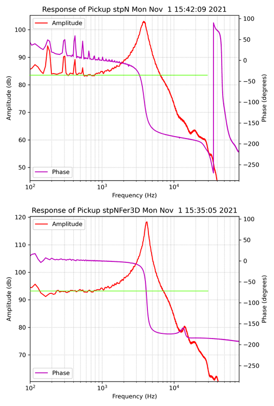 |
|
|
|
Post by ms on Feb 22, 2022 13:03:39 GMT -5
I'd be interested in seeing the output difference, that's what I think of when I think high performance, or the noise rejection ratio if it's humbucking, because for this pickup the high Q factor is impressive but in most cases the Q factor is brought down deliberately. Apparently for guitarists it's not enough to have tone knob, but there must be 125k to 250k ohm permanent load, so that our precious ears are never accidently burdened with the sound of a high Q factor. A few years ago I was trying to create a passive "wah" effect on the guitar with momentary SPST button, but the effect wasn't very pronounced with a low Q factor. The higher the Q factor of the pickup, the better it would have worked. For fun I have tried passive "wah" with pickups with Q like these, and it works well. But what I want from a tone control is Q control, not shift in resonance, and so I do not use a capacitor, but rather a resistor which gives the minimum Q I want to be able to adjust for. So no "wah". The output level is very good; I will try to post the info tonight. |
|
|
|
Post by ms on Feb 22, 2022 7:04:11 GMT -5
excellent work - I too have been experimenting with ferrites and neodynium magnets using a sidewinder design and .04mm copper wire - the limiting factor is the curvature of the strat pickup cover - i had to use 12 2mm diameter neo rods set up like a fender jazz pickup separated by 1mm - initial results are very promising - i used 6000 turns on each coil and stuffed 11 cut off 2.8mm diameter steel nails in each coil to bring the inductance up to 2.6H - the neo rods are 10mm long and so the nails contact the mid point which is neutral magnetically. cheers bajaman
Nice! "Sidewinder" is my favorite pickup geometry; I like the symmetry. But as you say, the curved end of the strat pickup severely limits the space for a "side" oriented coil. So I can see the reason for raising the inductance with the nails. But they are steel, and might lower the Q of the resonance. Have you tried using ferrite instead of nails? |
|
|
|
Post by ms on Feb 21, 2022 18:10:19 GMT -5
The attached plot shows the results of measuring the impedances of a Fender-type strat pickup and the high-performance type (https://guitarnuts2.proboards.com/thread/9862/performance-strat-pickups-pickup-hobbyist). The upper plot is for a strat neck pickup I wound using 8000 turns of #42 wire and AlNiCo 5 magnets. This pickup was made to serve as a reference. In this measurement a voltage is placed across the pickup with a 2K resistor in series. Two voltages are measured: first across this series combination, and second, across the 2K resistor. You can compute the voltage across the pickup and the current through it. A driving signal containing all audio frequencies is used, and computation uses an FFT cross-spectral technique. The lower plot shows the results of the same type of measurement for a prototype of the high-performance pickups with 4500 turns per coil.  The inductances are close, but the capacitances are not. This is expected: fewer turns on a coil means lower capacitance; two coils in series lowers the capacitance still further. We expect the capacitance of the guitar cable to be larger than the coil capacitance, but with these new pickups the capacitance of the pickup itself can be almost ignored. The blue line shows the magnitude of the impedance. The resonant peaks are at different frequencies because the capacitances differ, but also the peak is higher with the new pickup. This indicates that the losses are lower. The Qs at 3 KHz Q are printed on the plots; the new pickup is significantly higher. The purple line is the imaginary part of impedance, modified by removing the effect of the capacitance. As long as this increases linearly with frequency, we have a very simple case: we are just seeing the inductance. But if it curves below the extended straight line, we usually say that the inductance is decreasing with frequency, and this mostly caused by eddy currents in the pickup cores. So in the case of the standard strat pickup, we see this start to happen at 5 or six KHz, significantly higher than we would see with higher conductivity steel cores. But the new pickup has a ferrite core, and we see the linear increase out to 50 KHz, and so we have very low conductivity. I doubt that this difference has much, if any, effect on the sound of the pickup since the frequency is so high, but we can say for sure that the new pickups are no worse in this way. When the new pickup is loaded by the several elements in the guitar circuit, we would expect the sound due to the circuit to be very much like that of a standard strat pickup. The new pickup would require the tone control to be turned down a bit to get exactly the same frequency response. None of this is of any use if the pickup is not sensitive to tie varying magnetic fields. In the next post we compare the sensitivities of the two pickups. |
|
|
|
Post by ms on Feb 18, 2022 10:44:05 GMT -5
Well, as a wise woman once said, put a strat pickup in the sound hole of an acoustic guitar, and the result sounds nothing like a strat. I think what the man in the video has shown (other than how important the characteristics and height of the pickups are!) is that if you fix the relative positions of the nut and bridge very well (open string) when the string vibrates, then you get a particular sound no matter how you achieve that low relative motion. Of course, more generally, it is fret and bridge. On the other hand, when you design the instrument so that there is relative motion and energy goes into the instrument, then there are many possibilities.
|
|
|
|
Post by ms on Feb 13, 2022 13:49:03 GMT -5
This guitar has higher inductance, lower Q pickups:

Neck: 4.37 H 9.32.KOhms 6000 turns #42 wire Middle: 5.57 H 11.16 KOhms 7000 turns #42 wire Bridge: 7.01 H 15.93 KOhms 8000 turns #43 wire |
|
|
|
Post by ms on Feb 13, 2022 10:42:03 GMT -5
I used 1 inch because that was the value used in Tillman's description of sensing width: "This sensing area is called the "aperture" of the pickup and is about an inch wide on a thin single coil pickup and about 2.5 inches wide on a wider pickup such as the Gibson humbucker." www.till.com/articles/PickupResponse/When I use the pole piece width instead, it takes pickup sensing width pretty much out of the equation as a factor in the pickup's frequency response. The pole pieces on my tele bridge pickup are about 5 millimeters in diameter, which yields a first null due to sensing width at over 20k. Even as a low pass filter, the sensing width only decreases high frequency response by a couple of dB by 10k. This isn't necessarily inconsistent with what I see in my data, but detecting sensing width visually in fft graphs is the main thing I am having trouble with. I ran some tests with a string length of 4" (using a dobro capo) and tested it with a tele pickup at 2" and the results implied that the sensing width was 1.14". I did a similar test at the 21st fret and got similar results. I think for the higher harmonics you have to account for damping from bending as well as filtering from spatial sampling. |
|
|
|
Post by ms on Feb 12, 2022 21:18:52 GMT -5
The physics tells you that the sensing width is something like a pole diameter. Why are you using 1 inch? A humbucker has two sensing regions, and that matters for measurements and for the sound on the lower three strings.
|
|
|
|
Post by ms on Feb 12, 2022 12:29:44 GMT -5
Here are three pickups in my test strat. The middle one is the one with the finished top described earlier. The other two just have the surface the printer made.
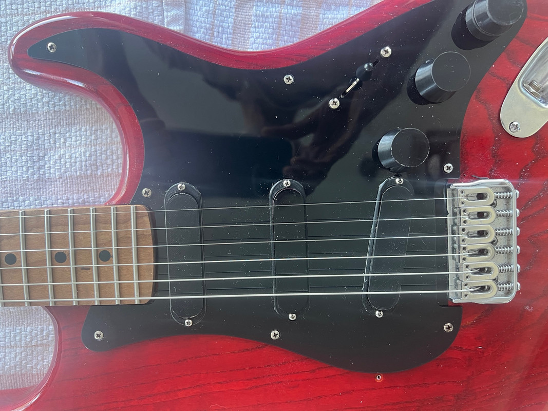
All three use #41 wire. @120 HZ: Inductance Resistance turns per coil Neck pickup: 2.49 H; 5.49 KOhms 4400 turns middle pickup: 2.79 H; 6.01 KOhms 4800 turns Bridge pickup 3.10 H; 6.41 KOhms 5100 turns On this guitar each pickup has its own tone control. (The dual shaft pot is like used on a Fender jazz bass. One element is 500K, the other 250K, but that works out OK.) I use pickup rings to help protect the windings. The Q is higher than standard, but this gives only a slightly brighter sound because the dominant damping in a strat is the circuit loading (volume control, tone control, and a lesser effect from the amp input impedance. This is well within the adjustment range of the tone controls, of course |
|
|
|
Post by ms on Feb 11, 2022 18:49:35 GMT -5
Innovative solution. So the Ferrite doesn't draw the opposing feilds down to create an area of cancellation in the middle? Suppose we have N against the face of the top coil, and S against the face of the bottom coil. The bottom coil is upside down, and so the field direction is continuous through the ferrite. This is the way I prefer to do it, but it works the other way too. This is because the field from the thin magnets decays quickly with distance, although the permeability of the ferrite extends it a bit. Remember, the purpose of the permanent field is to magnetize the strings, and we want to avoid "side effects", such as altering the permeability of the coil, or if we cannot avoid the effect, we want to cancel out its effect. |
|
|
|
Post by ms on Feb 7, 2022 18:38:48 GMT -5
Traditional materials limit the achievable performance of guitar pickups because you have to make tradeoffs among the various desirable properties. The family of pickups described in this discussion use non-traditional materials that allow a much better compromise. The technology and techniques used here allow the experienced hobbyist to make them. Fender’s construction techniques make it easy to swap or replace parts. But strat pickups are excessively narrow, constraining changes and improvements when leaving the body and pick guard in their original forms. They are noisy and low output, but have low inductance and losses, and so they have a frequency response that is very useful for some purposes. We want to make a more capable pickup for the strat and similar guitars that still fits into the pick guard and/or body rout. So we want a pickup that is hum bucking and has higher output than a traditional strat pickup, while maintaining the low inductance and low electrical losses (high Q) that enable the traditional sound. Also, we want the design of the core and bobbin to allow higher inductance (but not necessarily retaining such low losses) so that we can wind a pickup that sounds similar to a jazzmaster or P-90 pickup if we want. Why not expand the usefulness of the most available “parts” body to include all the most useful single coil pickup sounds in the same narrow format? By hum bucking we mean that it cancels hum from magnetic fields; this requires two coils, but we want string sampling like a single coil pickup in order avoid the filtering introduced by, for example, a Gibson type of side-by-side humbucker. Often a stacked design is implemented to make a hum bucking strat pickup since we have some extra space in depth but not width. So that is what we use in this design, using non-traditional materials to improve the efficiency of the magnetic circuit. The first picture shows the final prototype (meaning it is not in a guitar and can be photographed easily). The two coils are essentially identical except for connections; the bottom coil is flipped over so both coils mate with a ferrite cross piece (not visible, covered by plastic) that shortens flux return paths. With mounting in the middle and coils that are less deep than standard, the pickup can stick through the pick guard just enough. (For the strat I will show later, I use short tubing on the neck and middle pickup screws, but none on the bridge pickup, which is screwed directly to the pick guard).  Why improve the efficiency of the magnetic circuit? We have two coils instead of the single coil of a standard pickup, and so resistance and inductance might get too large. Also, although he depth of the pickup (one coil on top of the other) can be more than a standard pickup, we want to keep it less than twice. So the top coil, the signal sensor, must do more in less space, and the bottom coil should be the same thus, we need high sensitivity without making the inductance of each coil too high. This is not quite as hard as it might seem for two reasons. First, the turns near the bottom of a strat pickup contribute almost nothing to the output, but do contribute to the inductance, and so shortening the coil loses less output than you might expect, and lowers the inductance. Second, two coils phased for hum bucking in a stacked design have negative mutual inductance, and so we get less than twice the inductance of each coil when we put two in series, but we still need better magnetic material to get as much improvement as possible. So we use a material for the core with higher permeability than AlNiCo, but we cannot use steel because of the losses from eddy currents. So we need to use a ferrite, an electrical insulator, or near insulator, depending, with high permeability. Why don’t pickups in general uses ferrites for pole pieces? I think that the answer is that when decent quality ferrites became available in the 1960s, pickup design was already done, while some later “improvements” were just minor changes made to define a product. Also, really good magnets combined with ferrites make the full improvements possible. Such magnets did not become readily available until the 1980s. In this design tiny neo magnets are located on top of the ferrite, close to the strings, leaving as much room as possible for the ferrite and wire. This is useful. For example, we can use slightly larger wire so that the resistance of two coils in series is less than or equal to a standard strat pickup. I use #41 for inductances up to about 3.1 H, and 42 or 43 for higher inductance, lower Q pickups. The next attachment shows how to make a coil, and how to assemble and wire two coils. A cover is not used so that there is a bit more space for wire. The ferrite blade is thinner than the diameter of a pole piece, also leaving more space for wire. The two ferrite pieces are Amidoncorp.com part numbers DC-43-15A and DC-43-25A. The bobbins are made from a premium grade of PLA, produced on an inexpensive 3D printer. Super glue makes an extremely strong bond because it softens the surface somewhat, and so it should be applied to both surfaces before assembling them. Super glue also produces a strong bond between the pieces of ferrite, but only if they are extremely clean and the surfaces very flat. These pickups are not intended to be taken apart and repaired.  The magnets make a thin layer of magnetic material on top of the ferrite blade; that is, they are the closest element to the string. Since they are thin, the permanent field falls off quickly with distance. The field is stronger than A5 pole pieces when both are measured at the magnets, but a bit weaker at the distance I use them from the string. It is possible to adjust the field strength without changing the pickup height very much. I think I can hear a difference in the sound produced by the pickup with very small changes in the height, but I have made no serious attempt to verify this. Since the magnets have some (small) effect on the inductance (affecting core permeability), magnets are used in both the top and bottom coils to get the best match for hum bucking. If the top coil has north out of the closed face, then the bottom coil has south out of its closed face. Another reason for doing this is that there is almost no permanent field in the cross piece, assuring we have very pure single coil string sampling. I have put these pickups on two guitars; the next post will look some of the pickup characteristics. Later, a discussion will appear in the the testing and modeling sub-forum with some more detailed measurements made on a prototype. (Sometime I will clean up the freeCAD files and post them, along with the .stl files.) |
|
|
|
Post by ms on Jan 27, 2022 10:20:32 GMT -5
Consider one pole of a strat pickup with N facing upwards. The flux in the coil consists of the flux in the magnet going up and a smaller flux in the coil outside the magnet returning down. What happens if you introduce an unmagnetised string from infinity to the normal working position? The flux in the magnet increases and the returning flux decreases. There is a net gain in flux within the coil. The magnet flux increases because the space near to the magnet has a marginally lower reluctance than before so the mmf of the magnet can produce a larger flux. The return flux in the coil windings decreases because the return path including the string now has a slightly lower overall reluctance near the N pole. The lua program www.aquinaudio.co.uk/DD/plate.luawill run on any FEMM installation and illustrates this, albeit in 2D. Download and run from the bottom selection in the file menu of FEMM The results appear in the lua console which the program opens.
The plate mu is set at 10 so that it doesn't intercept too much flux. Perhaps 1.1 would better represent
the effect of a thin string. At 1.1 the increase in flux is still there but the change in the flux lines is no longer perceptible.
Yes, it runs as it should. The 5+% change in flux through the coil with a plate permeability of 10 is a bit more than I would have expected, even with a plate replacing the string, but I am sure that it is right. If you increase the plate permeability to 500, then you get a 15% change, and the plate becomes a really good magnetic shield with very low field above it. You can reduce the permeability in the y (vertical) direction to unity and still get a big effect, as one would expect from the plate geometry. What is the physical explanation? For that we have to drop a level below material permeability, which is a convenience introduced into the macroscopic Maxwell equations too allow easier mathematical solutions to problems involving magnetic materials. High permeability in a ferromagnetic material means that the tiny magnetic domains can be moved towards alignment with a small applied field. That is, it is easy to magnetize the material. Thus the physical explanation is that the system composed of magnet and plate reaches its lowest energy state when the plate becomes magnetized in such a way that the B field above the plate is almost canceled. |
|
|
|
Post by ms on Jan 27, 2022 5:51:26 GMT -5
The sensing width is somewhat wider than a pole diameter. I believe that Zollner shows this (https://www.gitec-forum-eng.de/the-book/). I am not sure that link gets you all the pdf files, but you can find them.
|
|
|
|
Post by ms on Jan 25, 2022 7:34:19 GMT -5
A point of view: while accepting the magnetised string pickup model, it is just a model. A guitar pickup is a hybrid of variable reluctance and moving magnet but for the sake of convenience it is useful to consider only the variable part of the flux and model it as a moving magnet system. If the string were made of a soft magnetic material, then the only magnetisation would be that immediately caused by its immersion in the static magnetic field. In this case we would have a pure variable reluctance pickup in which the string causes a flux change in the coil by variably re-routing a small part of the magnetic flux from the static field set up by the magnets. I think that there is a very real difference between variable reluctance and moving magnet. I do not think it has to do with whether we have a permanent magnet or not, but a lot to do with how much the flux changes around the whole path of the magnetic circuit. I think a variable reluctance system must use a "closed versus nearly closed" magnetic path with high permeability material to get enough reluctance change so that the dominant flux change through the sensing coil is the result of the flux change around the whole path. The magnetic circuit associated with the guitar pickup is nearly all high reluctance (or maybe I should say " high reluctivity" in analogy to "high resistivity"). Moving the string results in extremely little change in the field far from the string, while in a true variable reluctance system, the flux changes significantly around the whole path. |
|
|
|
Post by ms on Jan 25, 2022 7:05:12 GMT -5
The thing is that magnetic resistance happens just by having air gap, but with direct current and voltage the losses are minimal so long as the copper wires are all connected. When people think about direct current in wire, the air around the wire matters a whole lot less than air around a magnetic path. With a magnetic field, it extends though air, but when you snip a wire and create and air gap, the direct current stops flowing. There's capacitive coupling, but most people just think in terms of DC current and touching wires, imagining water in pipes. So then I suppose you have to talk about how the air in the magnetic field is like lots of resistors, and that gets more confusing than things have to be. I think that FEMM model is a good way to show someone how the string relates to the pole piece, for all the people who believe it's work is done once it magnetizes the guitar string. Yes, that is important. The ratio of high to low conductivity can be very high in typical problems, while the ratio of high to low permeability is not so high. This means that you must be very careful how you apply the analogy. It is easy to come to false conclusions. |
|
|
|
Post by ms on Jan 24, 2022 18:54:44 GMT -5
I think the reluctance model is useful when thinking about the relative voltage output of a single coil with steel poles versus AlNiCo, as was being talked about in the other ongoing thread.... The reluctance method depends on two things: 1. The same mathematical form applies to 1.) current density equals conductivity times E field and 2.) magnetic flux density (B) equals permeability times magnetic field (H). 2. The magnetic problem is equivalent to a network of resistors driven by a voltage. The first applies here, but the second does not. The plot below is of a tiny neo magnet (simulating the string, almost a simple dipole field) over a pole piece, showing two different permeabilities. It is in the cylindrical symmetry mode, and so the plots are of just the right half. When mu equals one, the pole piece does nothing. The flux falls off quickly as expected. Note that the flux is heavily clipped near the magnet; that is, we would need a lot more colors to show how strong it gets near the magnet. When mu = 500, it does not fall off so fast. So, do the plots look right for mentally replacing the small magnet with an electric dipole, replacing the spatial variation of permeability with conductivity, and getting current density instead of flux density? They do to me, and so this analogy helps me to decide that the Femm result is useful.  |
|
|
|
Post by ms on Jan 23, 2022 14:03:32 GMT -5
Hi aquin43. Another point of view: We have physics, and we have methods for solving physics problems. The physics is that the string becomes magnetized. This can be by one or more means, and the magnetization can change with time. The concept of variable reluctance is part of a method for solving certain simple problems involving magnetic materials. As you point out, it is not simple to apply to a guitar pickup. Thus the concept of variable reluctance is useful only as an analogy, not a method of solution. I think it is a dangerous analogy that can hide the physics.
|
|
|
|
Post by ms on Jan 23, 2022 9:42:25 GMT -5
Oh, I see. I was using the output of one coil as a reference. Series makes the output go up, doubling into an infinite load. Parallel with identical coils, sampling, and an infinite load should stay the same as a single coil. Parallel has lower impedance than single coil and therefore can drive a given load harder. Of course, the resonant frequency might be too high with parallel, putting the peak above the desired frequency/
|
|
|
|
Post by ms on Jan 22, 2022 12:04:25 GMT -5
The strength of the magnetic field affects the operating point on the hysteresis curve, and thus the permeability, and therefore the inductance and the resonant frequency. The Q is a function of the losses in the resonant circuit, and one factor in that is the conductivity of the pole material. But the Q has little to do directly with the permeability or the strength of the permanent field. Yes, the strength of the permanent field affects the relative levels of the string harmonics, and thus the frequency response of the instrument. (Here I am using "frequency response" in a more general way than just the response of the electronic filter made by the pickup circuit. Sorry if that is confusing.) More flux from the vibrating string through the core does not do that. (I do not think that Scott Lawing can give you a more definitive answer.) A stronger magnetic field affects how the string vibrates; that is the source of the change in harmonics. There is no analogous effect in the core. Check out his blog on pickup function. He specifically models the string flux line paths of an A5 vs higher permeability pole. There will simply be more V If more of the lines from the string pass though more of the coil. How is that controversial? I can't say if that will increase stronger vibrations more than weaker ones, but it sems like it might. Yes, there is more voltage when the relative permeability of the core increases from unity (more changing flux, more voltage: law of magnetic induction), although if you continue to increase the permeability, the increase slows down and stops. But you seem to be saying you think that when the permeability goes up the ratio of different harmonics might change. I do not think that this possible. Maybe I am misunderstanding what you mean? |
|
|
|
Post by ms on Jan 22, 2022 9:51:33 GMT -5
I am confused. If there is a significant difference in Q, you hear it. But why should there be very much difference in Q between A5 and A3? It is the conductivity of the material that matters for the Q, and I suspect that it is not all that different. I do not understand how drawing flux lines into the coil increases lower harmonic strength. Why should it have any effect on the frequency response? I think the Q of a coil is a bit lower with A2 or A3 than A5, but I don't know if permeability or Gauss is the cause. Again, the relative difference in the resonance peak is much less after it's damped by the total resistance load. It's not the freq response, but the relative difference of the stronger vs weaker string vibrations for each note that is accentuated by coil proximity. I'm speculating that roughly the same thing happens when the flux lines are pulled deeper into the coil, but it might just increase overall output for a given Gauss level. Scott Lawing might know a definitive answer. The strength of the magnetic field affects the operating point on the hysteresis curve, and thus the permeability, and therefore the inductance and the resonant frequency. The Q is a function of the losses in the resonant circuit, and one factor in that is the conductivity of the pole material. But the Q has little to do directly with the permeability or the strength of the permanent field. Yes, the strength of the permanent field affects the relative levels of the string harmonics, and thus the frequency response of the instrument. (Here I am using "frequency response" in a more general way than just the response of the electronic filter made by the pickup circuit. Sorry if that is confusing.) More flux from the vibrating string through the core does not do that. (I do not think that Scott Lawing can give you a more definitive answer.) A stronger magnetic field affects how the string vibrates; that is the source of the change in harmonics. There is no analogous effect in the core. |
|
|
|
Post by ms on Jan 22, 2022 7:17:19 GMT -5
Are you sure you have all that right? There is no doubt that a higher Q gives a brighter sound. I am not saying that a stronger field does not have do it, too by increasing harmonics. Lower permeability can lead to a brighter sound by lowering inductance and raising the resonant frequency. The Q makes much less difference when the total resistance on the pickup is factored in. There may then be less than 1dB difference in the peak of a coil going from A5 to A3, but less than half the Gauss has a big affect on how string pull affects the harmonics and how the attack hits the amp input stage. The higher permeability of A3 would only slightly increase inductance, but the affect of drawing the string flux lines down more into the coil is likely what increases lower harmonic strength. It should be akin to raising the coil closer to the string in a respect. I don't know if anyone has a definitive answer on that. I'd ask Scott. I am confused. If there is a significant difference in Q, you hear it. But why should there be very much difference in Q between A5 and A3? It is the conductivity of the material that matters for the Q, and I suspect that it is not all that different. I do not understand how drawing flux lines into the coil increases lower harmonic strength. Why should it have any effect on the frequency response? |
|
|
|
Post by ms on Jan 22, 2022 6:04:06 GMT -5
an offtopic question kind gentlemen as far as output goes parallel wiring should be like for example if humbucker in series is 16ohm parallel would be around 4 right? but that's not the only thing right (considering gauss, indurance, etc) ? so my question is does volume "technically" drops when in parallel mode ? or gainwise ? i know dumb question but ... it cuts the mids ... sounds more like p90ish like people say (never tried it myself in bridge position). well the thing is i don't like humbucker midrange at all ... so that's why i became curious about paf-ish pickups (i think lower output should push down mids a little) edit: p.s. i remember having phat cats with alnico 2 magnets ... and as i remember i hated the sound of a2 ... was too woobly, but in humbucker case my friend has gibson les paul 1960 traditional with '57 Classic Plus Pickups (a2) and that's the only les paul i like ... not a gibson guy by any means and i just found the very same donlis pickups with alnico 2 magnets ... so my another question is would it have less mids and more bottom end? by the way the model number and description is the same DHN22 which seems kinda shady but anyway here they are : www.aliexpress.com/item/32725181955.html?spm=a2g0o.store_pc_groupList.8148356.27.6ab470e8tqbl1PYeah in parallel, the output drops. The amount of voltage being produced by each coil is the same, in series it would add together, but in parallel, each coil acts as a load upon the other, dropping the overall voltage output. The funny consequence of that, is that whichever coil would be louder in series, due to having more turns of wire on it, becomes the quieter coil in parallel, because it's more loaded down by the quieter coil, than the quieter coil is of it. That's why parallel mode is about the same output as using any one of the coils alone. There's technically no mid scoop, the resonant peak just increase and adds more treble while also dropping in overall output, which people perceive as a drop in the mids. I don't think a humbucker in parallel sounds anything like P-90, they're not even technically similar. A P-90 has an inductance of around 7 henries, a parallel PAF around 2 henries, so they're on opposite ends of the spectrum. A P-90 sounds much fatter and thicker. Because a P-90 only has one coil and one row of pole pieces, it pickups up more harmonics than a PAF's two coils, and that lends it brightness a 7 henry PAF doesn't have (like a JB for example) but I don't think the tone is comparable. The P-90 picks up mids through physical means, where as a parallel PAF picks up treble through electrical means, and it's a different sound profile. If the two identical sources are put in parallel, the output should not drop. Into an infinite load, its should stay the same. When loaded, it should go up since a lower impedance source is driving the load. With hum bucking pickup coils it is a bit more complicated since they do not sample quite the same signal from the string, nor are they exactly identical. But I would not expect the output to drop much, if at all. |
|
|
|
Post by ms on Jan 22, 2022 5:56:54 GMT -5
You can find some examples of Bode plots plus a lot more relevant & accurate information from Dr. Scott Lawing on the Zexcoil site. FI, the magnetized string doesn't so much "excite" the magnetic field around the pickup as the flux lines coming from it simply oscillate through the coil. It's also not the sharper peak (higher Q) of AlNiCo V that makes it sound more snappy/brighter than AlNiCo II, III or IV, but the effect on the string harmonics from the stronger pull combined with how the lower permeability doesn't attract the flux lines as much into the coil. Scott covers all that and more in his Blog. Worth reading if you want the real story. Are you sure you have all that right? There is no doubt that a higher Q gives a brighter sound. I am not saying that a stronger field does not have do it, too by increasing harmonics. Lower permeability can lead to a brighter sound by lowering inductance and raising the resonant frequency. |
|
|
|
Post by ms on Jan 2, 2022 10:41:37 GMT -5
A regular humbucker does not reject electrical noise. You can think of this as a reversal of connections introducing two new paths which have opposite voltages across them.
How can an aluminum plate replace magnetic hum bucking? What are you trying to do with it?
If I were making a low impedance hum bucking balanced pickup, I would use a stacked or sidewinder design for single coil sampling, wind both coils with center taps, and connect the coils in parallel (so that both center taps can be grounded). Each coil should be twice the target impedance, and I would just accept some signal loss from paralleling the coils, counting this as part of the cost of obtaining very good cancellation of both magnetic and electric interference. No shielding should be necessary because of the good cancelation, but I would probably shield anyway because I think that the effect of eddy currents would be much reduced in a low impedance non-resonant design. To that end, I would make sure that the coil impedance is correct so that the load introduced by the mic input has sufficient damping so that there is no resonance peak.
|
|
|
|
Post by ms on Dec 31, 2021 19:55:05 GMT -5
The current Les Paul Recording guitar (http://legacy.gibson.com/Products/Electric-Guitars/Les-Paul/Gibson-USA/Les-Paul-Recording.aspx) uses a transformer to achieve "balanced" output at low impedance and also high impedance (presumably single ended). It is not clear whether the pickups are inherently high or low Z.
One relatively simple project would be to wind a balanced pickup that could drive a microphone input on your recording interface. Is this what you have in mind?
|
|


