|
|
Post by ms on May 16, 2024 10:46:53 GMT -5
I appreciate your help! I would probably assume he would drop in 500k. I wonder if I could put C5 or C8 magnets in place of those. Do you think the magnet would be strong enough to pick up through the case of the P-90 if I left off the cover of the mini? Could I fit the poles of the P-90 between the coils, for cosmetics, since these coils don't need to be connected by a single magnet below them like a standard humbucker or mini deluxe? You might lose output level with the C magnets, hard to say. The Alnico has low permeability but it is probably more than the ceramic. The permeability of magnets in the coil helps guide the flux from the vibrating strings through the coil, increasing output. I would stick with the A2. The stronger C might cause problems similar to a strat pickup too close to the strings; again, hard to say for sure. Stew mac says the output of their firebird kit is more than a standard minihumbucker. I am not convinced. Usually removing steel poles and slug decreases the output, but raises the resonant frequency and increases the Q. Fake pole pieces? Not for me, that's for sure. The P-90 cover is plastic. It spaces you down a bit, but it is not magnetic and does not alter the flux from the magnets going up to the strings, or the flux from the strings coming back down through the coil. |
|
|
|
Post by ms on May 16, 2024 10:23:27 GMT -5
This is really interesting work. The final result is like two strat pickups side by side but with the later half height coil to lower the inductance. How does the output level compare with a strat pickup? I ask because a further modification that comes to mind is to parallel the virtually identical coils so as to lower the output impedance, use 50k pots and become virtually independent of the cable loading.
Thanks! The output is significantly more than a strat pickup, but less than a normal humbucker, of course. As we know, the turns further from the strings contribute little output in a strat pickup, and so in this design the average turn is located closer to the strings. Also having two coils instead of one helps with the output/inductance ratio since inductance varies faster than linear with turn count. I have not made accurate inter-comparisons yet. It is probably not good enough for what you want to do, that is, keeping the output equal to a standard strat pickup with the coils in these pickups in parallel. I am setting up a guitar to allow better comparisons, but that is still somewhat in the future. That is, it is better to make comparisons of different pickups on the same guitar, but it would maybe still be useful to compare the output of a strat with a guitar with these modified humbuckers, but the with the coils in parallel. I was wrong; your idea will work really well. For one guitar in the comparison, I used the black guitar shown above. Since the modified Fleor pickups are four conductor plus shield, it was only necessary to remove the back control compartment cover and move a couple of wires to put the neck pickup coils in parallel. I did not change pots, so this is not a listening comparison, just a look at the picked level on the scope. The other guitar is this: 
It uses a good quality roasted maple neck and the $97 JD Moon poplar body. The pickups are Fleor kits. The guitar has hum canceling ferrite core coils under the pick guard. The picked outputs viewed on a scope are almost the same. I think the black guitar is possibly slightly higher in output, but it is too close to call for sure without a better comparison. Changing the pots to 50K would load it a bit, but this idea should work. Even if you lost a bit of level, the signal to electric field hum ratio would improve because of the lower impedance, and of course the humbuckers lower the magnetic hum by at least 35 db if carefully made. (Even the Fleor pickups do that well, well maybe not all of them.) And of course the change in tone with volume setting would be gone. |
|
|
|
Post by ms on May 15, 2024 14:20:43 GMT -5
This black guitar uses two modified FLEOR pickups, measurements shown below. At the time I ordered these, the only bobbin choice with the correct resistance coils (neck, 7 t08 K, and bridge, 8 to none K, was zebra. In the impedance figure below, the differences between the impedances of single coil sound and humbucker sound with respect to damping (or Q) are indicated. (Check the first post for measurements of humbuckers.)   As described here (https://guitarnuts2.proboards.com/thread/10727/pickup-imp-apparent-fall-rise) the curved shapes with frequency of the impedances (rising real, falling imaginary) are the result of resistance in parallel with the coil, the result of magnetic coupling to metal parts, primarily the pole pieces. There is a push-pull switch on each tone pot for the corresponding parallel capacitor. This guitar has 1000 pf on each switch. With both pickups on you can choose zero, one, or two capacitors.  |
|
|
|
Post by ms on May 15, 2024 11:10:27 GMT -5
This is really interesting work. The final result is like two strat pickups side by side but with the later half height coil to lower the inductance.
How does the output level compare with a strat pickup? I ask because a further modification that comes to mind is to parallel the virtually identical coils so as to lower the output impedance, use 50k pots and become virtually independent of the cable loading.
Thanks! The output is significantly more than a strat pickup, but less than a normal humbucker, of course. As we know, the turns further from the strings contribute little output in a strat pickup, and so in this design the average turn is located closer to the strings. Also having two coils instead of one helps with the output/inductance ratio since inductance varies faster than linear with turn count. I have not made accurate inter-comparisons yet. It is probably not good enough for what you want to do, that is, keeping the output equal to a standard strat pickup with the coils in these pickups in parallel. I am setting up a guitar to allow better comparisons, but that is still somewhat in the future. That is, it is better to make comparisons of different pickups on the same guitar, but it would maybe still be useful to compare the output of a strat with a guitar with these modified humbuckers, but the with the coils in parallel. |
|
|
|
Post by ms on May 10, 2024 17:05:19 GMT -5
If the bode plots are the same, given the same measurement conditions, then the inductances are probably pretty close. It is the upper coil that counts for signal output. The goal is not get any flux from the vibrating strings into the bottom coil because it is electrically out of phase and causes a loss in output. So if the "dummy coil" at best contributes no output but the total inductances of the P90 and P100 are the same, then we would expect the P100 to have less output. That might be why people think it sounds different.
|
|
|
|
Post by ms on May 10, 2024 7:00:18 GMT -5
The guitar in the photo uses the two pickups whose measurements are shown in the middle and bottom of the right hand column in the measurements shown in the first post. The neck pickup has 4250 turns of #42 per coil, while the bridge has 4934. (I think that strange number resulted from scaling up the inductance. It might as well be 5000.) 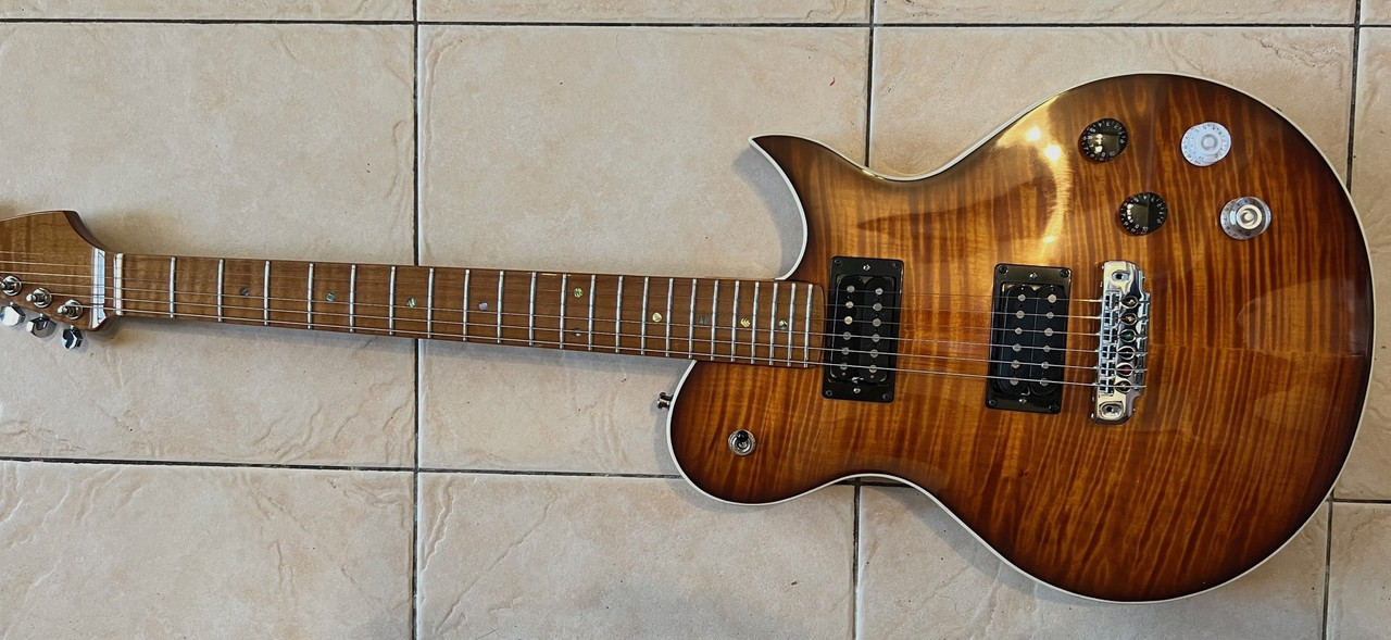
The wiring diagram is shown below. The volume pots are 250K, and I intended to use 250K for both of the tones pots, but I wanted a push-pull switch for paralleling additional capacitance across each pickup. So the neck pickup uses a so-called 500K pot that actually measures closer to 600K because that is all I had. I have not yet carefully listened to a set of capacitor values in order to select the optimum, but these are reasonable.  |
|
|
|
Post by ms on May 10, 2024 6:52:46 GMT -5
Thank you, I had read that post which is what made me consider sitting the bobbins on the side and magnetizing the poles using that. Would that work as I drew it? What would be the difference between that and sitting the bobbins upright? I was considering placing two mini humbucker bobbins with P-90 poles between them and a magnet beneath. How would that work? My main purpose is to make as simple of a humbucking pickup that will fit in a P-90 case, if possible with P-90 poles in the center, as possible. I agree with stratotarts post. As for putting the bobbins upright, both coils need their own poles or slug. It might be a bit of a mechanical mess, but I guess you could mount minihumbucker components into a P-90 case instead of the normal metal one, but there might be some issues getting to work out. Mini-HBs seem like a bunch of components stuffed into a cover. Edit: I forgot the lower diagram in your original post. The magnets would magnetize the slugs in the coils that would magnetize the screws that would magnetize the strings. I do not think you will get enough field to the strings. |
|
|
|
Post by ms on May 9, 2024 7:06:23 GMT -5
Here is a photo of a disassembled modified FLEOR showing the bottoms of the two coils. The two black 3D printed spacers fit over the rods and keep them slightly spaced from the baseplate or just touching it in some cases. I have not measured the electrical effect of the baseplate, but it must be small because the measurements in the previous post show low total loss, about what is expected from a single coil pickup using Alnico rods. (The coils are secured using the same screws that came with the pickup, but they are barely long enough, and it would be better to use longer ones.) The poles extend down different distances because I have staggered the pole pieces and have used two different lengths of rods (what I had). This particular one is a prototype and the pole pieces are not necessarily set to the proper heights. This is not the baseplate that came with the FLEOR, but those baseplates work fine, and I think I used the original one for something else. 
Edit: I forgot to mention that these pickups use A5 rods, but I have not fully magnetized them, keeping the field measured flush against the face to about 600 Gauss or a bit less. |
|
|
|
Post by ms on May 8, 2024 13:14:33 GMT -5
|
|
|
|
Post by ms on May 8, 2024 13:04:26 GMT -5
Here is part of a comment I made in guitarnuts2.proboards.com/thread/10690/humbucker-comb-filtering : "...you should get close to a tele lead or strat sound without the hum by making humbuckers in this way: 1. Use fewer turns on each coil so that the inductance of two in series is what you want. Since inductance decreases faster than linearly with turns, you do not need to take off that many. 2. Use Alnico rod magnets for the right Q. 3. Do not use a tall Bobbin; the turns near the bottom do not contribute much to the level. So the turns you lose with respect to a strat pickup to get the right inductance cost you less level than you might think in terms of output if you are used to strat pickups with tall bobbins. 4. Lose the baseplate? Not sure; a nickel silver base plate kills some highs, but not that much. The cores are more important." So a humbucker loses highs relative to a Fender type single coil as a result of the filtering effects of its electrical circuit (both higher inductance and higher losses, both largely from the permeability and conductivity of steel), and according to common belief, as a result of string filtering effects produced by the two spaced sampling regions. But it seems that the sampling issue really does not matter much, if at all. This is the result of the discussion referred to, and to some tests I did years ago. So this discussion shows that you can make humbuckers with single coil properties. First, why would you want to do this? A huge variety of guitars use original Gibson size humbuckers, but cannot be purchased with pickups that sound like Fender single coil, having both higher resonant frequency and lower loss (higher Q), and that reject magnetic hum. This discussion shows an easy pickup change that does all of this. Note that split coil with a normal humbucker only goes part way because of the steel cores, and loses hum cancelation. There are a few humbuckers available that use Alnico rods. For example, here is part of a description of a humbucker made by Dream Songs Pickups ( www.dreamsongspickups.com/en/content/strat-rod-magnets-humbucker) "...It is a beautiful sounding humbucker with rod magnets and it also has the sound of a true Stratocaster single coil in split mode. This pickup works well with 250k pots, but you may want to try it with 500k pots fot a clearer and grittier sound in humbucking mode. DCR from 10k to 12k ... " (I actually have some doubts about the claimed sound in split mode since this pickup is sold with a partial or complete metal cover, but I have never measured or heard one.) This is not the kind of pickup discussed here. This discussion is about humbucker pickups that have a single coil sound when used as a humbucker, but they also can have a humbucker sound (with less output than a typical humbucker) by adding parallel capacitance and possibly resistance. That is, single coil sound does not require just a single coil, but can be achieved by designing for the proper electrical properties, and, almost as important, humbucker sound is retained by further modifying the electrical properties. I have not found any such pickups for sale, but they are easy to make. Using Alnico rods results in less loss than steel, and less inductance, and so the required number of turns is similar to the minimum number used in available humbuckers. I have used two methods for making them: 1. Modify available humbucker bobbins, by drilling out the pole holes to fit available .195" Alnico rods, and wind with the required number of turns. (.187" rods might be easier to use; I have not tried these.) 2. Remove all the magnetic components and spacers from an available humbucker, modify the pole holes and install rods, using a custom made spacer so that standard rods can sit on top of the standard baseplate. The first method offers more flexibility, and it is easy to drill out standard bobbins made from high quality strong plastic with a 5 mm drill (followed by hand clean up). For the second method, very inexpensive FLEOR pickups can be used, selecting the lower resistance two options (not the overwound ones). Things to watch out for: 1. Although the two coils in a pickup are well matched, the resistance can vary up to 1K from pickup to pickup. 2. DO NOT DRILL OUT WITH POWER. The bobbins are made from very soft plastic. Drill out by hand only, (if you must use power, use a special bit designed for soft plastic and be very slow and careful). A standard bit grabs, and you can destroy the coil and injure yourself. It is not necessary to change the wiring at the pickup; in fact, it is not even necessary to disturb the tape around the two coils if you are careful. Standard rods extend well below the bottom of the bobbin (both types of implementation, of course), and so you need to make a special spacer. I print mine, but cutting wood or plastic should work well also. Somebody might sell a shorter rod that would work with standard spacers. So let's look at some measurements. These are impedance measurements, which are good at showing the location and width (losses or damping) of the peak and thus are good for comparing pickups and predicting the effects of a load. I display the magnitude of the impedance, which shows the peak, and the real and imaginary parts with the effect of pickup (and cable) capacitance removed. These days, I measure the capacitance with a meter at 100 KHz. This almost always gives a good enough value for the "unparalleling" computation. The attached plot has six measurements. The three in the left hand column are standard pickups, and the three in the right column are humbuckers intended to sound like single coils. The one in the upper left is a Fender single coil type that I wound from a kit. The other two in the left column are Seymour Duncan humbuckers. The three in the right column have single coil properties, and they sound like them, too. They are not identical to typical strat pickups, but they work just fine in that role. I have not yet made measurements with an exciter coil. It seems that the output level is between a normal single coil and a humbucker, but it would be good to know for sure. I have them in three guitars. Later posts will deal with wiring diagrams, etc., especially circuits to switch in typical humbucker sound. (In general, it is easier to lower a resonant frequency and increase damping, lower Q, than to go the other way, and so this is not so hard to do.)  |
|
|
|
Post by ms on May 6, 2024 13:50:06 GMT -5
Well, whether or not they are too powerful or not depends on what you want. I would expect them to be a bit brighter than the usual humbucker, but this could be exactly what you need with the 250K tone pots. The highs lost with the pots are not exactly as those gained with the magnets, and so he sound should be a bit different from other similar guitars.
|
|
|
|
Post by ms on May 6, 2024 13:40:15 GMT -5
The other thing of course is that the spacing between the pole pieces might be a bit larger, maybe 52 or 52.5mm instead of 50 from center of #1 to center of #6. This probably has little practical importance, although you might lose a bit more level than you expect when string bending #1.
|
|
|
|
Post by ms on May 2, 2024 6:03:48 GMT -5
With 250K tone pots the "ten" setting is the same as the half resistance setting when using 500K. (The corresponding number depends on the pot taper.) I guess heritage wanted to keep the full treble tone a bit more mellow than normal. This might also contribute to the smoothness of the control response that you noticed.
|
|
|
|
Post by ms on Apr 23, 2024 7:35:44 GMT -5
I think the chain of simple inductors, each with a parallel resistor, works so well because the first link of the chain, one inductor and one parallel resistor (and the coil resistance in series), is the exact solution when k, the coupling constant from the pickup coil to the "metal", is one. So even when k is not so high it is a good first step. Another way of looking at it uses a rearrangement of equation 7 from this: guitarnuts2.proboards.com/thread/8455/derivation-coupling-effectEquation 7: Z_p = j\omega L_c + R_c + \frac{\omega^2k^2L_c^2}{j\omega L_c + R_{se}}R_{se} is the resistance across the coil resulting from coupling to the "metal". Adding and subtracting k^2j\omega L_c gives: Z_p = k^2j\omega L_c + (1 - k^2)j\omega L_c + R_c + k^2\frac{\omega^2L_c^2}{j\omega L_c + R_{se}}Z_p = R_c + k^2\frac{j\omega L_c R_{se}}{j\omega L_c + R_{se}} + (1 - k^2)j\omega L_cSo the pickup impedance is the linear combination of two simple cases. The first simple case, when k = 1, is the coil resistance in series with the parallel combination of the coil inductance and the parallel resistance. (The fraction in the second term is of the form Z_AZ_B/(Z_A + Z_B).) The second simple case, when k = 0, is the coil resistance in series with the coil inductance. |
|
|
|
Post by ms on Apr 19, 2024 6:55:28 GMT -5
The green line in the first plot below shows the real part of the pickup impedance of an SD SH1N, with the effect of the coil capacitance removed. It rises with frequency as a result of eddy currents in metal parts, especially the cores. The magenta curve shows the imaginary part; its downward curve indicates an apparent fall in coil inductance with increasing frequency. Both of these effects can be the result of resistance in parallel with the coil, as we will see. In a pickup this can come from the mutual coupling to metal parts, which act like secondaries of a very poor transformer. The load from a transformer secondary appears in parallel with the primary. The effect of eddy currents has dependence on frequency; for example, the resistance must be infinity at DC.  Look at the impedance of a very simple model, shown below, just an L with both a series and parallel resistor (frequency independent). The colors match those in the plot above with values listed in the title. It is remarkable how close this is to the measurement above. It reproduces all the major features, but the shapes of the curves are not right. Next I will try to improve it, making the parallel resistance dependent on frequency (as we expect in the actual case).  |
|
|
|
Post by ms on Mar 16, 2024 17:57:34 GMT -5
Before proceeding, let's look at the test results from a humbucker, measured the same way as the pickup/cancellation coil. i went looking around for a humbucker, and the first one I found is a Seymour Duncan Jazz neck (SN2n). The first plot is the measurement from one coil. The second is for the two coils in series, that is, hum-canceled. The actual signal output is about 6 db more than that of one coil, and so six db must be added to the db differences on the two plots to get the degree of cancellation. The pickup parameters are 3.722 H, 7.21 K at 100 Hz. The individual coils are 1.6226 H at 3.54 K and 1.6208 H at 3.67 K. This is remarkably well matched in inductance, although this is achievable with careful turns counting. The resistance measurements are not so close since it is not possible to wind two coils in exactly the same way, even if the turns counts are the same. Also achieving such close inductances requires careful matching of the slugs and screws; that is materials and lengths must be carefully selected. So, given such good matching, how good is the cancellation?  
It looks like we have a bit less than 50 db of hum reduction at 170 Hz, and significant reduction over the whole useful signal bandwidth (about 5 KHz). A very well engineered and manufactured pickup! |
|
|
|
Post by ms on Mar 14, 2024 13:56:36 GMT -5
The wavelength dependency makes the frequencies inharmonic so that the overall shape of the composite wave changes with time. And non-linearity in the signal chain could make this important. |
|
|
|
Post by ms on Mar 14, 2024 13:54:48 GMT -5
If I understand this right, then you could argue that the steel pieces between the magnets guide flux from the vibrating string to the bottom of the extra deep bobbin. But it would appear that the sound of a humbucker is not strongly determined by the two sampling regions as the more than half century old pickup myth states. This paper seems to go into some detail on that question, but from what I can tell the aperture for single coil versus humbucker seems to be a bit of an assumption here? till.com/articles/PickupResponse/index.htmlRight, it is not the width of the pickup, as he says. But beyond that, whether the sampling window is 4 mm or 17 mm just does not make that much difference. Too much larger than that, though, and you will see a significant loss of higher harmonics, especially on E6. |
|
|
|
Post by ms on Mar 14, 2024 11:22:42 GMT -5
I looked some more and was able to find confirmation from PRS that the NF DD pickups do actually use magnetic pole pieces: "The new Narrowfield DD’s continue PRS’s proprietary Narrowfield pickup platform, but trade the Narrowfield’s traditional stairstep design for a mixed magnet/steel pole piece design and a slightly deeper bobbin" If I understand this right, then you could argue that the steel pieces between the magnets guide flux from the vibrating string to the bottom of the extra deep bobbin. But it would appear that the sound of a humbucker is not strongly determined by the two sampling regions as the more than half century old pickup myth states. |
|
|
|
Post by ms on Mar 14, 2024 11:14:43 GMT -5
On reflection, I think that the truth of the matter is that because the wave velocity increases with frequency, the wavelengths of the upper harmonics are not exact submultiples of the fundamental wavelength and don't fit exactly into the string length so the simple static pattern is never quite established until the upper harmonics have decayed.
The wavelengths of the harmonics are determined by the length of the string, and then the frequencies are a function of this length. You can measure the frequencies of the harmonics, and you will find that they are not exact multiples of the fundamental. Or, another way to say it: in the string vibration problem, the geometry of the system is input, and the frequencies of vibration are output. |
|
|
|
Post by ms on Mar 13, 2024 13:25:25 GMT -5
So here is the circuit from the previous post with the adjustment network in place. 
The first common sense thing to do is to get rid high frequencies from the cancellation coil that you do not need. Maybe they can cause trouble. Ch dos this; the value was chosen while recognizing that it might have some effect at frequencies we care about, but also recognizing that the other vales we choose will take the into account. The next thing to do is to get the low frequency cancellation working as well as possible with the resistor Ra. In this case the unadjusted correction voltage is a bit high, and so we a reduce it with one resistor. If it were a bit low, a slightly more complicated network would be necessary. The variable resistor for Ra is left in the circuit since a small readjustment might be necessary after the next step. It is surprising that even as low as 170 Hz there is a phase error. We know it is phase because we can measure the magnitudes of the pickup and cancellation coil voltages, noting that their difference is less than the measured residual. I suspect that this caused by eddy currents excited in the pole screws excited by the test B field. In any case Cp shifts the phase and improves the cancellation at 170 Hz. It also hurts the cancellation at higher frequencies, but this can be improved by Rs. |
|
|
|
Post by ms on Mar 12, 2024 13:42:47 GMT -5
So if you believe this test, (as I do), then you should get close to a tele lead or strat sound without the hum by making humbuckers in this way:
1. Use fewer turns on each coil so that the inductance of two in series is what you want. Since inductance decreases faster than linearly with turns, you do not need to take off that many.
2. Use Alnico rod magnets for the right Q.
3. Do not use a tall Bobbin; the turns near the bottom do not contribute much to the level. So the turns you lose with respect to a strat pickup to get the right inductance cost you less level than you might think in terms of output if you are used to strat pickups with tall bobbins.
4. Lose the baseplate? Not sure; a nickel silver base plate kills some highs, but not that much. The cores are more important.
Has anyone done something like this?
|
|
|
|
Post by ms on Mar 12, 2024 12:47:58 GMT -5
So now it is time to understand how a cancellation coil in series with a pickup works. I do not yet understand all the details, but enough to do a good job. The top part of the figure below illustrates a simplifying principle: if you only have impedances in series with the noise voltage sources, then achieving cancellation does not depend on what those impedances are or their relative values, nor on the load impedance. Of course, we want the impedances in series with the cancellation coil to be low value compared the in the pickup since we do not want to influence the sound. So what do you do if you have a coil capacitance that goes across the pickup, as shown in the bottom part of the figure? This is a situation where you can find the Thevenin equivalent, where for analysis, you replace the network you have with another that consists of a voltage source, Vth, that depends on the elements in the circuit, in series with an impedance, Zth, that also depends on the elements in the circuit. So then you have to find circuit element for the cancellation circuit such that when they are put in the circuit, its Thevenin equivalent voltage is the same as that of the pickup, that is, same magnitude versus frequency, but opposite phase. It is not assured that this is possible in all cases, but you certainly can do a good approximate job if you only need good results over a limited frequency range. In fact, you do not have to do any actual analysis. You can examine the circuit, do some arithmetic, and try things until you get something that works well enough. Later, we look at the result of this process.  |
|
|
|
Post by ms on Mar 12, 2024 12:20:15 GMT -5
Side note: Impedance is moot if you have an active preamplifier and a mixer for both the pickup and balance coil. Because then, there's no need to put them in series or parallel combination that would introduce the need for an undesired pickup impedance or some unwieldy passive compensation. Also the set input gain to the mixer, would dramatically loosen constraints on the balance coil.
I do fully understand the desire to avoid active electronics in a guitar.
I devised a "half active technique" quite a while ago, where the cancellation coil goes to the input of a source follower, and the pickups are removed from ground and connected to the output of the source follower. The cancellation coil is just another pickup, but you should make it very slightly more sensitive. I suppose that you could argue that once you have introduced active electronics into the guitar, you might as well go all the way put a preamp on the pickups as well. But you could also argue that the source follower can be low current for long battery life, and when the battery goes dead, the guitar still works, and all you lose is hum cancellation. |
|
|
|
Post by ms on Mar 12, 2024 11:45:28 GMT -5
The comb filtering due to adding two pickups is usually shown as continuing right up to the highest harmonics. The impulse response of such a filter would be two time spaced identical impulses for one input pulse. That may nearly be true for a humbucker pole spacing but we know that the travel of the wave on the string is dispersive, i.e. the impulse changes shape as it travels. So the two output pulses in the impulse response will have different shapes. The pure cancellation at short wavelengths seems unlikely.
Another factor I forgot about, if we're talking about higher frequency harmonics, they don't last long after the transient. So if you say the comb filtering only effects higher harmonics, then it will be limited to a "pick attack" modification of the sound. I think low harmonics are definitely filtered as the math describes, because you can fake the sound of "notch positions" with a graphic EQ by copying the comb filter, but not only that, if not for the comb filtering, the notch positions would sound more like a true blend of constituent pickup signals. I think he is saying that the comb filtering resulting from two pickups (say neck and bridge) works for low harmonics, but not for higher ones because of a kind of "blurring" resulting from dispersion. ("Blurring" might not be a great description, but it is all I can think of now.) But your decay time argument is right. At a high enough harmonic, or frequency, the pattern is never set up because the energy is gone before enough round trips can occur. But as long as the energy is there, I think it does. A given string harmonic corresponds to a very narrow frequency range, and so there is a well defined phase velocity. |
|
|
|
Post by ms on Mar 12, 2024 10:40:13 GMT -5
Since the result of this experiment is that there is an audible but not large effect, it proves the point even if the equivalence were not exact to the actual case. That is, it would be very hard to believe that some small difference between this test and the actual effect could make a large difference in the sound.
|
|
|
|
Post by ms on Mar 12, 2024 6:03:49 GMT -5
8 ==> 10
If the "in between" pieces are not magnetized, you need take into account the possibility of decrease in volume with string bends. So there might be more to the design than meets the eye. These are taller, thinner bobbins, and so I guess that you need lots of steel to make sure that the windings furthest from the strings are effective (unlike the Alnico in Fender SC, which allows field to escape).
|
|
|
|
Post by ms on Mar 9, 2024 15:45:50 GMT -5
The pure cancellation at short wavelengths seems unlikely. Yes, the instrument would be frustrating to play if that were so. Because of the fretting in different places, notes would have effectively arbitrary volume. I think it's reasonable to believe that the effect exists, but is diffuse due to the phase spreading that you mentioned. In other words, affects all notes almost equally (with a gradation from very low to very high). Tillman's diagrams show the behaviour of an extremely simplified mathematical model. The short wavelengths are a very small fraction of the energy of the string vibration. I do not think that they affect the perceived volume very much. I think that more rapid damping of the higher harmonics is a more important effect than dispersion. Yes, the higher harmonics are not exact multiples of the fundamental but they are not that much off. |
|
|
|
Post by ms on Mar 9, 2024 6:54:30 GMT -5
The comb filtering due to adding two pickups is usually shown as continuing right up to the highest harmonics. The impulse response of such a filter would be two time spaced identical impulses for one input pulse. That may nearly be true for a humbucker pole spacing but we know that the travel of the wave on the string is dispersive, i.e. the impulse changes shape as it travels. So the two output pulses in the impulse response will have different shapes. The pure cancellation at short wavelengths seems unlikely.
Some years ago I measured several db of comb depth on the E6 string with a humbucker. It is a difficult measurement. |
|
|
|
Post by ms on Mar 9, 2024 6:48:10 GMT -5
Could the Ilitch sized dummy coil be made a lot smaller with a high permeability ferrite core? The air core dummy with a lot impedance has to have a lot of area, but I'm thinking with a ferrite core, maybe if could be really small and still have low impedance. That is the question that I wanted to answer, and I will go into details later. But here is a summary: Ferrite sensing coils require a long thin piece of the material (such as a rod) to be very sensitive. Look at the ferrite antenna in an old AM radio if you have one lying around, or read that paper I referred to above. Here the length of the rod is restricted by the thickness of the guitar body. First consider a strat pickup, not very sensitive. You can wind enough wire on a rod short enough to fit in the guitar to cancel the hum but the inductance is too high. You can use multiple coils: if you cut the number of turns down by a factor of N (for example 2), then the inductance goes down by N^2 (for example 4) and if you put N (for example 2) of these in series, you have kept the sensitivity the same, but cut the inductance by a factor of N (for example 2). For a strat you need 4 or 5 coils. This works; I got a cheap "almost strat" body and mounted the coils in holes drilled under the pick guard. There is enough room since the control route is not nearly as big as the area of the pick guard. I also implemented the ferrite technique on a Warmoth soloist body by mounting four cols in the extra large control cavity, drilling the coil locations just a little bit deeper. (There are details I will cover later.) A P-90 pickup with the standard 10,000 turns is about 9 db more sensitive than a strat pickup. This would be too many coils, although if you really wanted to do it this way, I suppose you could. As difficult as the large flat air core coils are to work with, it is still the better way to go for a P-90. For example, it has lower inductance than so many of the small ferrite core coils in series. So the really brief answer is that Ilitch is right if you want a single technique that can be adapted to any pickup. |
|


