|
|
Post by sumgai on Jan 16, 2024 11:22:29 GMT -5
aikiharp , First,  to the NutzHouse!  Next, a slight correction to what Steve just said about where to post.... The Gallery is for images of your guitar itself, either as built by a manufacturer, or as you built it, or as a "work-in-progress" on its way to being finished, etc. It's not where we publish circuit diagrams, such as you've offered. (Quoting you: (happy to share that wiring diagram if desired).) Generally speaking, the place for diagrams is in the Guitar Wiring forum, but there is at least one exception. A completed, tested, and working diagram can go in the Guitar Schematics forum. Pretty much, a poster in that forum is not asking questions, they're simply presenting something that others can use. However, other posters with questions can start discussions in those threads just as easily as if the circuit diagram had been posted in Guitar Wiring. For questions about a diagram, completed or otherwise, it's probably best to use the Guitar Wiring forum. If one wishes to discuss tone controls specifically, then a partial diagram in this forum ( Tone Control Discussions) is also a good place to get answers. As you've no doubt seen already, there is a good mixture of both completed tone circuits that are thrown out there for use by other modders, and extensive discussions stemming from questions about such-and-such a circuit. HTH sumgai
|
|
|
|
Post by sumgai on Jan 10, 2024 20:40:45 GMT -5
xhrist, Yes, you are correct - put any coil-split switching before any pickup selection, individual pickup or some combination. In fact, the same goes for any phasing operation - put that switch arrangement before the pickup selector. And here I'm staying on-topic - I mean for you to include the series override switch as part of the pickup selector section. Simple diagram: pickup -> coil-split -> phase -> selector -> Master Vol/Tone controls -> output jack.
Where individual controls for each pickup are desired, use this one instead: pickup -> coil-split -> phase -> Individual Vol/Tone controls -> selector -> output jack.But for that latter arrangement, do pay attention to the discussion in the link provided by newey. We (the Nuts in the House) have been hashing this out for a long time, for various posters and discussions. The provided link sums up the whole ball of wax and simplifies it very nicely. But as usual, questions are free, no points will be deducted for asking for help.  HTH sumgai |
|
|
|
Post by sumgai on Jan 10, 2024 12:39:34 GMT -5
xhrist, First, to The NutzHouse! Second, you've over-thought how to achieve your goal, and needlessly complicated it - that resulted in something that I'm sure you won't want to take on stage. As newey explained, you will benefit from instituting a "series-override" setup. By that we mean, selecting series from a (single) switch will override whatever position the pickup selector is set to at the moment. Here's a diagram showing how to go from parallel to series-override: 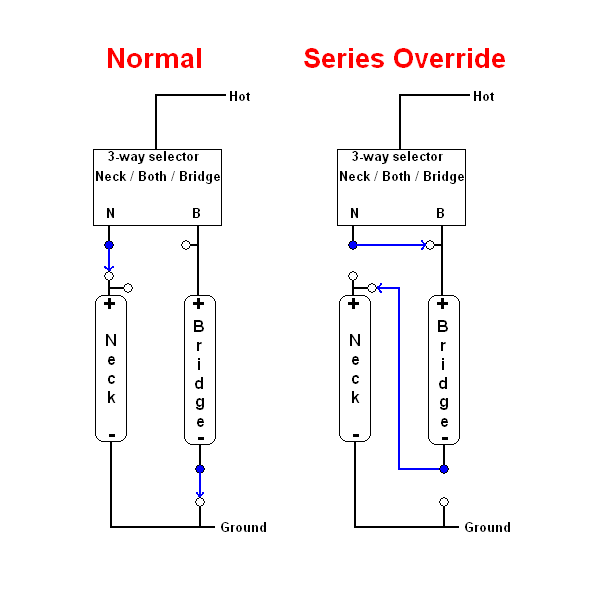 Now in your case, you have four pickups. Since you're not doing coil-splits, you can safely replace the humbucker design of two coils with just a single coil representation of your pickup... just like in the diagram above. (BTW, that image comes from a post by reTrEaD, back in 2018.) If you apply this arrangement to each pair of pickups, then apply it to the overall (final) selector switch, you'll have actually lowered the number of required switches to just six. There should be enough space in your control cavity for that, correct? If this wasn't clear, then don't hesitate to ask for help. HTH sumgai |
|
|
|
Post by sumgai on Jan 9, 2024 14:00:59 GMT -5
'master, Well, time for some semi-serious schooling. In short, if a pickup is not "loaded" (explanation in a moment), then it will sound out with all the treble it can possibly muster. Now a load is something that essentially 'resists' the pickup's efforts to produce all frequencies as loudly as it can. Your first encounter with a pickup-under-load is the two controls known as Volume and Tone - two pots present a load to the pickup, and the proof of this is that if you simply disconnect them, and run the pickup(s) straight to the amp, your tone will be more than a bit louder, and more than a bit treblier. So it stands to reason that putting a resistance (those pots) in parallel with the signal from the pickup will result in less trebles, right? That "resistance in parallel" doesn't have to be a pot, nor is it necessarily limited to just one or two resistances - you can put as much, or as little, load on that pickup 'hot' line as you wish. You may have read other threads here where we warn some folks about having all four pots (i.e. a 2V2T setup like a Les Paul, etc.) in the circuit at the same time. We're calling that a 'pretty hefty load on the tone', aren't we. Right about now, I'm sure you're putting two and two together and realizing that we're actually warning the modder about loss of tone, or more correctly, about loss of higher frequencies that are useful and in most cases, desirable. Now in your case, you still have too much treble. So it now also stands to reason that by merely introducing even more "load" into the circuit, you're going to knock down some of that shrillness. All of which is to say; Yes, you've interpreted me correctly: put an additional resistance from the incoming side of the Vol pot to ground, and see what happens to your tone. In some cases (dare I say, most cases), you'll want a value much higher than the Vol pot's value, because of Ohm's Law - resistances divide in parallel, they don't increase in parallel. In other cases, a value equal or even lower than that of the Vol pot may be needed. Which is why I said "be prepared to experiment", and why I volunteered the "bring wires outside of the control cavity for easy testing" method. (And yes, I know you have a Tele and could just leave the control plate hanging loose in order to switch things around, that last bit is for other readers with Strats and such.) Capice? HTH sumgai |
|
|
|
Post by sumgai on Jan 8, 2024 17:28:23 GMT -5
bm13, This is easy - simply hook up a fixed resistor from the Volume pot's hot (incoming) side to ground. In most Fender guitars, the Volume pot is 250K Ω, I'll assume your's is too. So a good starting point is a fixed resistor of the same value, 250K Ω. But here's a trick: in order to get the right value, don't solder it in just yet. Instead, use a pair of alligator clips and some wire to bring that resistor outside of the control cavity. Now you can experiment with different values until you find the one that works best for you. It may be higher or lower, be prepared to experiment for awhile. (In the alternative, you can just use another pot, and when you reach the magic spot, measure it with your multimeter. Fixed resistors can be found pretty close to your reading.) I'm sure you know what to do after this, right? HTH sumgai |
|
|
|
Post by sumgai on Jan 8, 2024 17:04:00 GMT -5
Bethany, I can appreciate your dilemma. But I do have to say, I also have a particular desire to be able to "fix" things as easily as possible, so I'm in the open frame camp. And I also admit that there are times, in certain builds, where a long barrel puts the terminals in a more friendly position for the builder, that's true. But in the long run, you may have overlooked why those luthiers are so adamant in their choice - it's spelled out pretty clearly - returns from customers due to faulty jacks. And this isn't necessarily due to the quality of the jack itself, but more likely the reason is ham-fisted players who don't know they're mistreating a rather more delicate part, compared to the tried-and-true Switchcraft open frame 1/4" audio jack. (Type 11 for mono (TS) or Type 12 for stereo (TRS)). As Amazon notes in a special box, pretty close to the top of the page, this part is one of their least returned items, people tend to have far fewer problems with it. But then again, perhaps that's where the quality comes into play, because it costs about twice as much as the knock-off's and wannabe's. HTH EDIT: And now you know why I outfit my guitars with RF cables! sumgai |
|
|
|
Post by sumgai on Jan 5, 2024 15:10:44 GMT -5
Steve, If you're not starting here: The Original Mike Richardson Strat Wiring Diagramthen you're banging your head against the wall, trying to reinvent the wheel. While Mike's diagram isn't exactly what you want, it's easy enough to figure out where to make the changes to fulfill your wish-list. HTH sumgai |
|
|
|
Post by sumgai on Jan 4, 2024 12:17:43 GMT -5
Sorry, for any concern I forwarded earlier, i should have investigated it at that point instead of passing what amounts to rumor or assumption (however good-intentioned that source was). Oh well, we know how the internet is (good and bad), and yet another reminder for the reason for supporting this forum, which a source of reason, empirical knowledge, help, and experience. No worries. Conversation is good. And informative conversation is even better. |
|
|
|
Post by sumgai on Jan 1, 2024 17:30:21 GMT -5
Bethany,
ChrisK would have only two words for you: MarketingSpeak Is.
He might also have gotten all wordy and said: Gefooey, or GelderFarb, or other similar dismissive phrases.
In short, all components have and can be made to exhibit, capacitance, inductance and resistance. Let me repeat that: ALL COMPONENTS, ACTIVE OR PASSIVE. The real test is whether or not such properties are measurable in some sense, in any given use case.
For our purposes, we can very safely ignore anything in the way of inductance in our capacitors. Worrying over such is folly, if for no other reason that any value of inductance we might find (which would require laboratory-grade test equipment) would be swamped by that of the pickup coils themselves, end of story. Even the cheapest capacitors we might purchase for installation will have a vanishingly small inductance value, compared to those coils.
Last Word: (paraphrasing ChrisK here) Someone is always the sucker. Make sure it's not you!
HTH
sumgai
|
|
|
|
Post by sumgai on Jan 1, 2024 15:31:24 GMT -5
I thought I remembered from the original star-point ground instructions, that it wasn't necessary to ground each pot to each other as shown on the diagram? There was some discussion about created a ground loop? Ground loops are not a 'thing' in ultra-low power circuits like we find in our guitars. The amount of resistance needed to introduce potential trouble spots is in the 10's or even 100's of Ohms, and we don't see that here. As much to the point, John Atchley's original GuitarNuts site espoused using just one connection between shield and signal for purposes of isolation between the user and the amp. But some contributors did note that this also reduces the chance of stray noise sources getting into the signal chain. As to segments, I wasn't speaking to multiple pieces of shielding, I just assumed that we are calling the shielding one segment that needs to be grounded at some point. The other segment is the signal return (or ground, if you must), that's where I get the two segments that need to be joined. In point of fact, ssstonelover's method is excellent. My only 'warning' is that it should be done on only one pot, not on more than one pot (or switch, what have you). It's not easy to spot, but in some cases, it's possible that a break exists between connections somewhere back up the line, and that might cause some kind of noticeable noise at the output. I can't guarantee that it 'will' cause noise, just that most of us have seen it happen at some point in our careers. It might not have happened to us personally, but if you've seen a guitarist on stage having a fit because of a small amount of noise out of her/his amp... that's a sign that something wasn't done with Best Practices in mind. reTrEaD correctly describes how to secure a wire to a contact point. Solder is meant to make a good mechanical connection an even stronger mechanical connection. At the power levels seen in the guitar, it should be possible to not use solder at all, trusting to strong mechanical connections to not come apart. But alas, that trust would be misplaced, for we've all seen, and perhaps personally experienced, wires coming loose faster than a speeding bullet. My method is to wrap all of the wires around the ring/connecting point first, and then solder everything all at the same time. There've been times when that wasn't possible, but about 98% of the time, it beats worrying about some previous connection coming loose, and having to re-do the thing. HTH sumgai |
|
|
|
Post by sumgai on Dec 30, 2023 20:16:43 GMT -5
Bethany,
Not a bad idea, but I do have to point out one thing: If this washer/ring is the only point of contact between the signal grounds and the Faraday cage, then all is well. For the rest of you reading this...
The whole point of the washer or ring is to isolate the signal grounds from the noise shielding (what is properly called a Faraday cage) for as long as possible. Of course, in order to get out of the guitar at the output jack, there will be a connection between the two. Best practice dictates that so long as there is only one point of contact, then we've done the best job possible.
What are the downfalls of multiple connections between the two segments? Not a lot, but then again, every so often a guitarist will find him/herself in a very noisy environment. That's when we come to appreciate the finer details of Best Practices like this. But yeah, probably most of the time, it won't make any noticeable difference in what comes out of your speaker(s) - good tone, or buzz/hum/squealing/radio stations/etc.
Or as ChrisK might've said: "Why do it wrong the first time when you could just as easily do it correctly when everything's all opened up. Or do you really enjoy doing it a second time, upon finding out the hard way that your laziness just cost you another trip to the workbench?"
HTH
sumgai
|
|
|
|
Post by sumgai on Dec 30, 2023 20:00:02 GMT -5
... but there is no change in tone on the push push tone pot which otherwise works fine (i.e. the push-push control works fine) I'm having a little trouble parsing that sentence. All I can come up with is that if the p/p switch works fine, that leads me to believe that there is supposed to be no change in tone. But if there is supposed be a tonal change, then the p/p switch is not working fine. Which way should I jump, bluesman13  BTW, a truth table for that diagram would be nice (for both the pup selector and the p/p). My first impression is that somebody dropped a tab of acid, then commenced to molesting a poor innocent sheet of paper. IOW, deucedly little makes any sense to me, I need clarification here.  If you please, of course. sumgai |
|
|
|
Post by sumgai on Dec 29, 2023 21:17:30 GMT -5
All of the above is why I use an RF cable. 'Nuff said.
|
|
|
|
Post by sumgai on Dec 25, 2023 2:22:54 GMT -5
Yeah, I went and searched for the oldest Christmas thread we had, just so I could append to it this little bon mot: sumgai |
|
|
|
Post by sumgai on Dec 22, 2023 0:50:30 GMT -5
Please choose from the following according to your preference: I'll take what's behind Door #1, Monty! Thanks, and the same to you as well. sumgai |
|
|
|
Post by sumgai on Dec 21, 2023 16:46:42 GMT -5
"Mass-produced" seems to have become a bad thing in people's minds, which confounds me. Same thing as 'cotton covered wire' or Orange Drop capacitors, etc. etc. It goes beyond confirmation bias and even beyond hero-worship (he plays a Les Paul, so I gotta play one too), it's simply Good Marketing Speak to beat the drum of "Keep Up With The Joneses", implying that "You'll never sound as good, nor play as good as your Hero if you aren't using our SuperDuperStudMaster device". No one has ever wondered why Marketing majors hate me so much. HTH sumgai |
|
|
|
Post by sumgai on Dec 5, 2023 15:34:01 GMT -5
Hoo boy where to begin, where to begin.
OK, my memory of history is not littered with definitive facts today, I'm only all about a general abstraction. Any of you can look up and corroborate, or argue against, what I'm about to espouse, that's all on you.
In history, Ampeg was actually the first amp maker to devise a circuit that imitated a Leslie effect. Fender did so a few years later, but Leo's circuit was a bastardization of his "Vibrato", and he was roundly called out for it. That was in the mid-to-late fifties, IIRC.
In the instance at bar, we're seeing a simplified version of the above, where two sources are combined in an orderly fashion to derive a new tonal palette. However, as noted, the waveform used to switch between the sources is now a square wave, and not the traditional triangle (or sometimes a sawtooth) waveform. This will cause a rather jarring effect insofar as what you hear. Will such be pleasing to the ear, or otherwise, that's the magic question.
And in the end of all things, a square wave is not analog, it's digital - that's the definition accepted in most engineering circles I've ever attended. Which is to say, it's only a control signal, imposed upon an analog signal. The final result is still analog through and through, but the modification to it along the way, that's what makes things interesting.... or distasteful, that's up to the listener.
I've heard a lot, in my time, about supercapacitors. Space-age stuff. Will it work here? Perhaps that's the reason for the high cost, who knows. But for me, the indicator is always the length of time any warranty or guarantee expires. If it's good for only a short period (less than one year is my baseline), then the company flat-out expects the thing to die an early death. Here's one of the few instances where a high price might be justified by a much longer warranty period - the company doesn't expect the thing to go kerblooey any time soon.
Food for thought, that's all.
[/daily core dump]
HTH
sumgai
|
|
|
|
Post by sumgai on Dec 5, 2023 14:53:54 GMT -5
I really want to find a 3/8” version. I hate to sound stupid, but what's a "3/8" version"? Length of the shaft? Length of the bushing? Diameter of the bushing? Depth of the terminal deck? Inquiring minds wish to know. sumgai |
|
|
|
Post by sumgai on Dec 4, 2023 23:34:07 GMT -5
That's not a pot, that's a switch, rotary style. You might try Mouser, Digikey or Newark, they're the go-to industrial supply houses for this kind of thing. However, Amazon, Alibaba and eBay all have many examples of what you're asking for, they're worth a look-see. General Guitar Gadgets has something you might like, and at a friendly price, go here. Other guitar parts outfits may also have something, but with the exception of General Guitar Gadgets, I didn't see anything that was PCB ready. As you've already guessed, many factors must be considered when choosing components, and these are no exception. I'd give a serious look at the GGG part, at first glance it has potential. Best I could do for ya on short notice. HTH sumgai |
|
|
|
Post by sumgai on Nov 28, 2023 13:09:45 GMT -5
I like to think that we (well, reTrEaD) did a lot of work devising keywords for those collapsed headers. Most of this site's design (i.e. what the user sees) falls to reTrEaD and YogiB, the rest of us have taken a "I approve" or at worst, a "I think...." approach to their works. With that said, we've had virtually no complaints from anyone since the inception of the 'new' first-time-arrival page. Not to say that you, col, are complaining, but if no one else has mentioned it in all that time... I'm somewhat 'forced' to believe that first-time newbies are not put off upon arrival to said page. Or at least they're willing to give it a try, and that's all we ask for, here in The NutzHouse.  Furthermore; Either reTrEaD has been reading Search Engine Optimation Weekly, or else he's pretty astute all on his own. But here's something that no one's mentioned yet, and that is that in 'any' search engine operation (hereinafter styled as SE) there are not one but two algorithms going on. One is to categorize whatever is found by the search bots, and the other is to interpret what a query is actually asking, in human terms. IOW, what matches the requester's human thought processes, not what seems to be the most popular result from similar word searches. Further IOW, it's all about the context, and that's where SE's precipitate out the wannabe's to the bottom of the beaker, leaving the good ones at the top. It is my experience that number of times you have to click through links is not germane to an SE, it's where the links point to that counts. We all tend to forget that a search bot is not a human, and doesn't have to be. As reTrEaD points out, bots don't care about appearances, they only care about destinations, and the contents found thereupon. This is where SEO comes in, and where SEO/algorithm defeating spam-bots come in as well. Appearance-to-humans aside, it's an all-out war, and I don't foresee any end to it within my lifetime. Not even a truce, for any reason.  More than three quarters of a century that I've been here, and so far the only change I've seen is how evolving technology simply shifts the focus on how Man continues to perpetrate inhumanity upon Man. As a famous bassplayer once said " Some people's kids!". HTH sumgai |
|
|
|
Post by sumgai on Nov 27, 2023 23:53:52 GMT -5
frets, unreg's correct, you've got to (gently) pin this guy down for a more specific meaning of "ground goes to....". But perhaps with pictures we'll see what's what. sumgai
|
|
|
|
Post by sumgai on Nov 26, 2023 18:56:03 GMT -5
OK, they're his pickups, and the pickups themselves are most likely the problem. Let's go down a standard troubleshooting path, shall we? As noted by mikecg, start with the environment. The easiest thing to do is move to another location. Best is another house, or at least somewhere that the same circuit is not in use. Another room might be OK, if it's on a different circuit... but that's still not as good as going elsewhere. A friend's home, a local pub or coffee house, even just outdoors, all are better than another room in the same house. An alternative would to bring another guitar into the equation. Either the customer has another axe to test with, or else a buddy should bring his guitar over and test with the same cable and same amp, in the exact same setting (position in the room, knobs dialed in the same way, etc.). This is also cheap, but guitar-playing friends might be unavailable for this purpose in a reasonable time frame - we all know how this goes. Next step: Test the pickups all by themselves. This means removing your control harness and just plugging the pickups straight into the amp. Much more difficult, and not a one-minute task, but at least it's still cheap. At this point, either the problem persists, and it's the pickups, or else the pups make no noise when "out of the guitar", and that means that he has a bad wiring job. And here, I'm presuming that you test everything before it leaves your factory, am I not correct? Conversely, have him hook your control harness to another set of pickups and see what happens. This just about covers all the bases. What we've done here was to implement the old Rule Number One of troubleshooting - Substitute With A Known Good Part. Not always the easiest or cheapest way, but when done in a logical manner, it gets the job done. It still could be other stuff, once we've eliminated the easy things. The body itself may have a resonance, but that's highly unlikely to affect both pickups. The body may have a shielded cavity, and somehow a short is occurring after his final assembly. Again, very unlikely, but we all know how Mr. Murphy works, don't we. If he hasn't sorted it out in a day or two, we'll need to see pictures. HTH sumgai |
|
|
|
Post by sumgai on Nov 26, 2023 12:09:02 GMT -5
Web crawling depends on who's doing the crawl operation. Some, such as Google, go as deep as they can find (valid) links, others perhaps not so deep.
I'm not concerned, as we have a not-indecent percentage of visitors brought to us by a search engine, looking for something specific, and the engine sent them here. From that I deduce that the engine was able to traipse down through top-level page and divine whatever was here that the requester was looking for. And sent them straight to that page, not to just the top level.
In fact, most sites that are essentially bulletin boards like ours do indeed have a 'full' top-level entry page that is fully expanded compared to ours. But I know people who are easily confused by such 'busy' pages, they prefer a more simple layout that they don't feel 'rushed' to absorb a bunch of stuff they don't necessarily want to bother with. For those kinds of folks, our home page is well-suited.
IOW, damned if we do, and damned if we don't - Hobb's Choice and all that.
HTHe
sumgai
p.s. Hey col, long time no hear from! How's your end of the world holding up?
|
|
|
|
Post by sumgai on Nov 25, 2023 23:45:58 GMT -5
I'm going to assume that you meant positions 2 and 3 are problem-free, and 1 and 4 (the single pups by themselves) are where the problem occurs, yes?
Is this customer playing with any additional effects pedals, such as perhaps a gain or a boost of some kind? Or is he getting this while playing straight to the amp?
When you say "my harness", are you including the pickups with that, or is the wiring harness made up of controls only, meant to be installed with pickups he obtained from elsewhere? Reason I ask is it sounds like the pups are slightly microphonic, where touching them sets them off, so to speak. (Provided he's not using some kind of effects pedal between the guitar and amp.)
HTH
sumgai
|
|
|
|
Post by sumgai on Nov 13, 2023 0:09:31 GMT -5
That said, I'm fairly certain that the two versions have different pickups, if for no other reason than the staggered pole heights would be different for left versus right. Probably not. This is a Tele, not a Strat. I've seen many "stock" Teles that had symmetrical pole height across the arc, no small percentage of 'flat' ones, and probably as many others that were staggered for 'string balance'. And the after market units, oh boy! A veritable smorgasbord of possibilities, to be sure. While I'm not so sure that a desk-drone did the LH diagram, your question about where the document might've originated set my nose to twitching - what if all 6 pages were actually made overseas? From an abbreviated set of 'Engineer's Notes'? I could see that happening, with the results that bluesman13 reported. sumgai |
|
|
|
Post by sumgai on Nov 12, 2023 23:48:15 GMT -5
It took awhile, but I finally doped out what that push-push switch is doing.... or alleged to do. It's a series override for Pos 2 - down is normal (parallel) and up is series. However, I'm not so sure that this is happening on the LH model, the diagram definitely is not easy to decipher!  And yes, I saw the 'solder lump' on the switch, with no wire going anywhere near it. This is indeed why I'm not certain that the series switch will work like it does in the RH model. All of which just goes to prove what we say here in The NutzHouse - a schematic divorces the physical from the theoretical. This means that one can design a logical diagram with one or more goals in mind, and do so without having to worry about where things will be mounted in the physical guitar. Doing it the other way around (making a wiring diagram without benefit of making up a schematic first) is tantamount to decorating a home before the house is even built! 'Nuff said. HTH sumgai |
|
|
|
Post by sumgai on Nov 12, 2023 11:51:24 GMT -5
bluesman13 , Wiring colors are a matter of preference and convention, they aren't mandated by some higher authority... much to the dismay of the guitar-modding community, I assure you. That said, I'm fairly certain that the two versions have different pickups, if for no other reason than the staggered pole heights would be different for left versus right. So why would Fender change colors for one pickup, but not the other? Good question. You might want to ask them about that.... All I can say is that the different dates between the two drawings, about 17 months, indicates the possibility that two different people created them. Could it be that someone wasn't paying attention when making the second version? I dunno. HTH sumgai
|
|
|
|
Post by sumgai on Nov 11, 2023 22:53:22 GMT -5
stevewf , The orange network is the source for both the vol and tone pots. It was the coloring that did it for me! You're correct, and I was wasn't. Your latest diagram from Post #14 should go directly into the Guitar Schematics sub-Forum! (And any wiring diagram you might later post.) sumgai
|
|
|
|
Post by sumgai on Nov 10, 2023 22:31:28 GMT -5
Starting a new project Tele (2 single coils) and wanted to know if it's possible to get the following options on a 5 way switch (or super switch, or with push pulls).
position 1 -- 50s "dark circuit" neck only w/ .047 cap (no tone control)
position 2 -- neck only position 3 -- neck and bridge in parallel position 4 -- neck and bridge in series position 5 -- bridge only us Those are just the ideal positions. This is doable, with minimal fuss. More in a moment stevewf has given you a start, but do note my message above regarding my concerns. Still, it's a good start, and easily fixed. Now, let's examine your first proposal. It's actually nothing more than a combination of the very first Fender Esquire (nee Broadcaster), and a current Baja Telecaster. The former had a Tone control bypass (for full dark) and the latter has all four possible combos (without any out-of-phase stuff). Since you don't mention OoP, I won't go into that just now. So what you can do, depending on how you like to "operate" your rig, is you can keep the blade switch 'normal' (5 positions) or normal for a Baja Tele (4 positions) and then use one or more mini-toggle switches to give more options. It will all depend on how much you interact with the controls while playing, especially while on stage, in front of people. (What some of us call "the fiddly factor", whereby the risk of something going wrong increases dramatically.) If you wish, I can whip up a diagram that will meet your first proposal, dead on. But as is the usual case here in The NutzHouse, you are not limited in any way against changing your mind! This happens all the time. So your biggest thing to consider is the ease of switching between sounds. After that, you might set a priority on parts, i.e. what you have on hand versus spending more cash for additional stuff. The ball's in your court partner, what's on your mind? HTH sumgai |
|
|
|
Post by sumgai on Nov 10, 2023 22:12:50 GMT -5
stevewf , I see a couple of potential problems here: a) You've set the Tone control after the Volume control. I'm pretty sure you're familiar with what that does to the interaction between the two controls, yes? Meaning, there's a reason why we set the Tone control(s) before the Volume control. and; b) When capacitors are hooked in series, the total capacitance is lower than either unit, not higher. Therefore, it won't matter which of C2 or C3 is smaller, that's the one that will dominate the tonality. Let me suggest that you either lash up a SPICE emulation, or drag out John's inimitable GutarFreak, and watch what happens with two caps in series. HTH sumgai
|
|


 to the NutzHouse!


