|
|
Post by sumgai on Aug 23, 2023 1:37:32 GMT -5
Vince, OK, that's close, but there are two flaws, one minor and one major. The minor one is that the upper tone control for the Lead section says "Mid" but it's wired for the Neck, just as you requested, and as I drew it. Your wiring is correct for your initial request, it's only the label that's bogus. Second, all three tone control caps are going from their respective terminals to the pot's shell and that's OK. However, you also show the same terminal(s) as going directly to ground, and that's not good - those controls are now nearly switch-like volume controls. In my drawing, the caps go between the terminal(s) and ground. Since the shell is effectively ground, just remove the extra ground wires from those terminals. Make those changes, and you're good to go.  HTH sumgai |
|
|
|
Post by sumgai on Aug 22, 2023 11:52:39 GMT -5
Vince,
Sorry, but even though you used the word "schematics", as in plural, there is only one schematic shown, and it's only half of the entirety. Until I can see all of the circuitry, I can't even do a triage, let alone a diagnosis.
But I will say that when it comes to loud extemporaneous popping sounds, the usual culprit is either a poor soldering job on the power supply filter capacitors, or those caps themselves showing a very short remaining life expectancy.
Let me not comment any further until the remaining diagram shows up.
HTH
sumgai
|
|
|
|
Post by sumgai on Aug 21, 2023 0:25:42 GMT -5
vince As others here will confirm, I am sometimes 'not all there' in my head. I won't elaborate. Your efforts so far, per your posted image, look to me like you've gotten some of the wires out of place. But don't tear everything out just yet, look at this updated diagram and take your time checking each wire's path from starting point to the other end. Here, I'm speaking specifically to your wiring around the Rhythm Tone control. There is also a problem with that Rhythm/Lead switch going to the Bridge pup.....  Like I said, double-check your work as you go. Another piece of advice might be to enlist a second pair of eyes. On occasion, it happens that one becomes convinced that something is correct when it's not - they're too familiar with the project. A second opinion often reveals the problem. I've now included all of the ground connections, in orange. I've also double-checked against several other diagrams, just to be sure I've got it correct. It all should work as you asked for in your "wish list".  HTH Oh, and apologies for the delay, This time it was my fault, not that of the Other Half.  sumgai |
|
|
|
Post by sumgai on Aug 17, 2023 0:52:02 GMT -5
.... or does he?
|
|
|
|
Post by sumgai on Aug 16, 2023 18:01:01 GMT -5
Nutz, if one or more of the pots were non-grounded in order to avoid the loading, could it be effective, and would it cause problems other than that loading? Yes, there will be problems. Without going into all the hoorah and hubbub, what the user sees as a result of using only two terminals is almost no change in volume for a large portion of rotation, and a drastically large change over a very small part of the rotation. What will also change as the pot is rotated is the tonality. Compared to the volume level, this is a non-problem. That is, unless the Woman Tone® is desired.  HTH sumgai |
|
|
|
Post by sumgai on Aug 15, 2023 13:57:23 GMT -5
Christof, First, Hi, and  to The NutzHouse! Let's get back to the basics here. Does your customer intend to have series combinations only, or does he/she want to be able to have parallel combos as wells as series combos? In another thread, I've outlined almost exactly what would work well for you, should you decide to 'dial back' to 2 tone controls (and the master volume). In that one, the posting member ( vince20) wants the Middle and Bridge to be controlled by a single tone knob. Where I went 'sideways' was to use the three DPDT slide switches found in his Jaguar to implement the third (newly installed Middle) pup, yet I was able to isolate them such that when either the Mid or the Bridge is selected alone, the other is not in the circuit. This can be a problem that stumps many a modder, until they start thinking outside of the box. As with newey's point above, when both tone controls are in the circuit (via the selection of Neck + Mid or Neck + Bridge), the sound (tone) can become a bit less 'bright'. This is an interaction that can't be avoided, short of kitwin's suggestion of active circuitry. But first we need an answer to my question above, what about series versus parallel, etc. HTH sumgai |
|
|
|
Post by sumgai on Aug 11, 2023 19:00:07 GMT -5
sumgai, did you not read this thread: Nope, sorry, I definitely missed that one. I just checked, and sure enough, I participated at the beginning, then fell off the back end. Hope I didn't hurt my head....  Damn I hate getting old. I wonder how many other statements I've made, and didn't follow-up on. Or even worse, how many promises have I made, and then completely forgotten to deliver on...... sumgai |
|
|
|
Post by sumgai on Aug 11, 2023 12:06:39 GMT -5
Can't speak for gumbo , but logistics are tough when you live where everything is upside down.  Wearing shoes during your next opportunity to play guitar, outside, shirtless in the snow might help you with logistics. Your feet are important. His feet are covered by what looks like snow - how do you know that he wasn't wearing some kind of foot gear? I need not say any more. sumgai |
|
|
|
Post by sumgai on Aug 10, 2023 10:34:14 GMT -5
Vince, The wife has (as usual) put the arm on my time for today. I'll try to get to this tonight, bot no hard-and-fast promises!  First glance: The Rhythm/Lead switch is 'upside-down', at least it's not oriented in the normal, expected fashion. If you want it that way, that's OK, it's your rig. Just thought I'd point it out, in case..... (To orient it the 'normal' way, just physically remove it and rotate it 180 degrees, then screw it back down tight. If the two green wires are too short, simply cut the cable tie, and put a new one on afterwards.) HTH sumgai |
|
|
|
Post by sumgai on Aug 7, 2023 17:09:06 GMT -5
^^^ Or they'll do a timed release, just like Hollywood does with moves and recordings. That way they get a better sense of how much needs to go where and when. Logistics is often the killer of innovation - just ask gumbo.  sumgai |
|
|
|
Post by sumgai on Aug 7, 2023 10:33:24 GMT -5
Ya know.... I use a CNC machine almost every day, cranking out quilts of all sizes. Now I could do that quilting by hand, but I'd like to finish just one, before I die. IOW, hand quilting is very time consuming, and fraught with potential errors. The QA process is almost as long as the actual stitching, because invariably you find small errors... but not so small that someone else (like perhaps the quilt's owner) won't find them! So instead I use a machine. A big one. A big computerized machine. And now I need only mount the parts and pieces, program the machine with a selected design, and let 'er rip. By hand? Indirectly, that's true, because I make all of the decisions, the machine (computer) only carries them out - no 'AI' involved anywhere along the line. As newey said, flawlessly, and repeatably if so desired. My QA time is shortened to minutes instead of hours, and usually turns up nothing to worry about. Yes there are occasional errors, but they're glaring, and with one or two exceptions, they're easy to fix. So, am I a "hand quilter"? No, but nonetheless I am a quilter who just happens to use an 'automated needle', which I prefer to think of it as my hand being on steroids, that's all OTOH, I suppose one could think that I'm now using my brains instead of my hands, but that would imply I'm working smarter, not harder. For Earthquaker, one probably should bet on the 'work smarter' aspect of their operations. HTH sumgai |
|
|
|
Post by sumgai on Aug 5, 2023 21:00:37 GMT -5
Very impressive, newey, kudos for the photos. Too bad they had to admit buyers to the toy-house in a 'take-a-ticket' manner, but like you said, they're close by. Should you suddenly feel the need, of course. sumgai |
|
|
|
Post by sumgai on Aug 3, 2023 15:53:09 GMT -5
geo,
The short answer to your query is that, yes, it's safe to plug things in like you decribe.
Where you'll find that the results are not what you wish is as newey describes - impedance mismatch. But will such a thing cause damage? Nope. Unless we're speaking about amplifier outputs greater than a watt or two, then impedance mismatches only create horrible sounding results.
Usually, and this isn't always true but usually, one wishes to feed low impedance into high impedance. For that reason, most devices have low impedance output (particularly headphone jacks), and most devices have high impedance inputs, on the order of several hundred Ohms, and as high as 100KΩ. Guitar pickups are often the exception here, a nominal "standard" single coil can run from 4KΩ to 15KΩ, and a few humbuckers have gone even highers. So amp inputs are often rated at greater than 50KΩ, and sometimes run to double that figure.
Likewise, pedals are built to roughly those same standards - high input impedance, low output impedance. So again, you won't damage anything (except possibly your sanity) by hooking things up as you think they should go. But if the final sound isn't up to Mojo Tone™ standards, then you're going to need something like newey suggested, an impedance converter.
HTH
sumgai
|
|
|
|
Post by sumgai on Aug 3, 2023 15:27:26 GMT -5
so apparently that part of Michigan had a cottage industry around guitars at one time. It's very difficult nowadays to piece together all of the parts and pieces of who built what, where, and when. However, Michigan was known for having a large variety of woods that instrument makers of the early 20th century liked to use. Beyond that I can't say, I wasn't alive at the time to document all the comings and goings-on. HTH sumgai |
|
|
|
Post by sumgai on Aug 2, 2023 13:15:54 GMT -5
have no doubt there is some obscure trademark reason that caused Fender to change the spelling. Time for a history lesson. But wait, why should I scribble a bunch of word salad when I can just link to the definitive page that explains it all? Here we go: A history of the V. C. Squier comanyTherein I found only one small mistake, and that's merely about the timing of when CBS purchased the Fender company. Off by only 5 months, so no big deal. HTH sumgai |
|
|
|
Post by sumgai on Jul 29, 2023 23:12:51 GMT -5
vince20 , Let's see if this looks good to you:  Do keep in mind a few things here: a) For the sake of brevity, ground connections have been omitted. This is a usual practice, but if in doubt, simply refer to the 'original' Jaguar diagram posted earlier; b) Tone control circuitry has similarly been omitted for clarity, ditto the referral if in doubt; c) Wire colors are not intended to be associated with neither Fender's callouts, nor with any particular pickup. The object here is to attain clarity, not pretty. Still, for help with exact pickup wire colors, see the charts on this page: Pickup wire colors; d) All open control panels are viewed from the back. This means that the switches are oriented such that "up", as you are playing the axe, is Pickup Off, and 'down' is Pickup On. For the upper bout switch, 'up' is Rhythm, 'down' is Lead. Tracing the colored wires will show you which Vol and Tone controls are in play in each position. e) Pay attention to the red wire from the Mid and Neck switches to the lower Tone control. Connecting them in this manner assures that the Mid and Bridge are isolated from each other. IOW, turning on one will not turn on the other at the same time. Trace out the wiring, and it will become clear how this is accomplished. I trust that this attains your goal, but as usual, if you have questions, just ask. HTH sumgai
|
|
|
|
Post by sumgai on Jul 26, 2023 12:51:45 GMT -5
Vince, Sadly, you have indeed 'misunderstood' my remarks/instructions, as shown in your fully fleshed out diagram. So I downloaded your 'blank', and I think I can draw some straight lines on it to make things more clear for you. Hopefully I can do it in color as well.  Right now, I'm in high-production mode for our business, so I need to wait until this evening to get busy with your request. Stay tuned..... sumgai |
|
|
|
Post by sumgai on Jul 21, 2023 16:47:53 GMT -5
I’m unsure what this means; though, I’m positive that A is audio/log taper and B is linear taper. This is the "new speak" definition of taper abbreviations. What Chris spoke of was from yesteryear, and is pretty much out of fashion by now. BTW, I spoke of this (actually, I bemoaned that it was all changed without so much as even asking me politely for permission change them, back when I started with The NutzHouse.) at that time in The Nuthouse history. Sadly, I was ignored, and just like one's home, there's no going back. Oh, and "C" is reverse-audio taper. Chris was rather obtuse at times. HTH sumgai |
|
|
|
Post by sumgai on Jul 19, 2023 21:41:11 GMT -5
Question: does sumgai's mods include that which ever pup is selected the master volume will work for that selection? Yes, the Volume pot for the Lead section does indeed work on any combo you can dial in with your new switching arrangement. HTH sumgai |
|
|
|
Post by sumgai on Jul 19, 2023 21:37:35 GMT -5
.... is [the third pot on the pickguard] to be in circuit only when the rhythm switch is "off", so that when you use the rhythm switch, only the thumbwheel pots are operable? That would be the "correct" layout, both as bog-standard from Fender, and from the OP description of his desires. In essence, the Rhythm section (switch up) has only the Neck pup and the two thumbwheel controls in the circuit - all of the lower-bout stuff is not in play. Switching to the 'down' position (aka Lead), the opposite becomes true. However, most players that add a third pup to either a Jazzmaster or a Jaguar tend to do a major rewiring job, such that there is no longer a Rhythm circuit. That switch and those pots are now wired to the newly installed Middle pup. Some nice blend options there, but that 50KΩ tone control has to be replaced by a more normal value of 250K (or larger). 50K loads down the whole circuit something fierce, thus destroying any Mojo Tone that might've otherwise been available. BTW, FWIW, the original JM and Jag had 1MΩ pots, everywhere except the thumbwheel tone. Back then, the strings were much heavier (the 'standard' set started with a 0.013 at the high E, and the 'light' set was only one thousandth less in diameter), and produced quite a bit less of the highs that the Strat and Tele could produce. Increasing the pot values was Leo's way of "catching up" to the Strat and Tele. HTH sumgai |
|
|
|
Post by sumgai on Jul 18, 2023 23:51:45 GMT -5
Sorry, Vince, but I can't be bought! Meaning, no one here charges for their volunteer efforts in making the community a better place for all guitar owners, players, modders, and other assorted interested folks. (And before I get chastised, the foregoing also applies to bass people. ) The only tangible coin-of-the-realm is patience, as in, it does take time to come up with a drawing for a requester. Some of us are faster, some not so much. After more than 18 years in this racket, I'm pretty far gone into the latter category, you understand. Sadly, I am not an illustrator by any means. The last time I tried to draw a layout diagram, I was laughed at for almost a month. I can do a schematic, if you're OK with that, those are my stock in trade. However, now is the time to put out a call to our other contributors, hoping that someone can step in and modify the layout diagram as you wish, making clear the explanations of my suggested mods. Anybody want to help out a newbie here? Please? HTH sumgai |
|
|
|
Post by sumgai on Jul 18, 2023 1:20:30 GMT -5
vince, Hi, and to The NutzHouse! Here's the stock OEM diagram for the venerable Jaguar, good for a starting point. In fact, you need only two small modifications to make it exactly like your wish list. 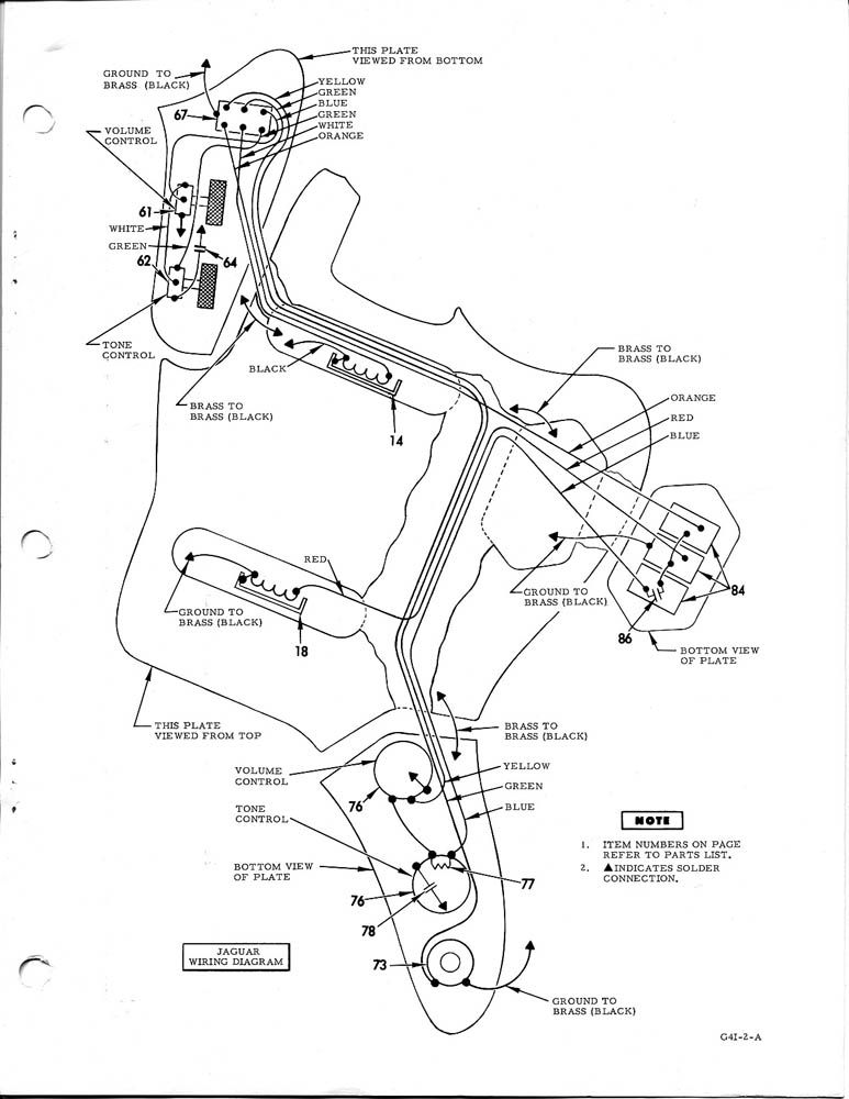 (The above schematic was "lifted" from a post by reTrEaD, back in August of 2012!) Here's your "list of mods" in two parts: a) Remove the wiring from the Bright switch (sometimes called the "strangle switch"). In doing so, you actually want to remove the capacitor entirely - you're going to run a wire directly from the middle terminal of the three switches down to the Vol pot. That's it for the first part. b) Now you want to move the Bridge wiring over to what was the Bright switch, and institute new wiring from your Mid pup to the switch that was controlling the Bridge. This new wiring will be a copy of the previous Bridge wiring. Be aware that you don't want to copy the Neck wiring, that's because of the Rhythm/Lead selection switch on the upper bout - a whole different kettle of fish! From these two mods, you now have a "Rhythm" section using the Neck Humbucker only, and a full complement section that has the ability to select pickups in any combination (albeit in parallel only). (Fender calls this the Lead section.) There is one thing that you didn't explain, so I'll be taking a WAG here.... that third pot, stationed where the output jack is supposed to be located - what's your intent there? (And I'll assume that the output jack has moved to the rim of the lower bout, something like a Telecaster.) Having that third control doesn't change anything about the actual pickup selection switching logic, just make the suggested modifications, and you're Golden! HTH sumgai |
|
|
|
Post by sumgai on Jul 16, 2023 22:20:08 GMT -5
frets , Wiring the tone controls is one thing, but when their effect should take place, that's what really counts here. You didn't say at which switch position should either tone control be in the circuit. Your short version of his wish-list seems to read "in Pos 2 (mid and bridge), he wants the upper control to have effect, and in Pos 1 (bridge only), he wants the lower control to be in charge". Is that about the size of it? You do realize that this implies that neither Tone control is in the circuit at any other time (positions 3, 4, or 5). Given the specs so far, a full SuperSwitch will be needed. Actually I see it as needing only 3 poles, but..... However, if the customer is willing to accept that the upper T-knob is always on when the Mid pup is selected (pos 2, 3 and 4), then we can do this with only a half-SuperSwitch. Further conversation with the customer should guide us down the path to fulfillment. EDIT: Given that I like the principle of "one position, one terminal", I now realize that where I said SuperSwitch above, a standard 3-terminal, 5-position shorting switch could also be used. Should keep the costs down. HTH sumgai
|
|
|
|
Post by sumgai on Jul 12, 2023 19:12:53 GMT -5
Giving an informed customer what they want is exactly the right thing to do Indeed! In my day, I had a mantra: "At the close of the business day, the money I got from an idiot customer is indistinguishable from the money I got from a reasonable customer." (Substitute "informed" as needed.) This concept made my life a lot less stressful, once I got it packed into my head for good and ever.  HTH sumgai |
|
|
|
Post by sumgai on Jun 25, 2023 15:58:09 GMT -5
Adding fuel to the fire:
Microsoft's new AI, named ORCA - a 10 minute introductory video:
Let the previous question be re-submitted, and new answers flow forth!
|
|
|
|
Post by sumgai on Jun 19, 2023 20:49:08 GMT -5
dayfud Please visit this article, it will tell you how to diagnose problems like yours, without having to take everything apart.. When you're done, report back to us with your results, and we'll see what's what. Brain Scanning For Strat-style GuitarsHTH sumgai
|
|
|
|
Post by sumgai on Jun 18, 2023 13:17:56 GMT -5
So, do you think it would make any difference if I moved the kill switch to the other side of the volume pot? Not normally what's done, but it certainly can't hurt to try it. Cheaper than just about anything else you can do, that's for sure. The Volume control, being a resistance, might be enough to "calm" the popping, though you'll want to monitor your tone for any differences. The last thing you can do is to swap out the switch itself. Test it for the condition mentioned by Yogi, is it a break-before-make, or the other way around. Many, but probably not most, switches made for momentary use (like yours) are make-before-break. To us, it sounds more like you have a break-before-make. That small amount of time that the contacts are completely open is likely enough to introduce that condition mentioned by Yogi, the collapse of the magnetic field causing a rather large (by comparison) jump in current. There's a science behind all this, but for your purposes, we needn't get into it until your problem is resolved. Then we can satisfy your curiosity. HTH sumgai |
|
|
|
Post by sumgai on Jun 16, 2023 20:21:21 GMT -5
Uh oh, somebody's brought an extra cap to the party. muddy, is there any difference in the pop (volume, tonality) when the cap is switched into the circuit versus when it's out of the circuit? sumgai |
|
|
|
Post by sumgai on Jun 14, 2023 23:59:25 GMT -5
The [not fully achieved] part is about that position #3; the phase switch has no effect there, though I want it to. I haven't figured out how, even with some special components in the guitar. I dunno, but the drawing(s) I'm looking at show S3 (the alleged phase switch) connected to the Middle pup. Kinda hard to figger out how that's gonna flip the phase of either the Neck or the Bridge pickup, when in Position 3..... Your Truth Table says that in. Pos' 2 and 4, you can use select either M(n) or M(s), and that seems to be the job that S3 is accomplishing, at the moment. While I can't read your mind, I'm able to offer some suggestions that might be useful, or maybe not.... 1) Leave off of selecting which coil of the Mid to engage, and move S3 to act as the desired phase switch on either of the other two pups. This leaves the Humbucker intact in the circuit, and hopefully that will be something you can live with. 2) If you must have a single coil operation in the Mid position, then replace that pickup as appropriate, and carry as in Choice 1. 3) Procure yet another switch, and place it on either the Neck or Bridge pup - leave everything else intact. (This can be a dead-stock push-pull on either of the remaining controls..) 4) Do away with the small filter cap on S3c, and use both that and (the currently unused) S3d to effect the phase reversal. At that point, your Truth Table becomes... truthful. From your point of view, this might make the most sense. EDIT: Oh hey.... Did you mean that Pos 3 should always be out of phase, and that a switch should not be necessary? Then simply swap one of the pickups leads, permanently. But in doing so, I have a feeling that this won't meet your expectations when in Pos. 2 (or 4) - that combo will also be out of phase. I ask this because your diagrams both denote in text, but don't actually show, S3 as selecting phase. In fact, I almost forgot to say something, but a studious look at the Truth Table reveals nothing about Pos 3 being out of phase, either by permanence or by selection. I'm sure you'll agree that that's the kind of detail that would be helpful to others, when reviewing your diagram(s). (Addtional reasoning: sometimes a casual viewer will "borrow" a diagram, and not bother to copy all of the surrounding explanatory text. It's nice to think that even if they never come back, at least they got something out of The NutzHouse that works.... or should work, if they know which end of the soldering iron to hold) EDIT (again): It should come as no surprise that the remaining (sixth) pole of the modified pickup selector won't make the grade - any time you swap pickup leads, you need two poles. At the least, I don't see any way to do it as currently wired up. Perhaps I'm wrong, and another member here can see a way to make it happen right on the 6P5T. We can only hope that such a person rises to meet the challenge.... EDIT (final for the night, I swear!): What would happen if you did this? S1a and S1b are jumpered on Pins 1 and 5 - remove them, they're redundant. All they were doing is grounding the common pin of S2c, but S1c wasn't passing any signal anyway, on Pos' 1 and 5. Now, if you were to remove S1c entirely, and hot wire across it, all 5 positions would have the fader, which is not desirable. Hence the remove of those jumpers - now you have the same effect as before. And S1c is now free to combine with S1f to make a polarity reversal switch for Pos 3 only. Try that, grasshopper, I think (negative emphasis on that last term) that this might work for you, but who knows, it's late at night and I'm no longer the smartest man in the room. (Not that I ever was, but I do like my delusions, you understand.  ) HTH sumgai |
|
|
|
Post by sumgai on Jun 7, 2023 12:47:00 GMT -5
arkham , That Seymour Duncan diagram looks good, it'll work for your purpose. Now, here's a diagram from our distant past, but it's exactly what you need to connect the pickups in parallel, series, or each one by itself:  Your assignment now is to put those two diagrams together, and post the results for us to review. Where Duncan shows a wire from the Mustang switch going to the LP-style pickup selector, that's where you want to substitute the 4-way Tele switch as shown above. The major difference will be, you cannot take the green/black wire from the Neck pickup straight to ground (as in Duncan's diagram) - it must go to the pickup selector as shown. If that's not done correctly, then you won't have a series connection, and other positions might also be "dead". HTH sumgai
|
|


 Like I said, double-check your work as you go. Another piece of advice might be to enlist a second pair of eyes. On occasion, it happens that one becomes convinced that something is correct when it's not - they're too familiar with the project. A second opinion often reveals the problem.


 to The NutzHouse!


 )
)