|
|
Post by ms on Mar 17, 2023 5:30:39 GMT -5
Think of the LCR meter as measuring the ratio of voltage to current at some frequency f, both amplitude and phase. If you have told it that it is measuring a capacitor, it assumes that you are right and then uses the values it measures to compute the capacitance and a loss factor. Same for inductance, and so on. So the capacitance measurement of a pickup must be made at a high enough frequency so that the inductance (in parallel) does not affect the measurement very much.
|
|
|
|
Post by ms on Mar 13, 2023 14:50:39 GMT -5
I think that falls off too slowly on the high frequency side to qualify as a resonance.
|
|
|
|
Post by ms on Mar 2, 2023 10:37:42 GMT -5
Have you compared the result with the more common method of putting a larger exciter between the two sets of poles?
You have shown in another current discussion that different screw heights can make a difference in frequency response when using a small exciter coil. It appears that a very conductive cover (brass), although it can nearly remove the resonant peak, does not cause a significant difference in frequency response between a KW type of coil, and the coil described in this discussion. In this comparison I use a "toothpick coil", that is, air core, but different from the one described above, using #41 wire for more turns per millimeter. First plot the difference between the amplitude in db of the response of the tc minus that of the kWc for an SD SH1 N with no cover. There is some difference age very high frequencies, where it does not matter. The difference at 5 KHz is about 0.06 db and less at lower frequencies. This is not significant. 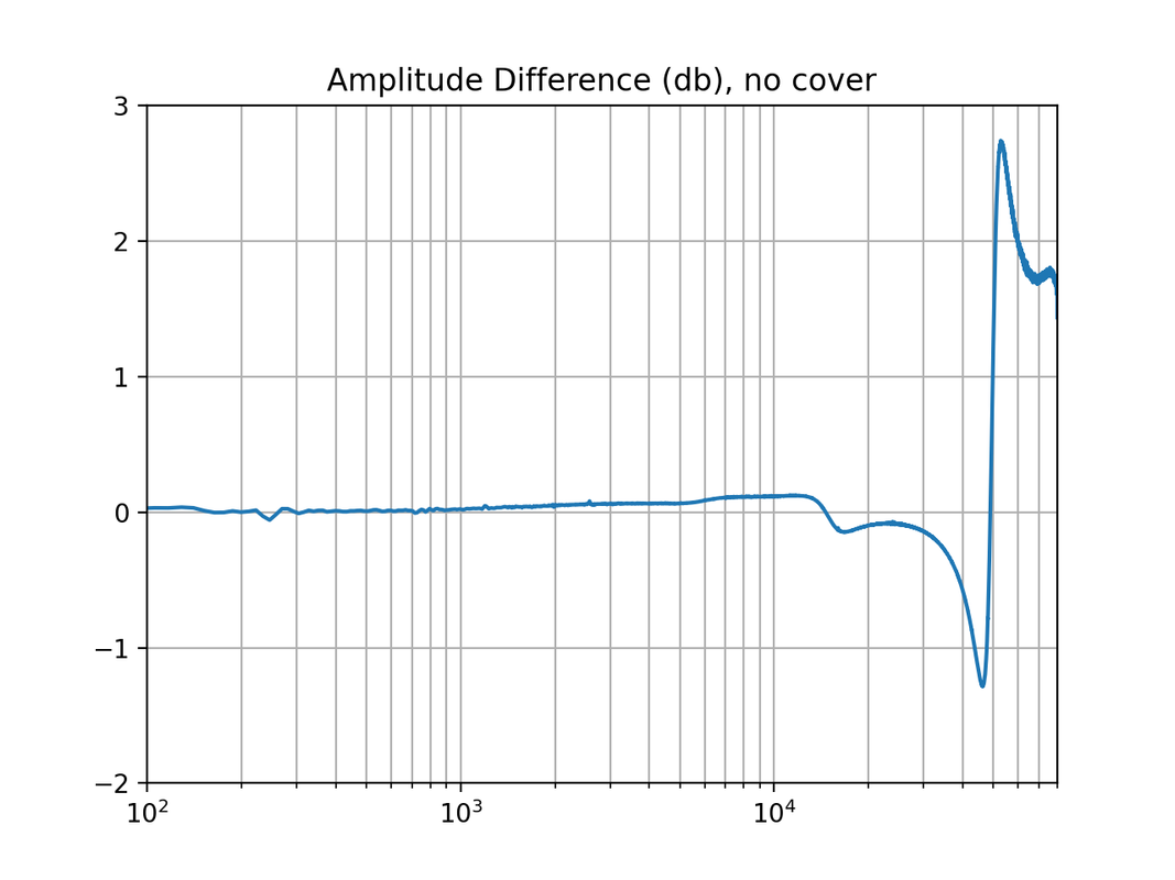 Then plot the same difference with a brass cover in place. The difference at 5 KHz increases to just under 0.5 db, still not significant. 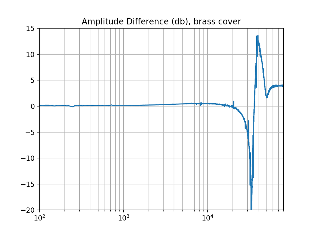 I will attempt aquin43's measurement with the SH1 instead of a mini humbucker. |
|
|
|
Post by ms on Mar 1, 2023 12:46:54 GMT -5
The pickup is a mini humbucker intended for jazz so it is not intended to exhibit a strong resonant peak. It has 12 adjustable poles and a metal case which gives it quite a high shielding loss. When properly balanced for loudness some of the pole screws are below the edge of the casing. Measured individually, these have more high frequency loss than the others. Another uncertainty is caused by it needing a large adjustment of the pole screws to balance it properly so it is probable that some of the signal from the string would come via the rails that carry the pole screws as well as via the screws
This is may be a special case but it does make an argument in favour of the tripole arrangement that you described in another thread.
Thank you, that is a great example of a case I have not looked at. The simplest explanation I can think of (certainly not necessarily correct) is that we have two fields inducing changing flux in the pole piece: 1. directly from the vibrating string; 2. from currents induced in the cover by the vibrating string. I would expect them to vary by different relative amounts as the height of the pole is varied; that is, a greater percent change in the field directly from the string because it is a small source further away. Source 2 increases in strength with respect to source 1 in frequency and therefore alters the frequency response of the sum. |
|
|
|
Post by ms on Feb 25, 2023 6:20:01 GMT -5
I have found at least one pickup that has a different frequency response at each pole when measure with a small coil.
I would be interested in seeing more about that. I have been using small coils for some time, believing that it should matter in some cases, but I have not proven that. Mike |
|
|
|
Post by ms on Feb 24, 2023 6:05:49 GMT -5
I have been comparing two very different exciter coils, and will post results soon. My conclusion is that there is very little difference in the measured frequency response even from coils that are very different. It does not seem to be necessary to illuminate the whole coil, or just one pole piece.
KW recommends 100 ohms in series with the coil, I believe. 30 or 38 AWG does not make a lot of difference to the total resistance.
With some coils you might not get the same current at high and low frequencies; it is important to so, or compensate somehow. I prefer to sample the current with a series resistor and then do cross spectral analysis so that the db and degrees at each frequency are independent of the amplitude and phase of the source.
An alternate approach would be to drive the coil with a very good active current source so that the amplitude and phase are very close to the same at all frequencies. I have not tried that.
|
|
|
|
Post by ms on Feb 19, 2023 11:51:10 GMT -5
A nice clear graph, and clearly what you are doing to relate open circuit to loaded parameters has worked realy well. Can you now also plot the Thevenin impedance vs frequency? (impedance ohms and phase) and would the phase related to that impedance be the same or different to the open-circuit phase plotted above? If its possible to output those parameters of open-circuit voltage, impedance and phase, then its a signature for that pickup that can be fed into any analysis of the circuitry downstream using classical theory. The process of making the loaded response from the the Thevinen equivalent uses the open circuit voltage, both amplitude and phase, and Thevinen impedance, both amplitude and phase. The plot in the first post shows both amplitude and phase of the open circuit voltage. The plot below shows the amplitude and phase of the impedance two ways. We need it with the effect of the C included, of course, and that is the blue and red lines. The lines with the C "unparalleled" are useful for showing that the L is more than just a simple L. One of the advantages of using a Thevinen representation for storing the information necessary to predict the response with any load is that we do not have to explicitly deal with the complexities of the inductor; we just need the measurements. 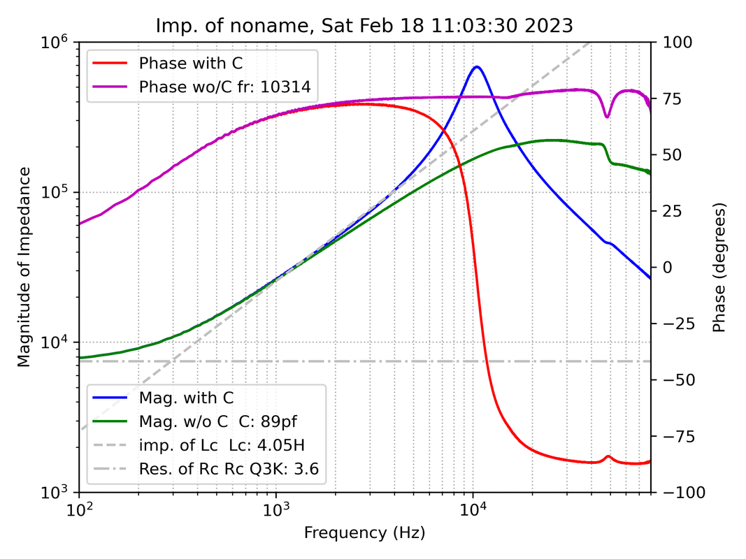
For further processing in Matlab and related applications, it would be convenient to store and retrieve the information in an hdf5 file. I was thinking that this would work for Excel as well, but as far as I can determine you cannot input into Excel from hdf5. It would be necessary to agree on some ASCII format. |
|
|
|
Post by ms on Feb 18, 2023 10:47:24 GMT -5
Compare calculated and measured loaded responses.
In the figure below the red is the measured amplitude of the response, and the magenta is the measured phase. The curves to the right of these are the computed open circuit responses. The curves to the left show the responses when loaded with 500 pf and 500 K ohms in parallel, shown two ways. The underneath solid color curves are the computation from the open circuit response, while the dashed curves are a measurement with that load. There is near perfect agreement. 
|
|
|
|
Post by ms on Feb 18, 2023 5:43:22 GMT -5
Why not? I have no commitment to the idea that you can, but what makes you say so? Measurements, modeling, and theory. |
|
|
|
Post by ms on Feb 17, 2023 19:25:17 GMT -5
And if you use the magnet core also as the bobbin, instead of an air core? You cannot get more than a few times no matter how high the permeability is. |
|
|
|
Post by ms on Feb 17, 2023 18:55:07 GMT -5
At the very least, I have confirmed that the equations do not work for Alnico, apparently because it is not linearly organized. That seems like it would line up with your explanation. I do not understand what you mean. |
|
|
|
Post by ms on Feb 17, 2023 18:53:59 GMT -5
According to your reluctance theory, what would you understand to change if we replaced the permanent magnet with a HyMu-core solenoid at equivalent field strength (relative permeability at this H is about 250,000)? I do not have a reluctance theory. I would prefer that reluctance and pickups were not ever mentioned in the same sentence or paragraph. I am not sure you could get the equivalent permanent magnetic field of an alnico magnet without saturating, but if you assume you can, then you would get about the same inductance and output as steel. The reason is that a short open core does not benefit from very high permeability. The huge "air space" limits the effect. No matter how high you make the permeability, you cannot get more than something like three times the inductance as with an air core. |
|
|
|
Post by ms on Feb 17, 2023 13:24:19 GMT -5
The field of a permanent magnet is not a function of the material's permeability. Permeability is a term relating to applied magnetic fields. Each region in a magnet makes a field and and is potentially influenced by the fields of all other regions, the same nasty "self-consistent" problem you often have. If the material is not permeable, such as almost holds true for neodymium, then there is no significant effect. Alnico is permeable, and so the effects of "applied magnetic fields" from region to region must be accounted for. |
|
|
|
Post by ms on Feb 16, 2023 13:52:00 GMT -5
The distances are given in mm, so I converted to Tesla and m then the result back to Gauss. If I set Br as 3000 I get exactly the table numbers. How are you handling mm if you use Gauss? All I did was check another source for Br of Alnico5. It gave the same number (12700 G) after converting from mT. That is why I think AK is right. Maybe both the other source and AK are wrong, but in any case, the field strength of strat pole pieces is well known, and there is no need to compute from Br. Edit: A couple more things: 1. The equation consists of Br times a unites factor. You have distance/distance, and so distance units do not matter, but all must be the same. 2. I believe this equation is for uniform magnetization. Alnico has sufficient permeability so that this is not completely correct, and you need a self-consistent solution. Exact agreement might be accidental. |
|
|
|
Post by ms on Feb 16, 2023 13:27:27 GMT -5
Again, no need for the attitude. I made no such assumptions. I took the measurement for Br and applied it to the formula for calculating field force at a distance from the center of the pole of a cylinder magnet: B(x) = {\frac {B\scriptstyle{ r }} 2} [ {\frac {L+X}{\sqrt{ R^2 + (L+X)^2}} } - { \frac x {\sqrt{ R^2 + x^2}} } ]
Seems I made a typo with X and x. Doesn't seem I can edit. This is all you wrote: ==>What do we know about average magnetization of strat pole pieces? This page suggests 12700, which seems very wrong; I think is right if the units are Gauss. |
|
|
|
Post by ms on Feb 16, 2023 11:46:05 GMT -5
==> This still does not explain why that would be true. I want to be able to explain this in terms of the theory.
The basic idea of a permeable material is that the atomic dipoles, or at least larger regions made up of such dipoles, have a tendency to line up with an applied field. But this is a self consistent problem: the field that affects a given region is the applied field and the field generated by the aligment of neighboring regions. This can happen much more easily in a direction through the material that is long rather than short (more regions to affect other regions). So magnetization is much stronger along the string than across it. The applied field from the pole along the string has opposite directions on opposite sides of the pole. Therefore the magnetization must be opposite on the two sides. Thus this longitudinal magnetization must pass through zero over the pole. Exact solution must be numerical, and measurements are not trivial.
|
|
|
|
Post by ms on Feb 16, 2023 11:31:42 GMT -5
Apparently you still have not realized the columns on the left of AK's table are properties of the material, not of specific magnets made from the material. Br (residual induction) is 12700 G for Alnico 5. What reason do you have for thinking it is too high? Well, none, you thought it was a measurement of a magnet, not a property of the material, only indirectly related to a measurement on a specific magnet. You want the math? Not going to work if you are unwilling even to look up the meaning of a column heading and try to understand how that fits into an understanding of a mathematical description of magnetic material properties.
|
|
|
|
Post by ms on Feb 16, 2023 6:10:13 GMT -5
That table on AK's web page suggests that you have about 1000 gauss 1 mm from the pole piece of a strat pickup. When I put the probe against the pole piece from some random strat pickup, I get just under 1000 Gauss on the end pole pieces and a couple hundred less on the others. Why are you wasting people's time with stupid questions like this when it is so easy to get a meter and see for yourself? If you do not understand the theory, a little hands on experience helps.
|
|
|
|
Post by ms on Feb 15, 2023 17:33:09 GMT -5
If we think that the magnet is only there to magnetize the string (and can be removed), why do we think that different magnet types matter? The permanent magnet can be moved to a different place, giving information about the string magnetization. I do not think anybody said it could be removed, as in taken away altogether. Magnets can be permeable and conductive, and thus contribute to the properties of the pickup electrical circuit as well. And of course in their role in magnetizing the string magnets of different strengths affect the vibration of the string in different ways. Do you now agree with our model of string magnetization? |
|
|
|
Post by ms on Feb 14, 2023 14:36:21 GMT -5
but the thing that makes the reluctance model appealing is that it automatically accounts for the contribution of the permeable core in the pickup, since you're looking at all the permeable elements at once, and how the sum reluctance between them changes when the guitar string is moving. I think that including the permeable core in the calculation of the reluctance difference is important and not easy. |
|
|
|
Post by ms on Feb 14, 2023 14:29:20 GMT -5
==> I think the answer is that Flux-max = Flux-saturation * Effective-area.
This equation does not imply that a small cross section means easy saturation.
==> How do you figure? It means exactly that.
On the left side we have flux; it must also be so on the right, and so Flux-saturation is a flux density, giving flux when multiplied by an area. So all this equation says is that the maximum flux through an area is found by multiplying the maximum flux density by the area.
==> Magnetic flux is famously difficult to shield, which is what "removing some of the flux" would amount to.
"Magnetic flux is famously difficult to shield" means that reducing the magnetic field to near zero is difficult. "Removing some of the flux" with high permeability material is easy.
Are there not more important things to discuss? For example, you are claiming that the model of consisting of longitudinal magnetization in the string which changes sign as it crosses the pole piece, producing a radial field, is wrong. Can you show some theoretical or experimental evidence for this?
|
|
|
|
Post by ms on Feb 14, 2023 10:18:48 GMT -5
|
|
|
|
Post by ms on Feb 14, 2023 10:09:27 GMT -5
==> I think the answer is that Flux-max = Flux-saturation * Effective-area.
This equation does not imply that a small cross section means easy saturation.
longitudinal magnetization:
I believe that aquin43 mentioned this above:
Remove the magnetization from the pole piece. Use a magnet* to magnetize from the side, that is, along the face of the pickup. The pickup works (good output) even though the permanent field does not point through the coil along the pole piece. Thus it works as we have described. If you do not want to remove a pickup magnet, you can reduce the output from one of the E strings by locating a magnet as described with the polarity selected to partially cancel the longitudinal magnetization caused by the pickup magnet.
* You need to use a magnet that could be used as a pole piece (such as an actual Fender type alnico pole piece magnet) in order to get the correct spatial field variation.
|
|
|
|
Post by ms on Feb 14, 2023 7:40:13 GMT -5
The magnetization of a long thin piece of permeable material is almost completely along it. In pickup, the component of permanent field along the pole axis does very little. The string is magnetized by the horizontal component (field bends over), which maximizes away from the center.
The component of time varying field in the direction through the coil results from the change in direction of the longitudinal magnetization.
|
|
|
|
Post by ms on Feb 14, 2023 6:04:58 GMT -5
So if the guitar string is always saturated, the reluctance model cannot explain things? The math above seems to suggest that with any normal pickup magnet, the strings are always saturated (as claimed by multiple articles). Also, if the permeable character of the string is changing, how could the change in flux consistently correspond to the velocity? As the string gets closer/further from the magnet, the rate of change of ɸ would increase/decrease, creating inconsistencies in the frequency produced from string velocity. That we demonstrably can achieve a consistent resolved frequency from a guitar string would seem to serve as evidence that this is not happening. The guitar string is not saturated right over the center of the pole piece and for some distance near the center. The direction of longitudinal magnetization changes as its magnitude passes through zero. The details and how they change as a function string position are complicated. Who said the induced voltage is exactly proportional to string velocity? It is actually significantly non-linear, (product of more than one factor) as aquin43 explained above. "Proportional to velocity" is just a good approximation. Antigua: The air gap between the string and the pole piece is a small part of the total air gap around the path of varying flux. The gap is so large that the main purpose of the variable reluctance method, simple solution for certain simple problems, does not apply. One of the conditions for a simple solution is that the air gap in the nearly complete path of permeable material must be small enough so that the fringing field (lines curving outward at the edges of the gap) is small. In the case of a pickup, the fringing field dominates, and other methods of solution are better. |
|
|
|
Post by ms on Feb 13, 2023 17:39:45 GMT -5
What is the source of the reluctance in question, then? It seems to me that the string remaining saturated is essential to the frequency creating a uniform signal, because once saturated dɸ depends only on string velocity (velocity of a constant flux). If ɸ is changing (not at saturation) then dɸ is flux-change-dependent velocity. In other words, if we can assume the string reaches saturation, we don't need to concern ourselves with the string's flux magnitude. Is the reluctance model stated formally somewhere? In the variable reluctance description, the reluctance around some path composed of permeable material changes when the position of a permeable object changes. For example, if we cut a slot in the cross section of a permeable toroid and move magnetic material in and out of the slot, the flux around the toroid changes, assuming, for example, a coil with current drives the flux, or maybe a permanent magnet. The magnetization in the moving magnetic material varies. If this moving magnetic material is saturated, then there still might be some change in the flux around the path, but this would be very subtle and I do not see how you could attribute to variable reluctance. |
|
|
|
Post by ms on Feb 13, 2023 7:37:05 GMT -5
This article seems quite good on the question of the magnetic component of guitar strings: www.gitec-forum-eng.de/wp-content/uploads/2020/08/poteg-3-string-magnetics.pdf. If I'm understanding the reluctance model, it is premised on the string reaching flux saturation such that it is no longer effectively permeable. The article suggests that due to tension-based construction requirements, very little variability is possible in steel grade and content. It also concludes that the saturation point for common strings is around 1.5T (15,000 Gauss). How could strings ever reach saturation if the strongest magnets in pickups are usually not even 1200 Gauss (.12T)? >> Edit I think the answer is that Flux-max = Flux-saturation * Effective-area. For High E that would mean .229mm diameter, which gives about 0.062µT (.0006 Gauss). So even with a high saturation point, the effective area is so tiny that it takes almost nothing to saturate.
The string saturates because it is made from a ferromagnetic material, and therefore has a permeability significantly higher than one. That is, the string in effect "amplifies" the field so that a relatively small applied field increases to a large value inside the string. The reluctance model does not depend on string saturation. As the reluctance varies, so does the magnetization of the string. This could result in the string going in and out of saturation, but the model works for weak fields with no saturation. |
|
|
|
Post by ms on Feb 8, 2023 6:52:22 GMT -5
I was hoping you would do a simulation. Thanks. Circuits using mutually coupled inductors, especially when more than one k is involved, are difficult to understand. The skin effect, creating variable frequency resistors, makes more complication. Here we have a circuit where an aspect of the response is simple. It ought to be good for something.
|
|
|
|
Post by ms on Feb 6, 2023 13:17:21 GMT -5
But it is not just that "it appears more inductive than it should be"; its inductive reactance at all frequencies is that of the low frequency inductance of the normal method (straight line on log log scale where the measurement is good). Here is the Fitler'tron with the new method:  and the original method: 
The inductive reactance at all frequencies is also that expected from the low frequency inductance of the normal measurement. The real part is even more reduced than that of the SDSH1N, approaching the low frequency value. |
|
|
|
Post by ms on Feb 6, 2023 7:19:53 GMT -5
I think that the reason for the disagreement with the other measurement method is a phase problem at higher frequencies. The calculation assumes that the induced voltage leads the current through the exciter by 90 degrees. The field seen by the coil, however, is the combination of the exciter field and the re-radiated field of the pickup losses. The phase of this combined field lags behind the assumed 90 degree lead so that when you calculate the impedance it appears more inductive than it should be. This phase error in the calculation rotates part of the resistive component into the inductive.
I think you are saying that there are differences in the eddy current losses between the two different methods of excitation. Maybe it works like this: when you excite by putting a voltage across the coil, eddy currents are induced in metal pieces by the B field made by the resulting current in the coil. When excite with a B field, eddy currents are also induced in the metal pieces directly by this field. I think that this has consequences for analyzing what the field from the vibrating string does. There are a couple of ways to proceed experimentally. First, increase the eddy current losses by using a cover. I have some brass covers on order, but it appears that they are coming from China; I did not realize this when I made the order. Also, I have a higher loss pickup (Filter'tron, or however that should be written) that I have started to measure. |
|


