|
|
Post by ms on Feb 5, 2023 12:25:00 GMT -5
Shown below is a measurement made with the alternate geometry shown in the lower panel from the previous post. The most striking difference between it and the "normal" measurement (shown further down) is that the imaginary part (the inductive reactance) does not bend over, but stays straight, up to the frequency where the measurement goes bad. Also the real (resistive) part is not as large. Why?   |
|
|
|
Post by ms on Feb 5, 2023 11:22:31 GMT -5
What I want is an independent method of measuring changes in frequency, that is, decreasing inductance and increasing resistance as a result of eddy currents. Results from the new method are not what I expected, but first let's look at how it works, and then the results later. The top panel of the figure below shows my normal method of measuring impedance. An ac voltage source drives the series combination of the pickup and a sense resistor (about 1K). Input 1 (to the recording interface) measures the voltage across this series combination, and input 2 measures the voltage across the sensing resistor, which gives the current. The ratio is the impedance through the series combination. A simplified model of a pickup is drawn inside the pickup box. In order to examine the details of L and R, it is necessary to "unparallel" the impedance of the C. This works fine, but it would be nice to have a method which removes the effect of the C in a different way. 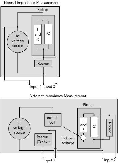
The bottom panel of the figure shows such a different method. An exciter coil is used to induce a voltage in the pickup coil. The voltage is induced around each turn, but of course using Thevenin's theorem, this becomes a single series voltage source. The exciter coil has an Rsense (165 ohms, value not critical, but needs to be known). The exciter coil is as described by Ken Wiltmont. Using the sense resistor is the easiest way to get accurate current information, both amplitude and phase. As usual, input 1 is used as a reference in a cross-spectral measurement with input 2. Rsense (input 2) is about 1K. This is small enough so that the input C of the recording interface and the C of the pickup have little effect. If we knew the value of that little voltage source, we would have a simple impedance measurement, similar to above. However, only the L and R would matter. Actually we only know the voltage to within a constant, and a 90 degree phase shift from the differentiation of the law of magnetic induction. The constant can be found by a calibration at low frequencies, where R can be measured by an ohm meter and the impedance of L is small. So that is a simple view of how it works; results later. |
|
|
|
Post by ms on Jan 6, 2023 9:44:15 GMT -5
Some thing appears to be wrong with what I have done, and so I have removed the explanation. I will work on it some more! OK, I had some connection issues with my equipment, and I was puzzled that my "Christmas present" recording interface has more than twice as much input C on insdtrtument channel 1 as on 2. (That is just the way it is since the switching on the two channels is different. So I am putting back this explanation. 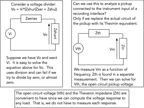 Also, here is an example of what you can do with both kinds of measurements used together:  |
|
|
|
Post by ms on Jan 4, 2023 18:42:52 GMT -5
Let's begin with the following plot: 
The red line is the voltage measured with an exciter coil with the pickup connected directly to the input of a recording interface with an input resistance of 1 M and a capacitance of 160 pf. The blue line is a computed approximation of the open circuit response. It requires as inputs the loaded measurement, the input impedance, and the pickup impedance. Notice that the peak frequency of the computed response is slightly higher than that of the measurement in the current discussion on string based exciter coils, which was made with a preamp with a lower capacitance than the interface (but not zero, of course). I will describe how the computation is accomplished in the next post, using Thevenin's theorem (https://en.wikipedia.org/wiki/Thévenin%27s_theorem), with the extension to ac circuits. This theorem says that a circuit composed of an arbitrary number of impedance elements, as well as voltage and current sources, can be replaced by an equivalent circuit with a single impedance in series with a single voltage source. The impedance is found by setting the voltages sources to zero, but leaving them in place as shorts, and removing the current sources. The impedance between the two terminals is then found. Thus, this impedance is the pickup impedance we measure. However, we do not have the open circuit voltage, but rather a voltage measured into a load, all be it a fairly high impedance, but not infinite. The problem then is to find the open circuit voltage (as a function of frequency) from the load voltage and the impedance. This is not hard, but is left for the next post. |
|
|
|
Post by ms on Jan 3, 2023 20:14:22 GMT -5
The toothpick coil has about 8 db less output than the string coil, still good. The tooth pick diameter is a bit more than twice that of the string. Not sure how that affects the field outside the solenoid.
|
|
|
|
Post by ms on Jan 3, 2023 10:37:49 GMT -5
This is a cool idea. Could it will model eddy currents in metal covers more effectively by having the magnetic lines intersect with the metal cover more like a real guitar string? Some portion of eddy currents are due to the cover, and some the pole pieces, maybe this configuration will place blame more accurately that an exciter that is focused more directly at the pole piece. Even if the string causes its own eddy currents, isn't that a realistic fact of what would happen with moving guitar strings? Maybe a toothpick could be used to avoid eddy currents if string eddy currents don't belong in the measurement, but guitar strings aren't made of wood. A big upside also seems to be that the pickup will magnetically couple with the steal string the way a real pickup would, and that might give a more true output measurement comparison between steel pole pieces versus AlNiCo, and other pole piece configurations, as compared to an air core exciter. Yes, that is what am thinking about a conductive cover like brass. Currents induced in the cover by the time varying field from the string reduce the pickup output. If the field is not right, the loss could be wrong. I do not know how big the effect is, but I think it cannot hurt to get it right, or at least close. The eddy currents in the string that I am concerned about result from the current in the coil around it. This is different from anything that might get induced by the string vibration. Your final point is subtle; I do not know if that makes a difference, but it is something to think about. |
|
|
|
Post by ms on Jan 2, 2023 17:29:09 GMT -5
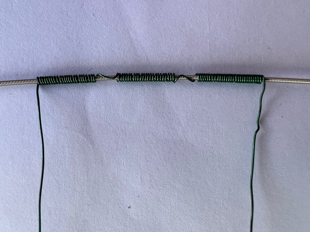
The purpose of the exciter coil described in this discussion is to make a magnetic field very similar in shape to that produced by the strong. This would, for example, excite a similar pattern of currents in the metal parts of a guitar pickup. When a guitar string is magnetized, it is like two long thin bar magnets along the string with like poles facing each other over the pickup pole piece. The vibrating string changes the flux from these magnets through the pickup coil. This driver coil uses a section of a string as a core magnetized by coils to simulate this field. Below is a photo of a coil setup for driving a pair of humbucker poles. The winding direction changes on opposite sides of a pole gap. The string has a dimeter of .042". The wrap is nickel, which has a permeability similar to carbon steel
 The coil is glued into a plastic (3D printed PLA) holder. 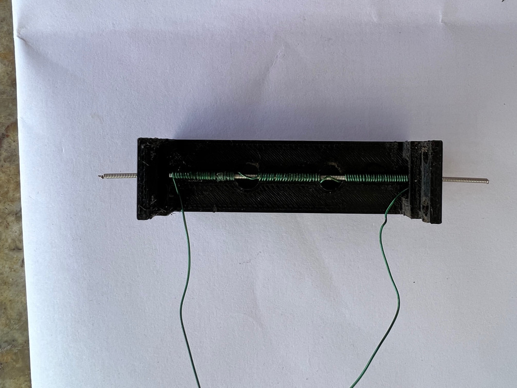 This is mounted over a humbucker located in a holder. 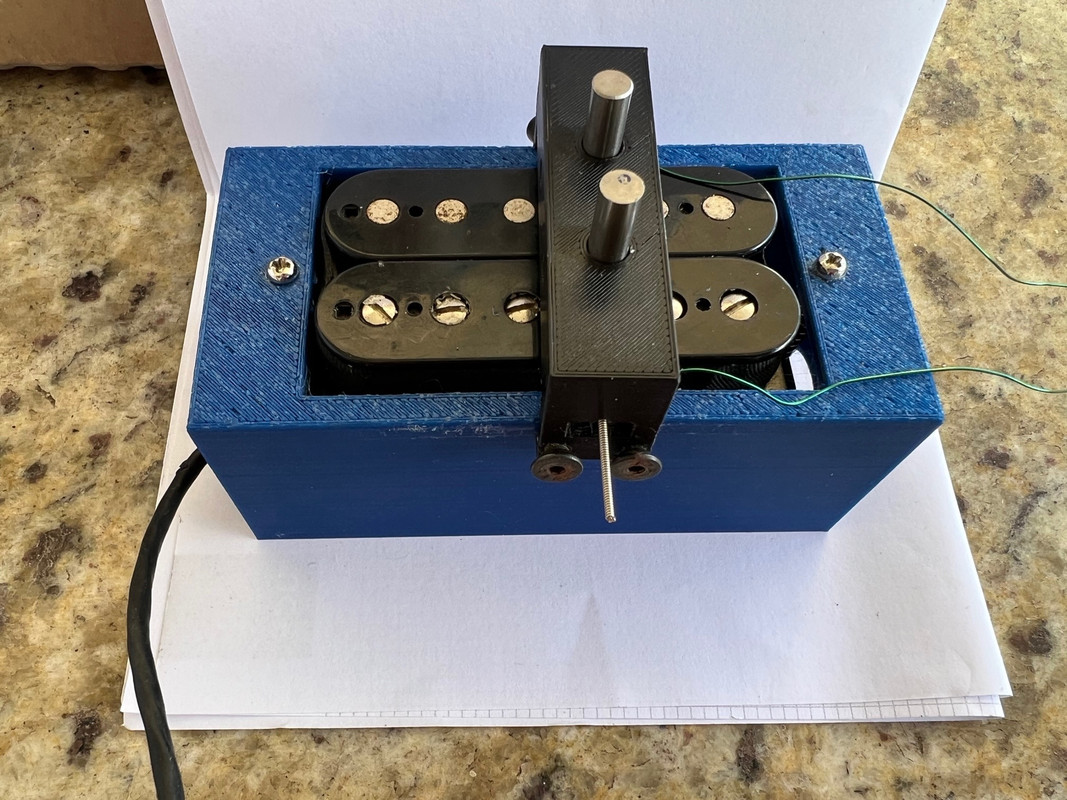 There are a couple of possible problems. First, there are eddy currents induced in the string core. Are they a problem? Second, Does the dc magnetization induced in the string by the pickup reduce the effectiveness of the excitation? For the second problem, the string can be demagnetized by a magnet(s) over the string. This makes some difference for a humbucker, but it is not really necessary since the string does not appear to be fully saturated by the pole pieces. This could be more important for a Fender type single coil pickup. However, even then there is a significant output since the saturation does not occur right over the pole piece since the magnetization goes through zero right over the pickup pole. The current through the exciter coil is from the headphone amp. About 0.1 amp gives a pickup output (SD SH1N) of about 100 mV at 1 KHz. The response of an SD SH1N is shown below. The red line is the response as slightly reduced at high frequencies by eddy currents. The green line is the corrected response. The correction factor is generated from a measurement made with a small low inductance coil, which has very flat response.  Below is this measurement. The exciter coil is down a bit more than 1 db at 10 KHz from eddy currents (assuming that there's not other effects). 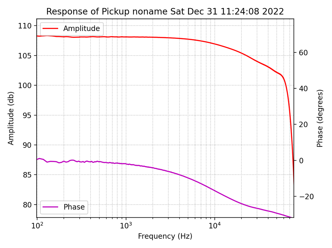 Below is a measurement of a 2.5 H strat type pickup. The higher Q is apparent.  |
|
|
|
Post by ms on Dec 25, 2022 7:03:24 GMT -5
I think the magnetic pull is mostly over the two pieces. The pole piece causes magnetization in the string that is like two thin rod magnets (along the string) with like poles facing each other. The field from the string magnetization pointing toward the pole piece is over it as aquin43 has shown, for example, in the model plot here: guitarnuts2.proboards.com/post/104632/thread. But still that's two points of attraction instead of one, so it would bend the string more broadly, like if you were to tug at the string with two fingers instead of one. Yes, and I like that comparison. Merry Christmas! |
|
|
|
Post by ms on Dec 24, 2022 6:30:38 GMT -5
The two coils also diffuse the magnetic pull over a wider area. The single pole AlNiCo 5 pole pieces pull on the strings in a specific spot, and it induces harmonics when the pickup is underneath the antinode of the harmonic, but since the magnetic field of this pickup isn't as sharply focused, it won't alter the harmonics exactly the same way, but probably still very similar. I think the magnetic pull is mostly over the two pieces. The pole piece causes magnetization in the string that is like two thin rod magnets (along the string) with like poles facing each other. The field from the string magnetization pointing toward the pole piece is over it as aquin43 has shown, for example, in the model plot here: guitarnuts2.proboards.com/post/104632/thread. |
|
|
|
Post by ms on Nov 25, 2022 13:46:06 GMT -5
If the pickup has inductance L and capacitance C, then each coil has inductance L/2 and capacitance 2*C. If you excite one coil, then the other forms a voltage divider with the instrument load. It is a parallel resonance that has a high impedance at roughly twice the pickup resonant frequency. This causes a steep fall off in this frequency range. Details could be more complicated, considering other impedances in the circuit.
As you show, low frequencies are not affected, and so you can get the low frequency gain by measuring the coils separately and adding the voltages. So you can compare the level of an SC and a humbucker.
|
|
|
|
Post by ms on Nov 16, 2022 13:05:22 GMT -5
I agree, but this will give you a comparison between a SC and one coil of an HB, when only one coil is excited (the other one is weakly excited, however). I think you would have to consider the excitation of both coils if it is an output comparison that you are doing, since the string does excite both coils of an HB.
I can't help but wonder, though, what is the purpose of comparing them? Is it, for example, making matched sets of HB/SC for some guitar? It is already common knowledge that HB are louder as far as I know. A really meaningful comparison depends on a reasonably accurate measurement. To make that work would require an exciter test arrangement that can be confirmed by comparison with actual string driven measurements. Also in this case, that would accommodate diverse pickup types. It's possible but not very easy. The problem is not to make it work, but to determine the measurement error confidently.
Measure one coil, and then the other. Add the voltages. To keep interactions down, I like small coils, a short cylinder with a diameter less than that of a pole piece. The coil is placed over a pole, of course. It is useful to measure relative low frequency output levels. Pickups with different frequency responses can be difficult to compare by listening. For example, if you have a resonance above 4 KHz, and lower it in steps by adding C, you might find that it gets louder sounding, presumably because the lower frequency resonance emphasizes harmonics that have higher output. |
|
|
|
Post by ms on Nov 16, 2022 10:44:04 GMT -5
Have you investigated exiting just one coil of a humbucker, or one coil at a time? Remember, the coils are in series, and so they should have very close to the same frequency response, but coupling between the coils could affect the results. How much? You could probably ignore the coupling at 100 Hz and get an output comparison between SC and HB at low frequencies. I think you get a funky result when you put the exciter over just one coil, because rather than get a combined output of the two coils, you get the output of one coil, loaded by the other, which end up being a different response than when both coils are producing voltages simultaneously. Consider the low frequency limit (about 100 Hz, say). The series circuit model consists of a single loop with a voltage source, the two coil resistances, and the load resistance. You measure the voltage across the load resistance. This is a very simple circuit. For example, you can rearrange the other three elements into a different order in the loop, and the measurement does not change. If you excite the coils one at a time and add the results, or excite them both at the same time (not changing the excitation amplitude) then you get the same answer. (That is, if you have two voltage sources in the loop you can add them to make a single voltage source.) |
|
|
|
Post by ms on Nov 16, 2022 5:53:35 GMT -5
Have you investigated exiting just one coil of a humbucker, or one coil at a time? Remember, the coils are in series, and so they should have very close to the same frequency response, but coupling between the coils could affect the results. How much? You could probably ignore the coupling at 100 Hz and get an output comparison between SC and HB at low frequencies.
|
|
|
|
Post by ms on Nov 15, 2022 10:19:27 GMT -5
|
|
|
|
Post by ms on Nov 6, 2022 10:43:17 GMT -5
That looks like a useful increase in measurement sensitivity.
Inside the meter is some value of the imaginary part of the measured impedance, that is, a reactance. The reactance of an inductor of 1.7H at 4KHz is about 42K; the reactance of a capacitor of 160pf at 4KHz is about -248K, small enough to make maybe a 20% error in the Q. As you said, this does not stop you from from choosing which cover material you have, but you need to remember that the Q measurement does have a significant error.
|
|
|
|
Post by ms on Oct 31, 2022 17:28:13 GMT -5
At 4 KHz the pickup capacitance can be a significant factor. This is one reason why the impedance measurement should be done by sampling and storing the data, followed by computer processing. (How else do you get out the effect of the capacitance at many frequencies?) That is, you need to process the raw impedance in ways that the meter cannot do. When used properly a good recording interface becomes part of an excellent piece test equipment system, one that you probably already own except for the software.
|
|
|
|
Post by ms on Oct 30, 2022 11:24:26 GMT -5
Same coil, 3 different cores at 1 KHz:
air: L = 1.460 Q = 1.67
Al5: L = 1.769 Q = 1.91
steel: L = 3.497 Q = 2.46
about as expected from your measurements. 1 KHz is kind of low to see large eddy current losses, but you have enough to determine the cover type. A more complete and interesting measurement would be to measure the impedance as a function of frequency (many frequencies), un-parallel the C, and then plot the Q as a function of frequency.
|
|
|
|
Post by ms on Sept 23, 2022 6:57:26 GMT -5
Putting a part of the exciter voltage in series with each of the model coils is a good idea. It has the physical justification that each turn of the pickup coil has a small voltage induced around it that can be simplified to a single voltage source for for as many turns as are simply connected in series. I am wondering if the the exciter voltage should be divided by fraction of total inductance as you do, or by the square root of inductance, which would be closer to the relative number of turns.
|
|
|
|
Post by ms on Sept 15, 2022 6:33:55 GMT -5
I could support the GITEC software by adding the specified hardware to the new integrator. As there was some discussion of different approaches, is there a way that the impedance measurement circuit could be jumper selectable between the GITEC and the circuit mentioned by member 'ms' on Aug. 22 above? I will have to review the circuits. In that case, what I have in mind is generally a panel with separate connectors for integrator and impedance measurement. What you describe in your last sentence is similar to what I have, but I do not use an integrator. A few years ago I used a very high impedance source follower, but I abandoned that. For my purposes, once you have the impedance, the additional information added by an exciter coil is not obscured by the input capacitance of the sampler, which can lower the resonant frequency significantly, but does not obscure the reduction of signal level by metal in the pickup in the frequency range of highest interest. Of course, not everyone would agree with me on this. I do not think it would be hard to make hardware that supports either of the two impedance set ups. You need different software as well; aquin43 has the additional required software for Octavia, I believe. I think that the combination of the hardware and software changes for implementing both methods would make this an unnecessarily complicated project. The method that I suggest makes better use of capabilities of the recording interface, and the software to achieve a simple but good impedance measurement is simpler than the GITEC software (which implements a frequency response correction, according to the documentation), also. |
|
|
|
Post by ms on Aug 22, 2022 7:09:20 GMT -5
The introduction to the write up of the pickup wizard sounds like a description of my device, but there are some important differences in the measurement geometry and thus the required passive network. The PW uses a large value resistor connected from the test signal to the pickup; the other end of the pickup goes to ground. The voltage across this resistor is used to measure current. Measuring this voltage requires differencing the voltages measured by the two channels of the recording interface. This tends to increase the relative size of errors. Also the high value of the resistor needed to keep the difference large at all frequencies means that full accuracy requires a correction.
I prefer a geometry using a small value resistor with one end connected to ground. (The measurement is that of the pickup plus the value of this resistor, which is accurately known and can be subtracted from the measured impedance) One channel of the RI measures this voltage. High frequencies are not an issue (2K versus 1M). Also, the measured impedance is proportional the ratio of the two measurements, further reducing high frequency errors, limited by differences in the high frequency responses of the two channels of the RI rather than the cutoff frequencies themselves.
Another difference is the PW sweeps a sine wave, but my device avoids sweeping by using a waveform containing all frequencies.
|
|
|
|
Post by ms on Aug 11, 2022 7:11:39 GMT -5
Reading the Zollner and Zwicker paper (linked above) on Q again, it seems that after they canvas all the complex issues around trying to arrive at a valid measure of Q (which I don't pretend to fully understand), they do hit on a pragmatic approach. And indeed one that they have used elsewhere (eg in the WRHB analysis series). That is, the simple 'peakedness' of the impedance frequency response curve - the peak height divided by an estimate of its width (from the two -3dB points). Their preference for that impedance curve (over the more common bode plot ?) seems based on their assessment that a simple OP amp circuit is 'easier' than an exciter setup; and perhaps also with it being a more 'hill-like' curve, with less ambiguous -3dB points (than an integrated or unintegrated bode plot ?). I think the more "hill-like" curve is the deciding factor in favor of the impedance curve. Even if you take out the 6 db per octave rise of the bode plot, you still are left with a low pass response, and there is no simple way to derive the Q accurately unless it is very high. The impedance curve is better; it is much less asymmetrical, falling to near zero on the high end and to the dc resistance on the low end. In other words, not perfect when the Q is low, but better. |
|
|
|
Post by ms on Aug 10, 2022 18:39:39 GMT -5
I haven't found a consistent one on the internet. Seems like that applies equally here. First pick a frequency at which to measure the Q. I choose 3 KHz because it is near the middle of the range of resonant frequencies achieved in practice The trouble with picking a fixed frequency is that you don't want to be too near the resonant frequency, with typical unloaded pickups that's quite unlikely but if 3kHz were very close to the resonant frequency you could (incorrectly) calculate a small, possibly even zero, Q from the method you describe. I forgot to mention that I compute the parallel C and then "unparallel" its impedance from the measured impedance. Then there is no problem with the resonance. Edit: A couple of examples of Q measured in this way (Q3K) are shown here: guitarnuts2.proboards.com/thread/9877/measuring-high-performance-strat-pickups |
|
|
|
Post by ms on Aug 10, 2022 10:29:14 GMT -5
Given the complexities as shown in Zollner's paper, here is reasonable method to measure the Q of a pickup for a relative guide to its sound.
First pick a frequency at which to measure the Q. I choose 3 KHz because it is near the middle of the range of resonant frequencies achieved in practice and near the maximum sensitivity of human hearing.
Next measure the complex impedance as a function of frequency, and look at the resulting curves to make sure that you have a good measurement. This uses the pickup alone, no loading, and the measurement device should not place a significant load across the pickup. The method Zollner shows is good. I prefer a method requiring no active electronics except the recording interface and computer.
Now compute 2*pi*f*L/R; this highlights the ratio of energy storage to energy dissipation. L is the the effective inductance at 3 KHz, derived from the imaginary part of the complex impedance at 3 KHz, L = 2*pi*f*Zi. It can be different from the low frequency inductance because of eddy current losses. R is the real part of Z at 3KHz, and it also includes eddy current losses.
The resulting Q can be as high as about 8 for very low loss ferrite cores and no metal parts in pickup. Of course it is much lower when there is lots of conductive metal in the pickup, especially steel cores and a thick high conductivity cover.
|
|
|
|
Post by ms on Jun 28, 2022 13:12:47 GMT -5
I think that the 1.2K input impedance of the mic. preamp means that the effect of the current noise flowing from its input is limited, and so I doubt that the source of the excess noise encountered with one of your pickups connected is its inductance.
|
|
|
|
Post by ms on Jun 27, 2022 13:13:17 GMT -5
Of course I have tried it  This was one of the first things I did to have some reference as I thought this will be a reference sound to compare. And... I was disappointed. There is much more noise when I connect XLR without transformer directly to the XLR microphone input. Moreover the sound is dull without higher range of high frequencies. It was strange to me, because I expected a full range pickup through XLR input. The same pickups connected to Hi-Z input of the amp through impedance matching transformer sound more full, with nice highs comparable with good passive magnetic pickup for acoustic guitars (my reference is Fishmann Neo-D pickup). Of course it does not sound as good as a guitar through a good microphone. I can hear that not all aliquotes (harmonics) are present comparing to pure acoustic sound. But I understand this is a beauty of magnetic pickup, which is not translating the acoustic sound of string, and even less of the whole guitar, but interprets string velocity changes with its own idiosyncrasies. It is my amp, that I use to test guitars as I test any guitar with pickup through the full range guitar amp using its "full range" speaker and to hear the real thing through the headphones. As customers have different amps, not all of them have mic input, and I wanted quite a universal solution I decided to concentrate on Hi-Z input. I thought that maybe the mic input is defective in my amp. I bought the amp used several years ago and used it with SM58 only several times and it works pretty well. I checked it today - still works with mic well, although the noise level is higher through this input, but I treat that as normal, because of extra gain. Nota bene, until now all the test are without any potentiometers or capacitors, pickup directly to cable with transformer on the other end then to amp. I still have to figure out how to do passive volume control. Krzyszt Is this noise "hiss", as when you have to turn the gain up high for a weak source, or is it something else? The dull sound might be the lack of equalization. For example, the tone stack in in a guitar amp is not flat when the controls are set to the middle, but has a distinct emphasis in the upper midrange extending into the highs. I do not know if the hi Z input you use for the acoustic guitar amp does as well, but if it is intended for a magnetic pickup it might. Also, a magnetic pickup (normal hi Z) itself has a resonance that can give a significant boost to the upper mid range and low highs. The resonant frequency of your low Z pickup would be too high to have this effect. |
|
|
|
Post by ms on Jun 27, 2022 10:06:39 GMT -5
Thank you for your answer. So it means, that if a guitar amp specs states a Hi-Z input of e.g. 2 MOhm, it is "seen" on the primary winds of 1:10 step up transformer as 20kOkm, yes? As this is more then 10 times bigger than output impedance of my pickup in any of acoustic frequencies, all is good, right? Both of my low impedance pickups designs under tests now have DCR below 300 Ohms as you have suggested (82 and 234 Ohms). The inductance at 100Hz is 0.07 and 0.19 H, but with transformer they both drives AER Alpha acoustic amp very nicely. I hear differences with different transformers and 2x288x0.14mm works better with Shure A85 and 2x432x0.1mm with Neutrik NTE 10/3, but it is subjective. Both transformers are stated to be 20 Hz - 20 kHz frequency range. Funny enough I made 2 coils on the same bobbins exactly as you have proposed with 1500 turns of 0.6mm wire, but they are not connected yet and they will be tested soon without transformer. I still do not understand how manufacturers chose and state one value of impedance, e.g. for dynamic microphones, when their actual impedance change dramatically with frequency. And low impedance pickups' output is similar to dynamic microphones. This is where my question came from. Krzysztof. The amp you mention appears to have a low impedance mic input; it probably does not have a transformer, but rather a low noise differential input amplifier. Have you tried your pickups into that with no transformer? This would give you a reference. If this is the amp the customer uses, you might consider not using a transformer. |
|
|
|
Post by ms on Jun 26, 2022 18:04:15 GMT -5
As a practical matter, if you have a transformer that is 300 ohms to 40 K and you connect the secondary to a 40K resistor you should measure about 300 ohms looking into the primary over the stated frequency operating range. If you lower the frequency, you should see the impedance drop and become inductive as a result of the primary inductance. Above the operating frequency range I would expect it to become capacitive as the importance of the leakage flux becomes more important.
You pickup is resistive at low frequencies. I would make it 300 ohms or less to avoid losing bass as a result of the transformer inductance. The load provided by the guitar amp is a lot higher than 40K, but this is not a problem. It means that as the impedance of your pickup rises with frequency (a result of its inductance) you should continue to get good performance. However, at some frequency below the stated operating range you should start to lose high frequencies since the effects of the transformer leakage inductance might matter at a lower frequency than normal because of the pickup inductance. But I think you do not really need to be good to 20 KHz, and it will be more than good enough.
My own preference would be to skip the transformer, and instead use maybe 1500 turns per coil rather than 5000, raising the resonance frequency (and losing some output level you do not really need in this application). Then I would find the value of resistor across the pickup to adjust the high frequencies to get the most natural sound.
|
|
|
|
Post by ms on Jun 24, 2022 13:35:29 GMT -5
I wonder, does an electric guitar, particularly a solid, really have a starting transient in the same way as some acoustic instruments, i.e. a short higher level inharmonic burst that initiates the sound? When you look at the output on an oscilloscope it seems just to start as it intends to go on. The waveform alters soon after the start but that is mostly dispersion in the string shifting the phases of the harmonics. There doesn't seem to be any huge starting peak to clip.
I agree; the second plot (pickup output, velocity) in the link above is consistent with the idea that when the pick pulls the string aside and is released, the string snaps back, sending along the string a transient that bounces back and forth. |
|
|
|
Post by ms on Jun 23, 2022 14:36:05 GMT -5
Soft ferrite (that is, with little if any permanent magnetism) is availalbe with many different permeabilities, including, as you said, some quite high. Very high permeability is only fully effective in a closed core, such as a toroid or other such shape as used in transformers. For the short open cores used in pickups, you can only get a few times improvement in performance no matter how high the permeability. Higher does not hurt, but it does not help much either. (Also yes, I would prefer solid rather than with holes.) So you might choose the type of ferrite based on something like "OK, this material has a permeability of at a least a few hundred, and, hey, it comes in the right size, and I can buy it now!"
I agree that you can get a very wide range of sounds with resistors and capacitors. This is one good reason for using a basic pickup design capable of high frequency and Q: it is not that hard to reduce either or both. Whether you want to have all that flexibility on one guitar, or use different guitars for different types of sound, is a matter of personal preference.
|
|
|
|
Post by ms on Jun 23, 2022 13:18:48 GMT -5
The definition of AWG is here: www.powerstream.com/Wire_Size.htm. Changing three wire sizes changes the resistance by a factor of 2. For one wire size it is the cube root of 2, that is, 1.2599.... Compounds that contain iron might or might not have high permeability, and thus might or might not potentially affect the inductance much. For example silicon (transformer) steel might have a relative permeability of 1500, while an AlNiCo (an iron alloy) magnet might have 4. Ferrite (ceramic) used for a permanent magnet is low, but ferrite with low permanent capability can be high. Also, the ceramic magnet in these humbuckers is not inside the core where it can affect the inductance significantly. So the ceramic magnet material should have almost no effect on the inductance, (but remember that the permanent field might change the permeability of the steel cores). No, I did not account for the change in length of wire when changing wire size. I am not convinced you can make this work out without accounting for the change in core permeability when the strength of the permanent magnet is changed, but that, of course, is just one factor among all these. |
|


